
Related Manuals for Bosch CE Series


Summary of Contents for Bosch CE Series
- Page 1 CE Series Heat Pump CE025 | CE035 | CE049 | CEO61 | CE071 Installation and Maintenance Manual...
-
Page 2: Table Of Contents
CE Series Heat Pump CONTENTS Troubleshooting.............. 25 Model Nomenclature............3 Electronic Thermostat Installation ........29 Initial Inspection..............4 Operating temperatures and Pressures......30 General Description............4 Wiring diagrams.............. 35 Moving and Storage............4 Notes ................39 Location................4 INSTALLATION ..............5 MOUNTING VERTICALLY..........5 MOUNTING HORIZONTALY..........5 HANGING BRACKET KIT..........6 CONDENSATE DRAIN ............7... -
Page 3: Model Nomenclature
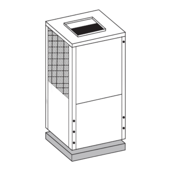
CE Series Heat Pump Model Nomenclature | 3 MODEL NOMENCLATURE Figure # 1 CE Series Heat Pump 6 720 220 048 (2014/08) -
Page 4: Initial Inspection
NOT use these units as a source of heating GENERAL DESCRIPTION or cooling during the construction process. CE Series Water-to-Air Heat Pumps provide the Doing so may affect the unit’s warranty. The best combination of performance and efficiency mechanical components and filters will available. -
Page 5: Moving And Storage
CE Series Heat Pump Moving and Storage | 5 INSTALLATION NOTE: 50° Minimum Entering Water MOUNTING VERTICALLY Temperature (EWT) for well water applications Vertical units up to six tons are available in left or with sufficient water flow to prevent freezing. -
Page 6: Hanging Bracket Kit
6 | Hanging Bracket Kit CE Series Heat Pump 2. Mount 5 Brackets to unit corner post using the bolts provided in the kit as shown on Figure#6. NOTE: IF unit is located in a crawl space, the bottom of the unit MUST be at least 4” above... -
Page 7: Condensate Drain
CE Series Heat Pump CONDENSATE DRAIN | 7 CONDENSATE DRAIN DUCT SYSTEM If equipped with float style condensate Supply air duct and return air duct flanges are overflow switch, final adjustment must be shipped unfolded with unit. made in the field. -
Page 8: Piping
8 | Piping CE Series Heat Pump The return air inlet to the heat pump must have at NOTE: Do not overtighten the connections. least one 90 degree turn away from the space return air grille. If air noise or excessive air flow are a problem, the... -
Page 9: Ecm Interface Board
CE Series Heat Pump Thermostat Connections | 9 THERMOSTAT CONNECTIONS Thermostat wiring is connected to the 10 pin screw type terminal block on the lower center portion of the ECM Interface Board. In addition to providing a connecting point for thermostat wiring,... - Page 10 1200 CFM. afterward. Refer to Figure #9 for factory programmed air delivery settings for the CE Series. WARNING: Remember to always turn To the right of the thermostat connection block is a green LED labeled dehumidify.
-
Page 11: Safety Devices And The Upm Controller
CE Series Heat Pump Safety Devices and the UPM Controller | 11 SAFETY DEVICES AND THE UPM • High pressure switch located in the refrigerant discharge line and wired across the HPC CONTROLLER terminals on the UPM • Low pressure switch located in the unit refrigerant suction line and wired across terminals LPC1 and LPC2 on the UPM. - Page 12 12 | Safety Devices and the UPM Controller CE Series Heat Pump If 24 VAC output is needed R must be wired to UPM DIP SWITCH DEFAULT POSITION ALR-COM terminal; 24 VAC will be available o the ALR-OUT terminal when the unit is in the lockout alarm condition.
- Page 13 CE Series Heat Pump Safety Devices and the UPM Controller | 13 • L.E.D. FAULT INDICATION: Two L.E.D. indicators are provided: Green: Power L.E.D. indicates 18-30 VAC present on board. Red: Fault indicator with the following blink codes; 1 - High Pressure Lockout...
-
Page 14: Upm Sequence Of Operation
14 | UPM Sequence of Operation CE Series Heat Pump UPM SEQUENCE OF OPERATION START RESET ON R RESET ON Y1 = ON R = 24VAC POWER/ SWITCHES/SENSOR CLEAR FAULTS STATUS CHECK BLINK CODE ON STATUS LED SOFT LOCKOUT COUNTER V >... -
Page 15: Electric Heater Package Option
CE Series Heat Pump Electric Heater Package Option | 15 ELECTRIC HEATER PACKAGE OPTION Each CE Series model has a number of heater sizes available. Refer to Figure #13 for heater package WARNING: The HP series heater compatibility with specific CE series units, model package requires its own electrical nomenclatures and electrical data. -
Page 16: Heat Recovery Package
16 | Heat Recovery Package CE Series Heat Pump HEAT RECOVERY PACKAGE 3. Close cold water inlet valve to water heater tank. The Heat Recovery Package (HRP) is a factory 4. Drain tank by opening drain valve on the mounted option. It consists of a forced pumped... -
Page 17: Water Tank Refill
Hot gas reheat is an active dehumidification option elements and thermostats, the lower element available on the CE series that cools and should be turned down to 100° F, while the dehumidifies return air, and then reheats it back to upper element should be adjusted to 120°... -
Page 18: Sequence Of Operation
18 | Sequence of Operation CE Series Heat Pump SEQUENCE OF OPERATION APPLICATION CONSIDERATIONS Cooling Mode Well Water Systems Energizing the “O” terminal energizes the unit reversing valve in the cooling mode. The fan motor NOTE: In well water applications a slow starts when the “G”... -
Page 19: Installation Of Pressure Regulating Valves
CE Series Heat Pump Installation of Pressure Regulating Valves | 19 Figure # 18 [1] Line voltage disconnect (unit) A refrigerant tap is provided in the refrigerant line located between the reversing valve and the water- [2] Flex duct Connection... - Page 20 20 | Cooling Tower/Boiler Systems CE Series Heat Pump When utilizing open cooling towers, chemical installed in the supply and return lines for unit water treatment is mandatory to ensure the water isolation and unit water flow balancing. Pressure/ is free from corrosive elements. A secondary heat...
-
Page 21: Geothermal (Earth-Coupled) Systems
CE Series Heat Pump Cooling Tower/Boiler Systems | 21 Geothermal (Earth-Coupled) Systems installation easy. Anti-freeze solutions are utilized when low evaporating conditions are expected to Closed loop and pond applications require occur. Refer to the GLP installation manuals for specialized design knowledge. No attempt at these more specific instructions. -
Page 22: System Checkout
22 | System Checkout CE Series Heat Pump SYSTEM CHECKOUT UNIT START-UP After completing the installation, and before 1. Set the thermostat to the highest setting. energizing the unit, the following system checks 2. Set the thermostat system switch to “COOL”, should be made: and the fan switch to the “AUTO”... - Page 23 CE Series Heat Pump Maintenance | 23 3. Lubrication of the blower motor is not required, however may be performed on some motors to extend motor life. Use SAE-20 non- detergent electric motor oil. 4. The condensate drain should be checked annually by cleaning and flushing to insure proper drainage.
-
Page 24: Unit Check-Out Sheet
24 | Unit Check-Out Sheet CE Series Heat Pump UNIT CHECK-OUT SHEET Customer Data Customer Name _____________________________________________ Date ___________________________________ Address ______________________________________________________ _______________________________________________________________ Phone _______________________________________________________ Unit Number ___________________________ Unit Nameplate Data Unit Make _________________________________________ Model Number ____________________________________ Serial Number ____________________________________ Refrigerant Charge (oz) __________________________... -
Page 25: Troubleshooting
CE Series Heat Pump troubleshooting | 25 TROUBLESHOOTING UPM Board LED Indications NOTE: Troubleshooting Information Indication Solution column may reflect a possible Color Blinks Description fault that may be one of, or a GREEN Solid 18-30 VAC Power is present combination of causes and solutions. - Page 26 26 | troubleshooting CE Series Heat Pump Unit Troubleshooting Problem Possible Cause Checks and Correction UNIT OFF ON Discharge In “COOLING” mode: Lack of or inadequate water flow. Entering water HIGH PRESSURE pressure too high temperature is too warm. Scaled or plugged condenser. In “HEATING”...
- Page 27 CE Series Heat Pump troubleshooting | 27 Compressor Ohms Model Start Winding Run Winding CE025 1.64 CE035 1.52 0.88 CE049 1.86 0.52 CE061 1.63 0.39 CE071 1.85 0.34 Tolerance +/- 7%. All resistance values must be measured with compressor at room temperature.
- Page 28 28 | troubleshooting CE Series Heat Pump Comfort Alert Module -Flash Codes Status LED Status LED Description Status LED Troubleshooting Information Solution YELLOW "ALERT” Open Start Circuit 1. Run capacitor has failed (may not be bad, verify) FLASH CODE 6 Current only in run 2.
-
Page 29: Electronic Thermostat Installation
CE Series Heat Pump Electronic Thermostat Installation | 29 ELECTRONIC THERMOSTAT INSTALLATION Position the thermostat subbase against the wall so that it is level and the thermostat wires protrude through the middle of the subbase. Mark the position of the subbase mounting holes and drill holes with a 3/16-inch bit. -
Page 30: Operating Temperatures And Pressures
30 | CE Series Heat Pump OPERATING TEMPERATURES AND PRESSURES Operating Temperatures and Pressures COOLING HEATING Entering Suction Discharge Water Suction Discharge Water Model Water Pressure Pressure Temp Temp Pressure Pressure Temp Temp Temp. F Flow PSIG PSIG Rise °F Drop °F... - Page 31 CE Series Heat Pump | 31 Operating Temperatures and Pressures COOLING HEATING 73-89 266-325 15-18 30° 77-94 272-333 16-19 117-143 189-231 14-17 18-22 86-105 279-341 17-21 40° 112-137 178-217 19-24 90-110 286-350 18-22 126-154 221-270 14-17 18-21 105-125 293-358 20-24 50°...
- Page 32 32 | CE Series Heat Pump Operating Temperatures and Pressures COOLING HEATING 64-78 248-303 15-18 30° 67-82 254-311 16-19 109-134 183-224 18-22 19-23 75-91 261-319 17-21 40° 105-128 172-210 10-12 20-25 79-96 267-327 18-23 118-144 214-261 18-22 19-23 78-90 273-334...
- Page 33 CE Series Heat Pump | 33 Operating Temperatures and Pressures COOLING HEATING 68-84 256-313 19-23 30° 73-89 261-319 20-25 113-138 172-210 18-22 19-23 81-99 277-339 22-26 40° 110-134 161-196 12-14 20-24 86-105 283-346 23-28 116-142 206-252 17-21 19-23 93-114 299-365 24-29 50°...
- Page 34 34 | CE Series Heat Pump Operating Temperatures and Pressures COOLING HEATING 71-87 259-316 19-23 30° 16.0 76-92 264-322 20-25 116-141 175-213 18-22 19-23 84-102 280-342 22-26 40° 16.0 113-137 164-199 12-14 20-24 89-108 286-349 23-28 119-145 209-255 17-21 19-23...
-
Page 35: Wiring Diagrams
CE Series Heat Pump Wiring diagrams | 35 WIRING DIAGRAMS Figure # 23 FOR REFERENCE ONLY Actual unit wiring may vary from this example. Always refer to the wiring diagram attached to the unit. CE Series Heat Pump 6 720 220 048 (2014/08) - Page 36 36 | Wiring diagrams CE Series Heat Pump Figure # 24 FOR REFERENCE ONLY Actual unit wiring may vary from this example. Always refer to the wiring diagram attached to the unit. 6 720 220 048 (2014/08) Subject to change without prior notice...
- Page 37 CE Series Heat Pump Wiring diagrams | 37 Figure # 25 FOR REFERENCE ONLY Actual unit wiring may vary from this example. Always refer to the wiring diagram attached to the unit. CE Series Heat Pump 6 720 220 048 (2014/08)
- Page 38 38 | Wiring diagrams CE Series Heat Pump Figure # 26 FOR REFERENCE ONLY Actual unit wiring may vary from this example. Always refer to the wiring diagram attached to the unit. 6 720 220 048 (2014/08) Subject to change without prior notice...
-
Page 39: Notes
CE Series Heat Pump Notes | 39 NOTES CE Series Heat Pump 6 720 220 048 (2014/08) - Page 40 40 | Notes CE Series Heat Pump 6 720 220 048 (2014/08) Subject to change without prior notice CE Series Heat Pump...
- Page 41 Bosch Thermotechnology Corp 555 NW 65th Court Ft. Lauderdale, FL 33309 Phone: 954-776-5471 | Fax: 954-776-5529 www.bosch-climate-us Revised: 08/2014...
Need help?
Do you have a question about the CE Series and is the answer not in the manual?
Questions and answers