Advertisement
Quick Links
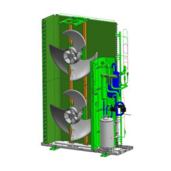
Service Instruction of BOSCH SPLIT ODU series
Issue Date
Summary
Provide Service Instruction of BOSCH SPLIT ODU for reducing vibration and noise.
Information
Applied model
- 1 Phase model : ODU Split 11s, ODU Split 13s, ODU Split 15s (Until September 2019)
- 3 Phase model : ODU Split 11t, ODU Split 13t, ODU Split 15t (Until September 2019)
* After September 1, 2019: Application of noise improvement pipe shape
- Noise improvement model When noise occurs,
it is possible to respond by attaching other than No. 3, 4 Dampers.
* Comparison of pipe shape before and after noise improvement
Old Pipe shape
(Until September 2019)
Service
Instruction
Rev1) 18. 02. 2020
Rev2) 25. 10. 2022
New Pipe shape
(After September 2019)
(1 of 25)
Advertisement

Related Manuals for Bosch SPLIT ODU Series


Summary of Contents for Bosch SPLIT ODU Series
- Page 1 Rev1) 18. 02. 2020 Rev2) 25. 10. 2022 Issue Date Summary Provide Service Instruction of BOSCH SPLIT ODU for reducing vibration and noise. Information Applied model - 1 Phase model : ODU Split 11s, ODU Split 13s, ODU Split 15s (Until September 2019)
- Page 2 (2 of 25) Service Guide Parts provided with service kit (for 3 Phase model) Description Spec Detail For prevent panel contact vibration Felt White felt(260x5x1 mm) (for external parts) For prevent panel contact vibration Insulation Black insulation,foam(500x10x3 mm) (for internal parts) Damper Ø...
- Page 3 (3 of 25) Service Guide Parts provided shown as image. 1. Felt 8EA 2. Insulation 5EA 3. Damper (Ø 19.05) 4EA 4. Damper (Ø 12.7) 2EA 5. Damper(Rubber) 1EA * 3EA for 3 Phase model 6. Damping sheet 1EA 7. Holder 2EA...
- Page 4 (4 of 25) Service Guide ■ Guideline to use service kit Step 1 : Attach the Insulation provided between ‘Side (left) panel’ and ‘Front panel’ refer to below instruction. (If necessary, Attach more insulation to other side) Step 2 : Attach the Damping sheet to back of ‘Front panel’ refer to below instruction. Step 3 : Insert the holders on top of the condenser.
- Page 5 (5 of 25) Service Guide ■ Detailed Instruction (Step 1) - Attach the Insulation to Attachment Surface of Side (left) panel shown below. - There are 3 Hook structures in Side (left) panel, So each of Insulation has to been attached between each Hook structure.
- Page 6 (6 of 25) Appendix Step 1 Hook Structure Hook Structure...
- Page 7 (7 of 25) Appendix Step 1 Hook Structure Hook Structure...
- Page 8 (8 of 25) Service Guide ■ Guideline to use service kit - Step 1 : Attach the Insulation provided between ‘Side (left) panel’ and ‘Front panel’ refer to below instruction. (If necessary, Attach more insulation to other side) - Step 2 : Attach the Damping sheet to back of ‘Front panel’ refer to below instruction.
- Page 9 (9 of 25) Appendix Step 2 Back of Front panel...
- Page 10 (10 of 25) Service Guide ■ Guideline to use service kit - Step 1 : Attach the Insulation provided between ‘Side (left) panel’ and ‘Front panel’ refer to below instruction. (If necessary, Attach more insulation to other side) Step 2 : Attach the Damping sheet to back of ‘Front panel’ refer to below instruction. - Step 3 : Insert the holders on top of the condenser.
- Page 11 (11 of 25) Appendix Step 3 Holder 2EA...
- Page 12 (12 of 25) Service Guide ■ Guideline to use service kit - Step 1 : Attach the Insulation provided between ‘Side (left) panel’ and ‘Front panel’ refer to below instruction. (If necessary, Attach more insulation to other side) Step 2 : Attach the Damping sheet to back of ‘Front panel’ refer to below instruction. Step 3 : Insert the holders on top of the condenser.
- Page 13 (13 of 25) Appendix Step 4 Front of Discharge Grille Back of Discharge Grille Back of Discharge Grille : White Felt (260 x 5 x 1 mm)
- Page 14 (14 of 25) Service Guide ■ Guideline to use service kit - Step 1 : Attach the Insulation provided between ‘Side (left) panel’ and ‘Front panel’ refer to below instruction. (If necessary, Attach more insulation to other side) Step 2 : Attach the Damping sheet to back of ‘Front panel’ refer to below instruction. Step 3 : Insert the holders on top of the condenser.
- Page 15 (15 of 25) Service Guide ■ Detailed Instruction (Step 5 For 3 Phase models) - The pipe schematic below shows the location of the damper attachment. - In the next page, damper structure added will be explained in four parts, such as whole part, Accumulator part, Comp_Discharge part, Comp_Suction part.
- Page 16 (16 of 25) Service Guide ■ Detailed Instruction (Step 5 For 3 Phase models) - There are 4 parts to show damper structure. Accumulator Part Whole part Pipe Schematic Comp_Suction Part Comp_Discharge Part...
- Page 17 (17 of 25) Service Guide ■ Detailed Instruction (Step 5 For 3 Phase models) - Add 5 dampers provided in direction shown below. (Whole part) - All dampers added for service have to be tied with a cable tie shown picture below. Pipe Schematic Damper (Ø...
- Page 18 (18 of 25) Service Guide ■ Detailed Instruction (Step 5 For 3 Phase models) - Add a damper (Ø19.05) provided in direction shown below. (Accumulator part) Damper (Ø 19.05) Accumulator Part (View from the right side) Pipe Schematic Damper (Ø 19.05) Accumulator Part Damper Structure for Service...
- Page 19 (19 of 25) Service Guide ■ Detailed Instruction (Step 5 For 3 Phase models) - Add 2 dampers (Ø12.7) provided in direction shown below. (Comp_Discharge part) Damper (Ø 12.7) Comp_Discharge Part (View from the left side) Pipe Schematic Damper (Ø 12.7) Comp_Discharge Part Damper Structure for Service...
- Page 20 (20 of 25) Service Guide ■ Detailed Instruction (Step 5 For 3 Phase models) - Add 2 dampers (Ø19.05) provided in direction shown below. (Comp_Suction part) Damper (Ø 19.05) Comp_Suction Part (View from the right side) Pipe Schematic Damper (Ø 19.05) Damper Structure for Service Comp_Suction Part...
- Page 21 (21 of 25) Service Guide ■ Detailed Instruction (Step 5 For 1 Phase models) - The only difference compared to instruction for 3 phase model is that you need to Add additionally Damper (Ø19.05) shown below. - The remaining of Damper structure for service is same with 3 phase models. Remove Damper (Ø...
- Page 22 (22 of 25) Appendix Step 5 Damper (Ø 12.7) Damper (Ø 19.05) Damper (Ø 19.05) Damper (Ø 19.05)
- Page 23 (23 of 25) Service Guide ■ Guideline to use service kit - Step 1 : Attach the Insulation provided between ‘Side (left) panel’ and ‘Front panel’ refer to below instruction. (If necessary, Attach more insulation to other side) Step 2 : Attach the Damping sheet to back of ‘Front panel’ refer to below instruction. Step 3 : Insert the holders on top of the condenser.
- Page 24 (24 of 25) Appendix Step 6 Attach Damper( Rubber) Attach Damper( Rubber)
-
Page 25: Installation Status
(25 of 25) Service Guide ■ Guideline to use service kit - Step 1 : Attach the Insulation provided between ‘Side (left) panel’ and ‘Front panel’ refer to below instruction. (If necessary, Attach more insulation to other side) Step 2 : Attach the Damping sheet to back of ‘Front panel’ refer to below instruction. Step 3 : Insert the holders on top of the condenser.
Need help?
Do you have a question about the SPLIT ODU Series and is the answer not in the manual?
Questions and answers