Table of Contents
Advertisement
Quick Links
Advertisement
Table of Contents

Subscribe to Our Youtube Channel
Related Manuals for Kyocera FS-7000+


Summary of Contents for Kyocera FS-7000+
- Page 2 Copying or other reproduction of all or part of this manual, any copyrightable subject matter without the prior written consent of Kyocera Corporation is prohibited. Any copies made of all or part of this manual, any copyrightable subject must contain the same copyright notice as the material from which the copying is done.
- Page 3 Introduction IBM PROGRAM LICENSE AGREEMENT ___________________________________________________________________ THE DEVICE YOU HAVE PURCHASED CONTAINS ONE OR MORE SOFTWARE PROGRAMS (“PROGRAMS”) WHICH BELONG TO INTERNATIONAL BUSINESS MACHINES CORPORATION (“IBM”). THIS DOCUMENT DEFINES THE TERMS AND CONDITIONS UNDER WHICH THE SOFTWARE IS BEING LICENSED TO YOU BY IBM. IF YOU DO NOT AGREE WITH THE TERMS AND CONDITIONS OF THIS LICENSE, THEN WITHIN 14 DAYS AFTER YOUR ACQUISITION OF THE DEVICE YOU MAY RETURN THE DEVICE FOR A FULL REFUND.
- Page 4 Introduction 3. Limitation of Remedies IBM’s entire liability under this license is the following; For any claim (including fundamental breach), in any form, related in any way to this license, IBM’s liability will be for actual damages only and will be limited to the greater of: the equivalent of U.S.
- Page 5 FONTWARE/TrueDoc developed by BITSTREAM INC. is provided as part of this Printer by KYOCERA CORPORATION under license. KYOCERA, as a Licensee of BITSTREAM, grants you, the Sublicensee, non-exclusive right to use FONTWARE/TrueDoc installed in this Printer, if you agree to and at all times comply with the following items:...
-
Page 6: Fcc Statement
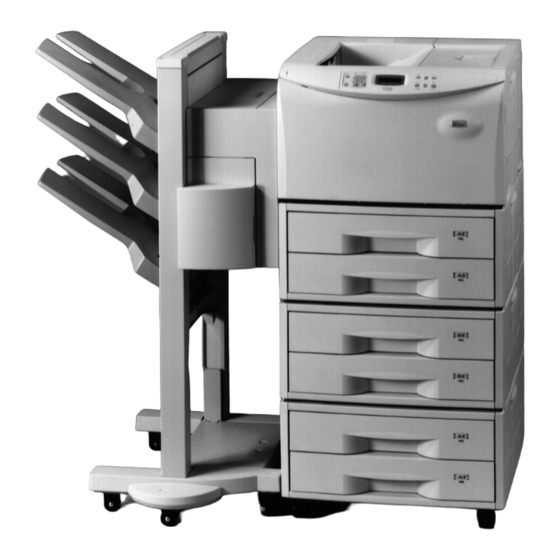
Caution to user Any modification without prior permission may cause harmful interference. If any modification/change is introduced to this equipment without prior permission, Kyocera as the manufacturer cannot guarantee compliance with FCC rules. To use equipment which does not comply with FCC rules is prohibited. - Page 7 Introduction The printer may be optionally installed with the following options: Conforming to the Class B limits PF-30 Paper Feeder (500 sheets) EF-1 Envelope Feeder UF-1 Universal Feeder DU-30/DU-31 Duplexers ST-30 Bulk Paper Stacker (3000 sheets) SO-30 Mail Box/Sorter DF-30/DF-31 Document Finishers (1800 sheets) HD-1/HD-2 Hard Disk Units BC-1 Barcode Reader...
-
Page 8: Interface Connectors
Introduction Interface connectors Important note on the interface connectors Be sure to turn off printer power before connecting or disconnecting an interface cable* to the printer. For protection against static discharge which may be applied to the printer’s internal electronics through the interface connector(s), keep any interface connector which is not in use capped using the protective cap supplied. - Page 9 Introduction CAUTION Laser radiation when open. DO NOT STARE INTO BEAM OR VIEW DIRECTLY WITH OPTICAL INSTRUMENTS. Use of controls or adjustments or performance of procedures other than those specified herein may result in hazardous radiation exposure. (U.S.A./Canada) (Europe/Asia) (Philippines) !"""...
-
Page 10: Important Safeguards
Introduction CDRH regulations The Center of Devices and Radiological Health (CDRH) of the U.S. Food and Drug Administration implemented regulations for laser products on August 2, 1976. These regulations apply to laser products manufactured after August 1, 1976. Compliance is mandatory for products marketed in the United States. - Page 11 Introduction This product is equipped with a 3-wire grounding type plug, a plug having a third (grounding) pin. This plug will only fit into a grounding-type power outlet. This is a safety feature. If you are unable to insert the plug into the outlet, contact your electrician to replace your obsolete outlet. Do not defeat the purpose of the grounding-type plug.
- Page 12 Introduction Declaration of Conformity (U.S.A.) Model Number: FS-7000+ Trade Name: Kyocera Responsible Party: Kyocera Electronics Inc. Address: 11465 John's Creek Parkway Suite #250 Duluth, GA30097, U.S.A. Telephone number: 770-623-2150 Fax number: 770-623-2151 Contact person for technical matter: Paul Bosak Phone:...
- Page 13 Introduction CE Marking Directive according to Council Directive 89/336/EEC and 73/23/EEC Manufacturer’s name: Kyocera Corporation, Printer Division Manufacturer’s address: 2-14-9 Tamagawadai, Setagaya Ward, Tokyo 158-8610, Japan declares that the product Product name: Page Printer Model number: FS-7000+ (as tested with enhancement optional units: PF-30, DU-31, DF-31, UF-1, BC-1, and HD-2) conforms to the following product specifications.
- Page 14 User’s instruction that conforms to the applicable specifications Technical drawings Descriptions of the procedures that guarantee the conformity Other technical information KYOCERA ELECTRONICS AUSTRALIA PTY., LTD Unit 6, 112 Talavera Road, North Ryde NSW 2113, Australia Phone: +61 2-9888-9999 Fax:...
- Page 15 Introduction Canadian Department of Communications compliance statement This Class B digital apparatus complies with Canadian ICES-003. Avis de conformité aux normes du ministère des Communications du Canada Cet appareil numérique de la classe B est conforme à la norme NMB-003 du Canada. ISO 7779 Maschinenlärminformationsverordnung 3.
-
Page 16: Moving The Printer
Keep it as level as possible, to avoid spilling toner inside the printer. If you ship the printer, remove the developer unit and ship it separately. Be sure to consult your Kyocera dealer before attempting long-distance transportation of the printer. - Page 17 Introduction ENERGY STAR As an ENERGY STAR Partner, Kyocera Corporation has determined that this product meets the ENERGY STAR guidelines for energy efficiency. The basic objective of the ENERGY STAR Program is to reduce environmental pollution by encouraging the manufacture and sale of equipment that uses energy more efficiently.
- Page 18 This product has been developed and manufactured with the express interest of reducing the impact on the environment. Using Kyocera's innovative cartridge free technology, Kyocera has created an advanced printing system that does not require the wasteful replacement and disposal of a cartridge.
-
Page 19: High Speed Printing
Introduction Introduction The Kyocera laser printer has many extremely desirable features. It was designed to make a contribution to a cleaner environment as well as to represent the latest generation of page printer technology. Superb print quality With an amorphous silicon drum, microfine ceramic toner, and the latest technology from Kyocera such as KIR (Kyocera Image Refinement) function*, this laser printer delivers superb print quality and clarity. - Page 20 HPLJ fonts. The scalable typefaces can be used at any size desired up to 999.75 points, in 0.25-point increments. KPDL (Kyocera Printer Description Language) The printer is equipped with KPDL (Kyocera’s implementation of the PostScript page description language) and Adobe PostScript Type 1 compatible 35 fonts.
- Page 21 The printer supports most Hewlett-Packard LaserJet 5M compatible symbol sets for both bitmap and scalable fonts. Display of printer messages in any of four languages English, French, German, or Italian. As an option it is also possible to download the messages in other languages. Please contact your Kyocera dealer.
- Page 22 Introduction Memory card slot for option fonts, macros, forms, etc. Data in the memory card can be selectively read from the printer’s control panel. Simple Network Management Protocol (SNMP) compliance Offers network managers complete open system network management. Large memory capacity This printer comes standard equipped with 8 MB of memory.
-
Page 23: Table Of Contents
Contents Contents Chapter 1 Installing the Page Printer..........1-1 Environmental Requirements of the Page Printer............1- 2 Unpacking and Inspection.................... 1- 7 When Not Using the Printer for Extended Periods............1- 9 Moving the Printer ......................1-10 Names of Parts ......................1-11 Setup and Connections.................... - Page 24 Introduction Chapter 3 Fonts................3-1 Bitmap and Scalable Fonts ..................3- 2 List of Fonts........................3- 3 Symbol Set ........................3- 8 Chapter 4 Maintenance ..............4-1 Toner Container Replacement ..................4- 2 Cleaning ........................4-10 Chapter 5 Troubleshooting............. 5-1 General Guide......................
-
Page 25: Chapter 1 Installing The Page Printer
Chapter 1 Installing the Page Printer Chapter 1 Installing the Page Printer This chapter uses illustrations to explain the names of parts of this printer, how to use it, its environmental requirements, and how to install it. Environmental Requirements of the Page Printer....1- 2 Unpacking and Inspection............ -
Page 26: Environmental Requirements Of The Page Printer
Environmental Requirements of the Page Printer Environmental Requirements of the Page Printer Places to Avoid Avoid installing the printer in locations subject to: Direct drafts of hot or cold air Direct drafts from outside (Avoid locations near doors leading outside.) Sudden temperature or humidity changes Sources of high temperature, for example, near stoves or radiators Excessive dust... - Page 27 Chapter 1 Installing the Page Printer Near an AC wall outlet, preferably one that can be used for the printer alone (see section Power Supply on next page.) Only use this printer under the voltage listed on the serial No. label attached to the rear panel of the printer.
-
Page 28: Power Supply
Environmental Requirements of the Page Printer Power Supply The printer should not be on the same power circuit as an air conditioner, fluorescent light, copier, or shredder, because these devices generate electrical noise on the power line. If it must share a power circuit with equipment like this, a high-frequency noise filter or isolation transformer is advisable. -
Page 29: Surrounding Space
Chapter 1 Installing the Page Printer Grounding Be sure to connect the ground wire for the printer's power supply to the ground terminal of the power outlet, to a copper pole buried at least 65 cm (25 inches) in the ground, or to a water pipe approved by the water department for use as a ground. - Page 30 Removing or changing parts other than disposable parts is prohibited. For repairs, contact the Kyocera dealer from which you purchased the printer. When moving the printer to a new location, contact the Kyocera dealer from which you purchased the printer.
-
Page 31: Unpacking And Inspection
Chapter 1 Installing the Page Printer Unpacking and Inspection Remove the printer from the package according to the steps given below. (See figure on next page.) After removing the printer, check that nothing is missing against the list of packaged contents. CAUTION Be sure that two or more people unpack and install the printer. - Page 32 Unpacking and Inspection Contents of Printer Box and How to Remove Them Power Cord Toner Kit (toner container, cleaning cloth) User’s manual and Kyocera Digital Library (CD-ROM) including the printer drivers and manuals. Remove the tape used for packaging as...
-
Page 33: When Not Using The Printer For Extended Periods
Also be sure to cover the printer so that dust does not accumulate. If the printer has not been used for two or more months, we recommend that you contact your Kyocera dealer to have it maintenanced. 1- 9... -
Page 34: Moving The Printer
Be sure to lift the printer gently, keeping it horizontal, to prevent toner from soiling the inside of the printer. When transporting the printer a long distance, contact the Kyocera dealer from which you purchased the printer. 1- 10... -
Page 35: Names Of Parts
Chapter 1 Installing the Page Printer Names of Parts Front View/Side View Face-Down Output Tray Power Switch Paper Full Sensor Vent Paper Stopper Control Panel Connector for Optional Feeder* MP (Multi-Purpose) Tray Side Cover Front Cover Paper Feeder Side Cover Upper Paper Feed Cassette Paper Feeder... - Page 36 Names of Parts Rear View Interior View Option Interface/Hard Disk Unit Slot Cover (OPT2) Memory Card Slot Toner Container Release Lever (Green) Parallel Interface Connector* ( Toner Top Cover Container Power Cord Connector Drum Unit Release Lever (Green) Option Unit (Service use only) Connector Lock Lever...
- Page 37 Chapter 1 Installing the Page Printer Setup and Connections Set up the printer according to the following steps. Install the printer on the paper feeder................Page 1-14 Open the top cover......................Page 1-15 Install the toner container....................Page 1-16 Close the top cover......................Page 1-19 Adjust the paper guide on the paper feed cassette.
-
Page 38: Setup And Connections
Setup and Connections Install the printer on the paper feeder. Align the installation holes on the bottom of the printer with the positioning pins on top of the paper feeder and slowly lower the printer into place. Check that the connector on top of the paper feeder is properly connected to the connector on the bottom of the printer. -
Page 39: Open The Top Cover
Chapter 1 Installing the Page Printer Open the top cover. Remove the packing tape stuck to the printer and gently lift the top cover as far as it will go. Top Cover 1- 15... -
Page 40: Install The Toner Container
Setup and Connections Install the toner container. Take the toner container from the toner kit. Shake the toner container with the protective seal facing up as shown in the figure five times or more to thoroughly mix the toner inside. Shake five or more times. - Page 41 Chapter 1 Installing the Page Printer Check that the two toner container release levers are positioned to the right (released) as shown in the figure. If not positioned to the right, slide them to the right until they stop. Toner Container Release Levers (positioned to right) Align the ends of the toner container with the grooves to the left and right inside the printer as shown in the figure and install.
- Page 42 Setup and Connections Check that the toner container is installed in the correct position, and push forcefully on the top of the toner container. After the toner container is installed, set the two toner container release levers to the left position (fixed).
-
Page 43: Close The Top Cover
Chapter 1 Installing the Page Printer Close the top cover. Close the top cover. Top Cover Adjust the paper guide on the paper feed cassette. The paper feed cassette attached to the paper feeder located at the bottom of the printer can be used to supply standard paper from A5 size up to ledger size by adjusting its paper guide and paper stopper position. - Page 44 Setup and Connections Paper feed cassette position Note: Be sure to remove the size Paper Guide indicator plates which are : Paper Size Indicator Position temporarily attached before using the printer. Paper Stopper Paper Guide Front Side Pull out the paper feed cassette until it stops. Open the paper feed roller located on the right side of the cassette until it stops as shown in the figure.
- Page 45 Chapter 1 Installing the Page Printer Paper Limit Indicator Paper Stopper Paper Feed Cassette Paper Guide Do not touch the rubber part of the paper feed unit. 1- 21...
-
Page 46: Add Paper
Setup and Connections Add paper. Try as much as possible to use fresh paper which has just been opened. Paper which has been stored long periods contains moisture and may result in sheets sticking together and/or paper jams. For specifications on the paper which can be used with this printer, please refer to Appendix B Paper Selection. - Page 47 Chapter 1 Installing the Page Printer Close the paper feed cassette. Paper is added to the second paper feed cassette in the same way. Size indicator plates are also supplied. Place these on the front of the cassette according to the paper size inside to make it easy to know the current paper size.
-
Page 48: Open The Paper Stopper On The Face-Down Tray (If Required)
Setup and Connections Open the paper stopper on the face-down tray (if required). Raise the paper stopper on the face-down tray. Paper Stopper Open the face-up output tray (when the tray is being used). Use the face-up output tray when you wish paper to be stacked with the printed side facing up (reverse order). -
Page 49: Connect The Printer To The Computer
Chapter 1 Installing the Page Printer Connect the printer to the computer. CAUTION Before performing this step, be sure to turn off the printer's power switch and unplug the power plug from the power outlet. Failure to do so may result in electric shock. A standard Centronics parallel interface connector ( ) and RS-232C/RS-422A serial interface connector (IOIOI) are located on the rear side of the printer. -
Page 50: Parallel Interface Connection
Setup and Connections Parallel Interface Connection Plug one end of the printer cable into the connector on the printer marked with a (parallel) symbol. Close the clips on both sides to fix the connector in place. Clips Printer Cable Plug the other end of the printer cable into the computer’s parallel (Centronics) interface connector. -
Page 51: 10. Attach The Power Cord
Chapter 1 Installing the Page Printer 10. Attach the power cord. CAUTION Be sure the printer's power switch is turned off. Note _____________________________________________________________________ Only use the power cord supplied with the printer. Plug the power cord into the power cord connector on the rear side of the printer. Power Cord Connector Power Cord Connect the other end of the power cord into a power outlet. -
Page 52: 11. Test The Printer
Setup and Connections 11. Test the printer. Use the following procedure to test the printer and print out a status page indicating factory settings. For details on the indicators and keys on the printer’s control panel, please refer to Chapter 2 Control Panel. -
Page 53: 12. Test The Interface With The Computer
Chapter 1 Installing the Page Printer 12. Test the interface with the computer. In order to check that the printer and the computer are properly connected you must print by sending an actual command from the computer. Turn on the printer's power switch and turn on the computer’s power as well. Wait until the message display switches from Self test to Ready. -
Page 54: 13. Install The Printer Driver
CD-ROM's root directory. Installing Under Windows 95/Windows 98 Insert the supplied CD-ROM (Kyocera Digital Library) into the CD-ROM drive of the computer. Click on “Start” with the mouse on the Windows95/98 Task Bar, and align the cursor with “Settings.” Click on “Printers” among the items displayed. - Page 55 Chapter 1 Installing the Page Printer The printer folder will open. Double click on “Add printer.” Windows 95 Windows 98 The Printer Wizard screen will appear. Click on “Next >.” A screen for selecting the printer to be connected will appear. Select the most appropriate printer and click on “Next.”...
- Page 56 Setup and Connections Select “Kyocera FS-7000+,” click on “Next >,” and follow the on-screen instructions to install. Once the driver has been properly installed, a Kyocera printer icon will be added to the printers folder. Note _____________________________________________________________________ When printing under Windows 95/98, be sure to set the emulation of this printer to HP LJ 5M/5Si (default setting).
- Page 57 Chapter 1 Installing the Page Printer Installing Under Windows 3.1 Insert the supplied CD-ROM (Kyocera Digital Library) into the CD-ROM drive of the computer. Double click on the “Control Panel”. Double click on “Printers.” 1- 33...
- Page 58 Setup and Connections Click on “Add >>.” A screen for “List of Printers:” will appear. From the choices, click on “Install Unlisted or Updated Printer.” 1- 34...
- Page 59 The install printer menu will appear. Enter “[CD-ROM Drive Name]: \” and click on “OK.” Select “Kyocera FS-7000+” from the printers displayed and click on “OK.” Once the driver has been installed, close the Control Panel by clicking on “Close.”...
-
Page 60: The Multi-Purpose Tray
The Multi-Purpose Tray The Multi-Purpose Tray The multi-purpose tray is incorporated on the right side of the printer. It can be used in one of two modes: first mode or cassette mode. The multi-purpose tray can hold about 100 sheets of paper (0.1 mm thickness). - Page 61 Chapter 1 Installing the Page Printer Feeding from the Multi-Purpose Tray Open the multi-purpose tray as shown in the figure. Multi-purpose tray Open the sub tray and adjust the paper guides according to the width of the paper to be fed. Paper guides Sub tray Note:...
- Page 62 The Multi-Purpose Tray Check that the message Ready is displayed in the printer's message display, and that the ON LINE indicator is lit. Set the paper source to the multi-purpose tray by pressing the FEED key until the message display indicates MP tray. The multi-purpose tray indicator on the control panel will flash, and Add paper will be displayed.
-
Page 63: Cassette Mode
Chapter 1 Installing the Page Printer Cassette Mode Press the MODE key to display Paper handling >. Press the (Form Feed) key to display >MP tray mode. After pressing the ENTER key, the mode display is changed by pressing the + and – keys. Display Cassette and then press the ENTER key. -
Page 64: Feeding Envelopes
The Multi-Purpose Tray Feeding Envelopes Envelopes should be fed face up. Be sure to set the print direction from the Mode Select Menu. Insert the envelopes in the tray as far as they will go. Do not load envelopes above the paper limit mark. Paper limit mark Envelopes For details on suitable envelope paper quality and shape, see Appendix B. -
Page 65: Expanding Memory
(SIMMs) in these slots. Note _____________________________________________________________________ The expansion memory should be installed only by a Kyocera authorized dealer or Kyocera certified technician. Kyocera shall not be liable for damage due to improper installation of the expansion memory. - Page 66 Expanding Memory The description given below is intended for service personnel. Precautions on the Handling of Extended SIMMs Static electricity which may accumulate in the human body through walking on carpets or other such surfaces is the enemy of SIMMs loaded with many semiconductor chips. Pay attention to the following things before installation to protect memory chips against damage from static electricity.
-
Page 67: Installing Simms
Chapter 1 Installing the Page Printer Installing SIMMs Insert the SIMM or SIMMs into the dedicated sockets on the printer's main board. WARNING Take precautions that no foreign substances such as metal chips or liquid get inside the printer during the installation process. Operation of the printer during the presence of a foreign substance may lead to fire or electric shock. - Page 68 Expanding Memory Turn off the printer's power and disconnect the power cord and all cables connected to the printer. Remove the six screws on the printer's rear cover, and remove the rear panel. There are two sockets for installing SIMMs located on the main board. Screws Sockets for Installing SIMMs...
- Page 69 Chapter 1 Installing the Page Printer Remove the SIMM or SIMMs from the package. Insert the connector end of the SIMM into the socket. Carefully push the board upright until it snaps into place. Make sure that the catches at the ends of the socket fit into the holes at the ends of the SIMM board.
- Page 70 Expanding Memory To remove a SIMM, carefully pull the end catches slightly outwards and tilt the SIMM as shown, then pull the SIMM out of the socket. After the SIMMs have been installed, reattach the rear cover on the printer and tighten all six screws securely.
- Page 71 Chapter 1 Installing the Page Printer Testing Extended Memory Check that the power switch is off, plug the power cord into the printer, and turn the power on. Wait for the printer's ON LINE indicator to light and the message display to read Ready, and press the STATUS key.
-
Page 72: Chapter 2 Operating The Page Printer
Chapter 2 Operating the Page Printer Chapter 2 Operating the Page Printer This chapter explains the printer's control panel and operating procedures. It also covers operations which use the memory card. Control panel..............2- 2 Operating Procedures............2- 11 Mode Selection Menu ............2- 24 Configuring Interfaces............ -
Page 73: Control Panel
Control Panel Control Panel The printer control panel consists of indicators, a message display, and various keys. Symbolic Indicators FORM FEED/ + key ON LINE Key CONTINUE/ ON LINE DATA ATTENTION CONTINUE FORM FEED RESOLUTION SIZE COPIES INTERFACE ENTER EXIT CANCEL STACK FEED... -
Page 74: Message Display
Chapter 2 Operating the Page Printer Message Display The message display displays the printer's operational mode. Messages which are displayed and their meaning are given in the table below. Message Meaning The printer is self-testing and warming up after power-up and is not ready to Self test print. -
Page 75: Interface Indicator
Control Panel Interface Indicator The interface indicator indicates the interface over which data is currently being received or was last received. When an optional interface such as a network interface is installed in the printer, this indicator displays the information in the table below depending on the interface used. Display Description Parallel interface... -
Page 76: Paper Size Indicator
Chapter 2 Operating the Page Printer Paper Size Indicator The paper size indicator indicates the paper size of the cassette currently installed in the printer (factory setting is A3) or the paper size currently set for the multi-purpose tray. During printing the paper size specified by the computer in data being sent to the printer will be displayed. -
Page 77: Copy Indicator
Control Panel Copy Indicator Indicates the number of copies set in the current interface (001 – 999), and the number is reduced as printing proceeds. Indicator Refer to the table below for the names and meanings of indicators on the control panel. Indicators on the Control Panel Indicator Name... - Page 78 Chapter 2 Operating the Page Printer Indicator Name Description Multi-purpose feed Flashing: Indicates that there is no paper in the tray or that indicator paper is jammed near the multi-purpose tray. Lit: Indicates when paper is fed from the multi-purpose feed tray.
- Page 79 Control Panel About the LED Indicator for the Paper Feed Cassettes The size indicator plate on the front of the paper feed cassettes is illuminated by LED. This LED indicates the status of the cassettes as follows depending on whether it is on, off or flashing. LED Status Meaning Flashing quickly...
-
Page 80: Control Keys
Chapter 2 Operating the Page Printer Control Keys DATA ATTENTION ON LINE CONTINUE FORM FEED INTERFACE RESOLUTION SIZE COPIES ENTER STACK FEED EXIT CANCEL STATUS MODE The functions of each key are given in the table below. Function ON LINE key Pauses and restarts printing. - Page 81 Control Panel Function CONTINUE/ (1) This key forcibly cancels errors and resume printing when printing is halted due to 3 key errors such as memory overflow. (2) This key functions as the 3 key during mode selection. It moves upward in the mode select menu and moves the cursor left.
-
Page 82: Operating Procedures
Chapter 2 Operating the Page Printer Operating Procedures This section explains basic operations of the printer and procedures leading up to and including printing. Operating Precautions Do not turn off power during printing. This may result in a paper jam or damage to the printer. Do not open covers on the printer or covers of optional equipment or open the paper feed cassette during printing. -
Page 83: Switching Power On
Operating Procedures Switching Power On Check that the power cord is securely plugged in at both ends. Check that the printer is connected to the computer (See page 1-28). Push the power switch to the ON ( | ) position. Power Switch Wait for the printer to warm up. -
Page 84: Basic Printing Operations
Chapter 2 Operating the Page Printer Basic Printing Operations The flow of basic operations to print is given below. Keys on the control panel are explained after that. For details on using the MODE key, be sure to read the section “Mode Select Menu” at the end of this manual in conjunction with this section. -
Page 85: Selecting The Output Tray
Operating Procedures Selecting the Output Tray Printed paper can be output on either the face-up output tray or the face-down output tray. Selecting the face-up output tray will cause paper to be stacked with the printed surface facing up. Selecting the face-down output tray will cause paper to be stacked with the printed surface facing down. -
Page 86: Feed Selection
Chapter 2 Operating the Page Printer Feed Selection Use the FEED key to select whether to feed paper from one of the paper feed cassettes or from the multi-purpose tray. If optional paper feeders (PF-30 or EF-1/UF-1) are installed, any of these can also be selected. - Page 87 Operating Procedures MP (multi-purpose) tray indicator Cassette indicator Switching Online/Offline After printing starts, it is possible to interrupt printing to check whether the print job is coming out as anticipated. Pressing the ON LINE key during data processing will cause the ON LINE indicator to go out and pressing it during printing will cause the printer to stop after the page currently being printed is finished.
-
Page 88: Canceling Printing
Chapter 2 Operating the Page Printer Canceling Printing Perform the following procedure when you wish to cancel printing after it has begun. Check if the message Processing is displayed in the message display. Press the ON LINE key to take the printer offline. Perform the necessary procedure on the computer to halt printing. - Page 89 Operating Procedures Press the CANCEL key again if you wish to stop the cancellation of printing. Press the ON LINE key to put the printer back online to continue with other print jobs. Notes ____________________________________________________________________ Canceling data from the computer using the CANCEL key will restore temporary settings to their default values.
-
Page 90: Status Printout
Chapter 2 Operating the Page Printer Status Printout It is possible to print out and check the printer's current status including unit emulation, font, printing range, and memory usage. Check that the ON LINE indicator lit and that the message Ready is displayed in the message display. - Page 91 Operating Procedures Sample Status Page 2-20...
- Page 92 Chapter 2 Operating the Page Printer 1 — Software version This information shows the software version and date of issue of the printer. 2 — Hardware information This information shows the currently selected paper feed source (indicated by an asterisk), paper size, paper type, and main settings of the printer.
- Page 93 Operating Procedures 8 — Fonts at startup (for each interface) This shows the font automatically selected when the printer starts up (default font). It is possible to set different fonts for the parallel interface and the serial interface. The figure on page 2-20 shows default settings.
-
Page 94: Form Feed
Chapter 2 Operating the Page Printer Form Feed Depending on the software, the message Waiting may be displayed in the message display when you get to the end of a print job. This occurs when the software does not issue a final form feed to the printer indicating the end of the print data. -
Page 95: Mode Selection Menu
Mode Selection Menu Mode Selection Menu This section explains the menu hierarchy used for all menus which can be set and selected using the MODE key. The MODE key can be used to display all of the menus in the table below. This mode selection menu conforms to the menu hierarchy given at the end of this manual. - Page 96 Chapter 2 Operating the Page Printer Menu Description Default Setting Set the number of copies to be printed. This can be set up to 999. Number of copies Switches the printer emulation. Emulation > HP LJ 5M/5Si The mode can be further set if KC-GL emulation is set. Selects the print font.
- Page 97 Mode Selection Menu Menu Description Default Setting Others > The following sub-menus can be displayed by pressing the 4 key and then the + or – key. Message language setting English Automatic form feed timeout setting 30 sec. Sleep timer setting [See page 2-56.] 30 min.
-
Page 98: Configuring Interfaces
Chapter 2 Operating the Page Printer Configuring Interfaces The printer is equipped with both a parallel and serial interface. Independent settings can be made for each interface. Optional interfaces can also be installed. To configure each interface, press the MODE key and use the + or – key to select the interface you wish to make settings for. -
Page 99: Emulation Selection
Emulation Selection Emulation Selection The following emulations can be selected for this printer. The emulation selected is stored even while the printer's power is off. Line printer IBM Proprinter Diablo 630 EPSON LQ-850 HP LJ 5M/5Si (Default setting) KPDL KC-GL KC-GL Emulation The following settings can be made from the sub-menu when KC-GL emulation is selected. -
Page 100: Reduction
Chapter 2 Operating the Page Printer Reduction (Page Set) Make settings on the page set menu to print at a reduced size. This menu is used to set the source paper size and the paper size to use after reduction. These settings can be made from within programs or files using the PRESCRIBE 2e SPSZ command. - Page 101 Reduction (Page Set) It is possible to set the following paper sizes (envelope) when using the PRESCRIBE 2e SPSZ command. The message display will show the messages given in the following table. Source Size-Target Size Combinations Source Size Indicator Target Size Indicator Reduction/Enlargement Ratio 100% CS 98%...
- Page 102 Chapter 2 Operating the Page Printer Source Size Indicator Target Size Indicator Reduction/Enlargement Ratio 100% 29.7 cm) A4 98% 100% (25.7 36.4 cm) B4 98% 100% (29.7 42 cm) A3 98% 2-31...
-
Page 103: Ram Disk
RAM DISK RAM DISK The RAM DISK function can be used when the total printer memory is 12 MB or more. A RAM DISK can be set up as a virtual media device by setting a given amount of the total printer memory as the RAM DISK. -
Page 104: Ram Disk Operations
Chapter 2 Operating the Page Printer Press the ENTER key again, and change the RAM DISK size using the + or – key. It is not possible to make a setting that exceeds total printer memory. The default value for the RAM DISK is the total printer memory minus 9 MB. -
Page 105: Virtual Mail Box (Vmb)
Virtual Mail Box (VMB) Virtual Mail Box (VMB) The Virtual Mail Box (VMB) function is a mail box function for the printer which does not require a physical mail box to be attached to the printer. The virtual mail box function can be used when RAM DISK mode is On or when an optional hard disk unit is installed on the printer. -
Page 106: Outputting To A Vmb
Chapter 2 Operating the Page Printer Outputting to a VMB When sending data to a virtual output tray set within the RAM DISK, make this setting from the printer driver. With this setting, data can be sent by specifying the desired virtual output tray number. It is also possible to assign a name to a virtual output tray and send data by specifying that name. -
Page 107: Print Accumulated Vmb Data With A Password
Virtual Mail Box (VMB) Display the VMB data you want to print. Pressing the ENTER key will cause Processing to be displayed and the data will be printed. Print Accumulated VMB Data with a Password This function prints VMB data protected by a password which has accumulated in a virtual output tray. Display >Print VMB data Tray. -
Page 108: Print Vmb Accumulated Data List
Chapter 2 Operating the Page Printer Press the ENTER key once the correct password is entered. Processing will be displayed and the data will be printed. If the password was incorrect, an error message will be displayed. (See page 5-11.) Pressing the CONTINUE key will return the printer to Ready status. Note that the password entered here is reset (returns to 00001) when this mode is exited. - Page 109 Virtual Mail Box (VMB) An actual VMB list printout will differ slightly from sample given above. Information regarding virtual output trays which are set will be displayed in the virtual mail box list. A mark is shown with the bin number for virtual output trays which contain data. If a password is set for a virtual output tray, there is no barcode shown for that virtual output tray.
-
Page 110: Operations For Using A Barcode Reader
Chapter 2 Operating the Page Printer Operations for Using a Barcode Reader If an optional barcode reader (BC-1) is connected to the printer, it is possible to print data within a virtual output tray using the barcode in the list. Select the barcode for "Output (1)" in the upper right using the barcode reader and then select the barcode for the virtual output tray you want to print. -
Page 111: Memory Card
Memory Card Memory Card This printer is equipped with a memory card slot. This allows, for example, the use of fonts other than internal fonts by using an optional font card. If a JEIDA Ver. 4.2/PCMCIA Ver. 2.1 memory card is used, it is possible to read, write and delete data and format the memory card. -
Page 112: Operating A Memory Card
Use a flash memory card or S-RAM memory card conforming to JEIDA Ver. 4.2/PCMCIA Ver. 2.1 which are approved by Kyocera. Be sure that its power is off when inserting or removing a memory card. Do not insert a memory card into the slot with undue force. -
Page 113: Reading Fonts From A Memory Card
Memory Card Note that only reading fonts and printing a list of partitions are possible when a font card is inserted. The following sections explain each of these operations. Each operation is described below. Reading Fonts from a Memory Card Fonts can be read into the printer's internal memory from an optional font card. -
Page 114: Reading Macros From A Memory Card
Chapter 2 Operating the Page Printer Reading Macros from a Memory Card Macro data on a memory card can be registered on the printer. Registered macro data can be used just like macro data located in printer memory. If a memory card already containing macro data is inserted in the printer, that macro data will be read into the printer automatically when the printer's power is turned on. - Page 115 Memory Card Notes ____________________________________________________________________ If the name of a macro on the memory card is the same as that in printer memory, the macro data on the memory card with the conflicting name will not be registered. Registered macro data will be lost if the memory card is pulled out. Re-execute >Read macro if this happens.
- Page 116 Chapter 2 Operating the Page Printer Writing Data (Partitions) to a Memory Card Data sent from the computer can be written on a memory card. Data written on the card can be read into printer memory by key operations from the control panel of the printer. Assuming the card has enough memory capacity, up to 127 partitions can be written on a single card.
- Page 117 Memory Card Check that the message display has changed to Waiting and press the FORM FEED key. The printer will automatically print the data just written (example below). This printout can be used to check the name (partition name) under which data was written and confirm that it was written properly.
-
Page 118: Deleting Data From A Memory Card
Chapter 2 Operating the Page Printer Deleting Data from a Memory Card It is possible to delete data names on a memory card one at a time. Check that the memory card can be written (that write-protection is released). Bring up the menu >Delete data on the message display. This display only appears if the memory card contains data. - Page 119 Memory Card Bring up the menu >Format on the message display. Press the ENTER key. ? will appear. Pressing the ENTER key again will cause Processing to appear in the message display and the memory card will be formatted. The printer will print memory card formatting information (example below) after initialization is finished.
- Page 120 Chapter 2 Operating the Page Printer Printing a List of Data Names (Partitions) This operation prints the contents (data names, data size, etc.) of the memory card inserted in the memory card slot. Bring up the menu >List of Partitions on the message display. Press the ENTER key.
- Page 121 Memory Card Note _____________________________________________________________________ "Remaining Size" in the partition list indicates the amount of remaining memory on the memory card. Since the system uses about 70 bytes to write a piece of data on the memory card, the actual available memory on the card is a little less than that displayed. 2-50...
-
Page 122: Setting The Paper Type
Chapter 2 Operating the Page Printer Setting the Paper Type This printer is capable of printing under the optimum setting for the type of paper being used. Setting the paper type for the paper source from the printer's control panel will cause the printer to automatically print in the mode best suited to that type of paper. -
Page 123: Making Settings
Setting the Paper Type Making Settings The following describes the procedure for setting the paper type using the Recycled type and Cassette 1 as examples. Display Paper handling > on the printer's Mode Select Menu and press the 4 key. Then use the + and keys to display the Cassette 1 type. -
Page 124: Paper Type User Setting
Chapter 2 Operating the Page Printer Paper type user setting The following describes the procedure used to set a user-defined paper type for the printer. Eight custom user settings may be registered. After having been set, any of these may be called up when setting the paper type for a paper source. - Page 125 Setting the Paper Type Press the 4 key after selecting the paper type you want to customize. Pressing the + or keys will cycle through a display of the submenus given in the table below. Submenus displayed Selection parameters Description >>Paper weight Light(Thin) Sets the paper thickness...
- Page 126 Chapter 2 Operating the Page Printer Pressing the ENTER key will cause the ? to disappear. Pressing the EXIT key will exit the setting. The same procedure can be used to set the parameters on other submenus. Note that the setting status for paper weight and fuser mode used for each paper type is as given in the table below.
-
Page 127: Sleep Timer Setting
Sleep Timer Setting Sleep Timer Setting This printer is equipped with a sleep timer function for conserving energy in cases where there has been no operation from the control panel or data has not been received for a predetermined period of time. -
Page 128: Dumping Received Data
Chapter 2 Operating the Page Printer Dumping Received Data It is possible to print data received by the printer as hexadecimal code for the purposes of debugging programs and files. Pressing the ENTER key once while >Print HEX-DUMP is shown on the message display will cause a ? to flash. -
Page 129: Kir Level
KIR Level KIR Level This printer incorporates the KIR (Kyocera Image Refinement) smoothing function. KIR provides high quality printing by providing a software-type improvement to the resolution. Print a status page to find out the current mode. The KIR setting is Off. - Page 130 Chapter 2 Operating the Page Printer Status page KIR Checking Lines KIR Setting Description Optimized stripes The current KIR setting is optimal. Dark vertical stripes The KIR mode currently set is too strong. Set the KIR mode to Off. (See the Mode Select Menu at the end of this manual.) White vertical stripes The KIR mode currently set is too weak.
-
Page 131: Ecoprint Mode
Ecoprint Mode Ecoprint Mode The Ecoprint enables you to reduce the amount of toner consumed on the page so as to save your printing costs. The factory-setting is off. Ecoprint is On Ecoprint is Off (default) Notes ____________________________________________________________________ Ecoprint status varies depending on the feed direction of the paper and the print direction. The Ecoprint setting has no effect on the print speed. -
Page 132: Resource Protection
Chapter 2 Operating the Page Printer Resource Protection When you switch from the HP LJ 5M/5Si emulation to another, all downloaded fonts and macros are lost. Resource protection preserves these PCL resources in memory so that they are intact when you change the emulation back to HP LJ 5M/5Si. -
Page 133: Adjusting The Print Density
Adjusting the Print Density Adjusting the Print Density If necessary, the print density can be adjusted from the Mode Select Menu. The required print density can be selected from five different steps (01 – 05). The factory setting is 03, and there is normally no need to alter this setting. - Page 134 Chapter 2 Operating the Page Printer Type of Error and Corresponding Audio Alarm (Buzzer) Priority Error Message Alarm Frequency Remarks High short beeps – Paper jam short beeps – Replace Toner Clean printer short beeps – Clean printer Press CONTINUE short beeps Option stacker path error...
- Page 135 Setting the Audio Warning (Buzzer) Priority Error Message Alarm Frequency Remarks short beeps – Print overrun Press CONTINUE short beeps – KPDL Error Press CONTINUE short beeps MEMORYCARD err## Press CONTINUE short beeps HARDDISK error## Press CONTINUE short beeps RAM DISK error Press CONTINUE short beeps Opt.
- Page 136 Chapter 2 Operating the Page Printer The alarm will continue to sound while the error condition continues (if the printer is in the sleep mode, the alarm will be silent for that period alone). The alarm will cease to sound, however, when the CANCEL key is pressed.
-
Page 137: Chapter 3 Fonts
Chapter 3 Fonts Chapter 3 Fonts This chapter describes the types of fonts you can use with the printer, including the printer’s resident and KPDL fonts, and symbol sets. Bitmap and Scalable Fonts ............3-2 List of Fonts ................3-3 Symbol Set................. -
Page 138: Bitmap And Scalable Fonts
Bitmap and Scalable Fonts Bitmap and Scalable Fonts A font is a set of characters of a particular design. The design is referred to as a typeface. Several characteristics identify a font. These include the font type (bit map or scalable), symbol set, spacing, pitch, height, style, stroke weight, and typeface family. -
Page 139: List Of Fonts
HP LaserJet fonts. KPDL Fonts The printer has 35 KPDL (Kyocera Page Description Language: Kyocera’s version of PostScript) fonts. The KPDL fonts are Adobe PostScript Type 1-compatible and have the suffix SWA at the end of... - Page 140 List of Fonts Resident Scalable Fonts (1)
- Page 141 Chapter 3 Fonts Resident Scalable Fonts (2)
- Page 142 List of Fonts KPDL Fonts (1)
- Page 143 Chapter 3 Fonts KPDL Fonts (2)
-
Page 144: Symbol Set
The page printer offers not only a large selection of bitmap and scalable fonts but also a large selection of symbol sets (also referred to as character sets). This is because the printers the Kyocera page printer emulates have a number of their own symbol sets for printing in different languages and other purposes. - Page 145 Chapter 3 Fonts Table 3.1. Bitmap Fonts Symbol sets SSET value SSET ID Symbol set ISO 60: Norway ISO 15: Italian ECMA-94 Latin 1 ISO 11: Swedish ISO 6: ASCII ISO 4: U.K. ISO 69: France ISO 21: Germany US Legal ISO 17: Spain HP Roman-8 PC-8...
- Page 146 Symbol Set Table 3.2. Scalable Fonts Symbol sets SSET value SSET ID Symbol set ISO-60 Norway ISO-15 Italian ECMA-94 Latin 1 ISO-11 Sweden ISO-6 ASCII ISO-4 U.K. ISO-69 France ISO-21 Germany US Legal ISO Latin 2 ISO-17 Spain PS math ISO Latin 5 Windows Latin 5 MS publishing...
- Page 147 Chapter 3 Fonts SSET value SSET ID Symbol set Windows PS text IBM PC-8 IBM PC-8 (D/N) Macintosh IBM PC-850 Pi font PC-852 Latin 2 Winbalt Windows Latin 1 PC-775 3-11...
-
Page 148: Chapter 4 Maintenance
Chapter 4 Maintenance Chapter 4 Maintenance This chapter explains how to maintenance the printer. This only covers replacing the toner container and cleaning parts such as the main charger unit and paper feed unit. Toner Container Replacement......... 4- 2 Cleaning ................4-10... -
Page 149: Toner Container Replacement
Toner Container Replacement Toner Container Replacement When there is not enough toner, the printer displays the message “ Toner low TK-30 ” in the message display. Be sure to prepare a new toner container when this message appears. If printing is continued in this condition, the printer will display the message “... -
Page 150: Replenishing Toner
Be sure to clean the inside of the printer along with replacing the toner container. For details, see Cleaning on page 4-10. Use of original Kyocera toner kits is highly recommended to prevent printer trouble and ensure the long life of the printer. - Page 151 Toner Container Replacement Slide the toner container release levers to the right until they stop and remove the old toner container. After removing it, take care not to tilt the toner container. Old Toner Container Toner Container Release Levers Cap the old toner container with the cap supplied in the new toner kit. Old Toner Container Push the cap securely in place.
- Page 152 Chapter 4 Maintenance Dispose of the old toner container in the plastic waste bag supplied in the new toner kit so that toner does not scatter. Plastic Waste Bag Old Toner Container Note _____________________________________________________________________ Although the toner container is made from non-harmful, flammable material, be sure to dispose of this waste according to local laws and regulations.
- Page 153 Toner Container Replacement Take the new toner container from the toner kit. Shake the toner container five times or more with the protective seal facing up as shown in the figure in order to thoroughly mix the toner inside. Shake five or more times Protective Seal Carefully remove the protective seal.
- Page 154 Chapter 4 Maintenance Check that the two toner container release levers are positioned to the right (released) as shown in the figure. If not positioned to the right, slide them to the right until they stop. Toner Container Release Levers (Positioned to the right) Align the ends of the toner container with the grooves to the left and right inside the printer as shown in the figure and install.
- Page 155 Toner Container Replacement Check that the toner container is installed in the correct position, and push forcefully on the top of the toner container as shown in the figure. 10. After the toner container is installed, slide the two toner container release levers to the left position (fixed) as shown in the figure.
- Page 156 Chapter 4 Maintenance 11. Close the top cover.
-
Page 157: Cleaning
Cleaning Cleaning Be sure to clean the main charger unit and paper feed unit along with replacing the toner kit. Also be sure to clean the inside of the printer periodically (about once per month) to ensure optimum print quality even if you are not replacing the toner kit. Note _____________________________________________________________________ If the toner container has been replaced when the message Replace Toner Clean printer was displayed, the message Clean printer Press CONTINUE will be... -
Page 158: Main Charger Unit
Chapter 4 Maintenance Main Charger Unit Cleaning the Charger Wire Clean according to the following procedure. Open the printer's front cover. Front Cover Pull the cleaning knob (green) located on the main charger unit slowly in and out a few times as shown in the figure. - Page 159 Cleaning Cleaning the Grid The main charger unit grid should be cleaned when the toner kit is changed. Take the grid cleaner from protective bag in the new toner kit, and remove the cap. Note _____________________________________________________________________ The grid cleaner pad is impregnated with water. Clean this part quickly to prevent the pad from drying out.
- Page 160 Chapter 4 Maintenance Attach the grid cleaner to the printer with the pad facing up as shown in the figure. Grid Cleaner After attaching the grid cleaner, slightly lift the main charger unit and repeat the action of slowly pulling the cleaning knob in and out at least five times. This will clean the grid inside the main charger unit.
- Page 161 Cleaning When the grid is clean, remove the grid cleaner from the printer and dispose of it. The grid cleaner is not re-usable. Close the front cover. This ends the charger unit cleaning procedure. 4-14...
-
Page 162: Paper Feed Unit
Chapter 4 Maintenance Paper Feed Unit CAUTION Wait a while after turning off the printer’s power to allow the fuser unit to cool (about 20 minutes). Do not touch the fuser unit as this may result in a burn injury. Fuser Unit Print problems such as soiling of the reverse side of printed pages may occur if the paper feed unit becomes dirty. - Page 163 Cleaning Turn the lock lever counterclockwise as shown in the figure to release the feed unit. Lock Lever Grasp the handle on the paper feed unit and slowly pull it out. Paper Feed Unit Handle 4-16...
- Page 164 Chapter 4 Maintenance Clean the saw-toothed seperator next to the transfer roller two or three times as shown in the diagram using the cleaning brush housed in the front panel of the paper feed unit. Return the cleaning brush after you have finished using it. Transfer Roller Cleaning Brush...
- Page 165 Cleaning 5. Wipe the paper dust on the registration roller and any dirt on the paper ramp using the cleaning cloth included in the toner kit. Cleaning Cloth Paper Ramp Registration Roller [Metal] Transfer Roller [Black] Paper Feed Unit Note _____________________________________________________________________ Be careful not to touch the transfer roller during cleaning as this may adversely affect print quality.
- Page 166 Chapter 4 Maintenance When you have finished cleaning the paper feed unit, push it back in until you feel it catch in place. Turn the lock lever clockwise as shown in the figure to securely lock the feed unit. Lock Lever 4-19...
- Page 167 Cleaning Close the printer's front cover. 4-20...
-
Page 168: Chapter 5 Troubleshooting
Chapter 5 Troubleshooting This chapter explains how to handle printer problems which may occur. If a problem cannot be corrected, please contact your Kyocera dealer. General Guide................5- 2 Print Quality Problems .............5- 4 Indicators and Messages............5- 8 Correcting a Paper Jam ............5-19... -
Page 169: General Guide
General Guide General Guide There are quite a few printer problems which may be corrected by the user. This section explains how to correct these problems. If some kind of printer problem should occur, check the following before concluding the printer is broken. - Page 170 Try printing another file or using another software. print command. If the problem occurs only with a specific file or application, check the printer settings for that application. If you still cannot correct a printer problem even after checking the above, please contact your Kyocera dealer.
-
Page 171: Print Quality Problems
There are many possible causes of the print quality problems, such as blank output, shown in the table below. The troubleshooting procedure for each type of problem is given below. If the checks explained in this section do not solve the problem, please contact your Kyocera dealer. Printed Results... - Page 172 Chapter 5 Troubleshooting Printed Results Corrective Action Dropouts, horizontal streaks, stray dots Clean the charger wire. Open the printer's front cover and clean the charger wire using the green cleaning knob. (See Chapter 4.) Black or white vertical streaks Check the message in the message display. If the Toner low TK-30 message is displayed and the toner indicator is flashing.
- Page 173 Print Quality Problems Printed Results Corrective Action The image is smeared. Clean the charger wire Open the printer's front cover and clean the charger wire using the green cleaning knob. (See Chapter 4.) Faint or blurred printing Check the Ecoprint setting. (See Chapter 2.) Try setting toner control to high density.
- Page 174 Chapter 5 Troubleshooting Printed Results Corrective Action Clean the main charger wire. Open the printer’s side cover. Pull the green main charger wire cleaning knob slowly in and out a few times. (See Chapter 4.) Check the main charger unit installation. Open the printer’s side cover.
-
Page 175: Indicators And Messages
Indicators and Messages Indicators and Messages This section explains the indicators on the control panel and the messages which appear in the message display and the appropriate corrective action to take in each case. Indicators Indicator Condition Corrective Action The printer has run low on toner. The toner should be replaced Flashing as soon as possible. -
Page 176: Maintenance Messages
Chapter 5 Troubleshooting Maintenance Messages Message Corrective Action Top cover The top cover is open. Open Close it tightly. Front cover The front cover is open. Open Close it tightly. Side cover The printer’s side cover is open. Open Close it tightly. Paper feeder 1 The paper feeder's side cover is open. - Page 177 Indicators and Messages Message Corrective Action Load (paper source) The paper size or type does not match the printing data. (paper size) (media type) One of MP tray, Cassette 1 to 6, or EF/UF (Envelope feeder/ Universal feeder) will be displayed In place of "paper source". Load the paper displayed on the message display and press the CONTINUE key to print.
- Page 178 Chapter 5 Troubleshooting Message Corrective Action Warning The printer’s internal memory is running low. Low memory Remove any unnecessary download fonts and/or macros. You can check the amount of user memory currently available by printing a status page. Toner low TK-30 There is not enough toner inside the toner container.
- Page 179 Indicators and Messages Message Corrective Action RAM DISK error ## 85: VMB: Alias error (Alias setting failure or no virtual bin corresponds to the Press CONTINUE alias.) Make the setting again. 86: VMB: Password error (No password specification, mistaken password, or password setting failure) Check the password.
- Page 180 The maintenance kit (MK-33) needs to be replaced. Replace the maintenance kit since the total number of printed pages has reached 350,000. Contact the licensed dealer of Kyocera from which you purchased the printer or service outlet. The maintenance kit includes a drum unit, developer unit and so on.
-
Page 181: Error Messages
Indicators and Messages Error Messages Message Corrective Action Memory overflow Current print processing cannot continue due to insufficient memory. Press CONTINUE Check available user memory by printing a status page, and either remove unnecessary download fonts and/or macros or expand the printer’s memory. Press the CONTINUE key to print data as far as it was stored. - Page 182 Chapter 5 Troubleshooting Message Corrective Action Insert the same Insert the same memory card. MEMORY CARD This message appears when the memory card has been removed from the memory card slot during memory card operations and replaced with a different memory card.
- Page 183 Indicators and Messages Message Corrective Action This message appears when an error occurs during access to the memory MEMORYCARD err ## Press CONTINUE card using the PRESCRIBE 2e RWER (ICCD) command or from the printer’s control panel. Look at the error code given in place of ## and refer to the corresponding description given below.
- Page 184 Chapter 5 Troubleshooting Message Corrective Action MEMORYCARD err ## 11: The memory card is full of data items. The number of data items which Press CONTINUE can be written on the memory card is limited to 127. Pressing the CANCEL key will restore the message Ready in the message display.
- Page 185 Indicators and Messages Message Corrective Action Processing Compressed data is printed due to insufficient memory. PAR FIT A4 Compressed data is printed due to insufficient memory when FIT flashes in the resolution indicator. The quality of printed data is reduced when this occurs.
-
Page 186: Correcting A Paper Jam
Chapter 5 Troubleshooting Correcting a Paper Jam This section describes how to remove paper when it jams in the printer. The printer will stop whenever paper jams in the printer or paper is not fed from a cassette. The printer will go offline and the message Paper jam Open front cover will appear in the message display. - Page 187 Correcting a Paper Jam Locating and Correcting Paper Jams Message Display Indicator and Paper Jam Location Indicator Meaning of Indicator Corresponding Printer Location Optional paper feeder (EF-1 or UF-1) Multi-purpose tray Paper feeder included with printer Optional paper feeder (PF-30) Optional paper feeder (PF-30) Optional paper stacker...
- Page 188 Chapter 5 Troubleshooting Correcting Paper Jams CAUTION Pull out the paper feed unit and wait a while to allow the fuser unit to cool. Do not touch the fuser unit as this may result in a burn injury. Fuser unit WARNING Take care not to leave any small pieces of paper in the printer when removing paper jams as this may result in fire.
- Page 189 Correcting a Paper Jam Indicator Meaning of Indicator Corresponding Printer Location Check the optional paper feeder When a paper jam occurs in the optional feeder, pull it out (EF-1 or UF-1). carefully. (For details, read the instruction manual for each (Only when installed) separate option.) Check the multi-purpose tray.
- Page 190 Suitable paper specifications are described in detail in Appendix B. If you have tried changing paper types and paper jams still occur frequently, there may be some problem with the printer. In this case, please contact your Kyocera dealer. 5-23...
- Page 191 Correcting a Paper Jam Paper Feeder’s Side Cover Figure 5.1 Paper jam in paper feeder unit Printer’s Side Cover (Left) Face-Up Tray Figure 5.2 Paper jam in face-up tray 5-24...
- Page 192 Chapter 5 Troubleshooting Registration Roller Open this cover first. Paper Feed Unit Figure 5.3. Paper jammed in paper feed unit Grasp the tab Fuser Unit Cover (green) to open. Raise this lever (green) when paper is hard to pull out. Tab (green) Figure 5.4.
-
Page 193: Chapter 6 Symbol Set Tables
Chapter 6 Symbol Set Tables Chapter 6 Symbol Set Tables The following tables show all the characters included in the most common symbol sets available with the five emulations. - Page 194 HP LaserJet 5M Symbol Sets HP LaserJet 5M Symbol Sets LaserJet 5M HP Roman-8 (8U) LaserJet 5M ECMA-94 Latin 1 (0N)
- Page 195 Chapter 6 Symbol Set tables LaserJet 5M US Legal (1U) LaserJet 5M IBM PC-8 (10U) To have the printer print the characters of decimal numbers of 7 through 15, and 27, set the printer to the HP PCL transparent mode (ESC&p#X).
- Page 196 HP LaserJet 5M Symbol Sets LaserJet 5M IBM PC-8 (D/N) (11U) LaserJet 5M IBM PC-850 (12U) To have the printer print the characters of decimal To have the printer print the characters of decimal numbers of 7 through 15, and 27, set the printer numbers of 7 through 15, and 27, set the printer to the to the HP PCL transparent mode (ESC&p#X).
- Page 197 Chapter 6 Symbol Set tables LaserJet 5M ISO Latin 6 (6N) LaserJet 5M PS Math (5M)
- Page 198 HP LaserJet 5M Symbol Sets LaserJet 5M PS Text (10J) LaserJet 5M Math8 (8M)
- Page 199 Chapter 6 Symbol Set tables LaserJet 5M Pi font (15U) LaserJet 5M MS publishing (6J)
- Page 200 HP LaserJet 5M Symbol Sets LaserJet 5M Windows (9U) LaserJet 5M Desktop (7J)
- Page 201 Chapter 6 Symbol Set tables LaserJet 5M ISO Latin 2 (2N) LaserJet 5M ISO Latin 5 (5N)
- Page 202 HP LaserJet 5M Symbol Sets LaserJet 5M WinBalt (19L) LaserJet 5M PC775 (26U) 6-10...
- Page 203 Chapter 6 Symbol Set tables LaserJet 5M PC-1004 (9J) LaserJet 5M Windows Latin 1 (19U) 6-11...
- Page 204 HP LaserJet 5M Symbol Sets LaserJet 5M Windows Latin 2 (9E) LaserJet 5M Windows Latin 5 (5T) 6-12...
- Page 205 Chapter 6 Symbol Set tables LaserJet 5M PC-852 Latin 2 (17U) LaserJet 5M PC-Turkish (9T) 6-13...
- Page 206 HP LaserJet 5M Symbol Sets Macintosh (12J) 6-14...
- Page 207 Chapter 6 Symbol Set tables LaserJet 5M International Characters 6-15...
-
Page 208: Appendix A Printer Specifications
Appendix A Printer Specifications Appendix A Printer Specifications... - Page 209 Printer Specifications Printer Specifications Item Description Printing method Electrophotography, Semiconductor laser + polygon mirror system Printing speed 28 pages/minute (landscape feed) (when printing multiple copies of 18 pages/minute the same page) 16 pages/minute Resolution 600 dots/inch (vertical and horizontal), includes KIR smoothing function (2400 dots/inch horizontal) First print (A4, 20°C) Sleep mode off - Approx.
- Page 210 Appendix A Printer Specifications Item Description Fuser Heat roller and pressure roller Toner saving Ecoprint mode Paper Plain paper (See Appendix B.) Paper sizes Cassettes: Ledger size, A3 to A5 universal cassette Multi-purpose tray: 80 mm x 148 mm to 297 mm x 450 mm Paper capacity Cassettes: 500 sheets each (80 g/m...
-
Page 211: Appendix B Paper Selection
Appendix B Paper Selection Appendix B Paper Selection... -
Page 212: Usable Paper
General Guidelines General Guidelines Although the page printer is designed for printing on standard dry PPC photocopier copy paper (standard paper), it can print on various types of paper that conforms to the specifications given in this chapter. Select paper carefully as use of paper inappropriate for the printer may result in paper jams or wrinkling of output paper. -
Page 213: Paper Specifications
Pulp content 80% or more Note _____________________________________________________________________ Consult with your Kyocera dealer before purchasing any specially treated paper or special application paper. Kyocera bears absolutely no responsibility for accidents resulting from the use of inappropriate paper which does not meet the specifications listed above. For paper, contact the licensed dealer of... - Page 214 Selecting the Right Paper Selecting the Right Paper The following sections explain the basic things to look for when selecting paper. Keep these things in mind when selecting paper. Condition of the Paper Avoid using paper that is folded at the corners, curled, dirty, stained, has a rough cut, fuzzy fibers, rough surface or is easily torn.
-
Page 215: Paper Size
Appendix B Paper Selection Paper Size Cassettes and the multi-purpose tray can handle the paper sizes listed in the following table. The printer automatically detects the paper size loaded in a cassette. Paper Sizes for Paper Feeding Paper Size ISO A3 420 mm ISO A4 297 mm... -
Page 216: Basis Weight
Selecting the Right Paper Basis Weight Basis weight is the weight of one square meter sheet of paper. Paper that is too light or too heavy can cause misfeeding, jams, and premature wear of the printer. Uneven paper weight can cause multiple feeds, print defects, poor toner fusing, blurring, and other print quality problems. - Page 217 Appendix B Paper Selection Store paper in a dry, well-ventilated location. Keep the paper flat and in its wrapping as long as possible. Rewrap paper that is not in use. Store paper in its original carton. Place a pallet etc. under the carton to separate it from the floor.
- Page 218 Selecting the Right Paper Packaging Select paper that is wrapped by the ream and then placed in a box. The best wrapping is one whose inner surface is coated to protect again humidity. Specially treated paper We recommend that you avoid using paper listed below which has been specially treated, even if it meets basic specifications.
- Page 219 Appendix B Paper Selection Special Paper This section explains printing on special paper. The page printer can use the following types of special paper. In this case, set the media type according to the table below. Paper type Media type Colored paper Color Preprinted paper...
-
Page 220: Colored Paper
Special Paper Specifications for each type of special paper are given below. Colored Paper Colored paper should meet the same specifications as listed for white bond paper in page B-3. In addition, the pigments used in the paper must be able to withstand the temperature of the printer’s fusing process (approximately 200°C [392°F]). - Page 221 Appendix B Paper Selection Thick Paper/Postcards Use postcards weighing 90 to 200 g/m . Any postcards of size 100 mm by 148 mm or larger may be used. Avoid using homemade postcards, picture postcards or postcards whose printing surface has been coated.
- Page 222 Special Paper Label The basic rule for printing on adhesive label is that the adhesive must never come into contact with any part of the printer. Adhesive paper sticking to the drum or rollers will damage the printer. Label paper must be manually fed. Label paper has a structure comprising three layers, as shown below.
- Page 223 Appendix B Paper Selection Table below lists the specifications for adhesive label paper. Adhesive Label Specifications Item Specification Weight of top sheet 44 to 74 g/m (12 to 20 lbs/ream) Composite weight 104 to 151 g/m (28 to 40 lbs/ream) Thickness of top sheet 0.086 to 0.107 mm (3.9 to 4.2 mils) Composite thickness...
-
Page 224: Appendix C Host Computer Interface
Appendix C Host Computer Interface Appendix C Host Computer Interface This appendix describes the signals used in the laser printer’s parallel, RS-232C/RS-422A interfaces. It also lists pin assignments, signal functions, timings, connector specifications, and voltage levels. The RS-232C/RS-422A protocols are also covered. -
Page 225: Parallel Interface Communication Modes
Parallel Interface Parallel Interface Parallel interface communication modes The printer features the fast data transmission on the parallel interface. The parallel interface mode can be activated from the printer’s control panel (see Chapter 2) as follows: Note _____________________________________________________________________ Use a parallel printer cable that complies with the IEEE1284 standards. Nibble (high) [default] High speed data communication is used in compliance with the IEEE 1284 standard. -
Page 226: Interface Signals
Appendix C Host Computer Interface Interface Signals The pins of the parallel interface connector carry the signals listed in Table C. 1. Asterisks in the table indicate signals that are active low. The table also indicates whether each signal is incoming or outgoing with respect to the printer. - Page 227 Parallel Interface In/out Description — Ground return — Ground return — Ground return — Ground return — Ground return Ignored [nInit] Error*, returns error status if FRPO O2=2 [nFault] — — — Not connected Power Ready Select In [NSelectIn] [ ]: Signal names in the Auto mode (IEEE 1284). In the Auto mode, these signals are bi-directional. Detailed descriptions of the signals follow.
- Page 228 Appendix C Host Computer Interface Paper Empty [PError] (Pin 12) This signal goes high when the printer runs out of paper. On-Line [Select] (Pin 13) This signal is high when the printer is on-line and low when the printer is off-line. It goes low when the upper unit is raised, or when the ON LINE key is pressed to set the printer off-line.
- Page 229 Parallel Interface Auxiliary output 1 (Pin 33) This signal line is not used. Power Ready (Pin 35) This signal is high when the printer’s power is on. Select In [NSelectIn] (Pin 36) This signal is used in some versions of the Centronics interface to enable the computer to force the printer on-line.
- Page 230 Appendix C Host Computer Interface Serial (RS-232C/RS-422A) Interface RS-232C interface Interface Signals The pins of the printer’s RS-232C interface connector carry the signals listed in Table C. 2. The table also indicates whether each signal is incoming or outgoing with respect to the printer. Table C.
- Page 231 Serial (RS-232C/RS-422A) Interface RXD – Receive Data – (Pin 3) This input carries serial asynchronous data sent by the computer to the printer. RTS – Request To Send – (Pin 4) This output is always held high (above 3 volts). CTS –...
- Page 232 (or similar device) equipped with an RS-422A serial interface. Note _____________________________________________________________________ The changing of the main circuit board jumper connector should be carried out only by a Kyocera authorized dealer or Kyocera certified technician. Kyocera shall not be liable for damage due to improper changing of this main circuit board jumper connector.
- Page 233 Serial (RS-232C/RS-422A) Interface Removing the rear panel from the Printer Turn the printer’s power off. Unplug the printer’s power cable and disconnect the printer’s interface cable from the computer. Remove the six screws from the printer’s rear panel and remove the panel. Rear Panel C-10...
- Page 234 Appendix C Host Computer Interface Changing the Jumper Setting There is a jumper located on the main board in the location shown in the diagram. Referring to the diagram, set this jumper in the position which matches the serial interface mode to be used. In this example, the jumper setting is changed from RS-232C to RS-422A.
- Page 235 Serial (RS-232C/RS-422A) Interface Verifying the Setting The procedure described below should be followed to verify that the RS-422A mode had been correctly set. Print the service status page to verify that the RS-422A mode has been correctly set. Make sure the power switch is off. Plug the power cord into the printer and turn power on. If the printer is on-line, select >>Print Status page in the Mode Select menu (refer to Mode Select Menu at the end of this document), and print the service status page.
- Page 236 Appendix C Host Computer Interface Overview of Signals (RS-422A) FG – Frame Ground – (Pin 1) This pin is connected directly to the printer frame. RDA – Receive Data Inverted – (Pin 3) RDB – Receive Data – (Pin 18) These pins carry asynchronous data sent from the computer to the printer.
- Page 237 RS-232C/RS-422A Protocol RS-232C/RS-422A Protocol A protocol is a set of rules the computer follows in sending data to the printer. The RS-232C/RS-422A parameters are stored in battery backed-up memory. They are indicated on the status printout. They can be changed by the FRPO (firmware reprogram) command described in the Programming Manual. The parameters and their identification codes are given below.
- Page 238 Appendix C Host Computer Interface H4: Parity Parameter value Meaning None Even Ignore The factory setting is “None” (0 on the status printout). H5: Protocol logic Parameter value Meaning Combination of 1 and 3 below DTR/DSR, positive logic DTR/DSR, negative logic XON/XOFF ETX/ACK XON/XOFF recognized only as protocol...
-
Page 239: Prescribe 2E Frpo D0 Command
RS-232C/RS-422A Protocol H7: Buffer nearly-empty threshold This is a percentage from 0 to 99. The factory setting is 70. The factory settings of the buffer nearly-full and nearly-empty thresholds (H6 and H7) are subject to change without notification. The gap between the nearly-full and nearly-empty thresholds allows the computer to send a fairly large amount of data in a continuous stream. - Page 240 Appendix C Host Computer Interface RS-232C Cable Connection Preparing an RS-232C Cable After obtaining an RS-232C cable, check that it is wired correctly, referring to the pin assignment table in Appendix C. If you have an IBM communication adapter cable type 1502067, you will have to resolder the wiring at the printer end of the cable.
-
Page 241: Connecting The Printer To The Computer
RS-232C Cable Connection Connecting the Printer to the Computer Check that the power of both the printer and computer is switched off. Discharge yourself by touching a metal object such as a doorknob. ’ Remove the plastic cap from the printer s RS-232C interface connector. - Page 242 Appendix C Host Computer Interface Set the computer to the same parameters as the printer. On many computers this can be done by setting DIP switches before power is turned on. Another method is as follows: In DOS, enter the following commands: C>MODE COM1:96,N,8,1,P C>MODE LPT1:=COM1 To test the interface, then enter:...
-
Page 243: Index
Index Index ATTENTION indicator......2-7 DATA indicator ........2-7 Dispose of the old toner container ..4-5 Dumping received data ......2-57 Barcode reader......2-34, 2-39 Bitmap fonts..........3-2 Buzzer ..........2-62 Ecoprint ..........2-60, 5-6 Emulation ......2-21, 2-25, 2-28 Envelope ........1-40, 2-30 Error messages........5-14 EXIT key..........2-10 CANCEL key .......... - Page 244 Index General guide ......... 5-2 List of fonts ..........3-3 Paper............B-1 Grid ............4-12 Lock lever ..........4-16 Paper feed cassette ......1-19 Grid cleaner ........4-2, 4-12 Paper feed unit ........4-15 Paper jam ..........5-19 Paper ramp ...........4-18 Paper size indicator.........2-5 Macros..........
- Page 245 Index RAM DISK ..........2-32 Target size ..........2-30 Reduction ..........2-29 Temperature ........... 1-3 Registration roller ........4-18 Toner container........1-8, 4-2 Resolution indicator.........2-4 Toner container release levers ....4-4 Resource protection ......2-61 Toner container replacement interval ..4-2 Right paper..........B-4 Toner kit ...........1-8, 4-2 RS-232C interface........
-
Page 246: Mode Select Menu
Mode Select Menu These items willl not show unless the Ready 600 A4 001 printer is installed with the applicable option unit/kit. Interface > >Parallel I/F Basic Operations During Mode Selection Parallel Nibble (high) Auto Serial This diagram gives quick reference to all High Speed Option1 menu options and their sequence of... - Page 247 (Continued from previous page) (*1) >Code set Emulation > ISO-6 ASCII HP LJ 5M/5Si >KC-GL > >>Pen (1) width Emulation > >>Pen (1) width Pen width 01 dot (s) KC-GL 01 dot (s) >KC-GL Page set Emulation > (*2) >Print KPDL errs KPDL Emulation >...
- Page 248 (Continued from previous page) RAM DISK mode >RAM DISK size > >Read data MEMORY CARD > >Read fonts >Format >Read data >Write data >Delete data >List of Partitions MP tray mode > Paper handling > First >MP tray size A4 or Letter >MP tray type >MP tray type PLAIN...
- Page 249 (Continued from previous page) After the printer accepts all data and there is no Others > >MSG language English more data from the computer, the printer will wait a set amount of time without printing the final page. Once this preset amount of time has >Form Feed (*7) elapsed, the printer will automatically issue a...
- Page 250 (Continued from previous page) *11: These menus are for service personnel. >Resource prot. They should not be operated by the user. Permanent Perm / Temp >Print density >Buzzer (*11) >>Print >Service > Status Page >>Developer >>Drum...
Need help?
Do you have a question about the FS-7000+ and is the answer not in the manual?
Questions and answers