Table of Contents
Advertisement
Available languages
Available languages
Quick Links
Advertisement
Chapters
Table of Contents

Related Manuals for Master WiCloud AR


Summary of Contents for Master WiCloud AR
- Page 1 WiCloud AR A3425G.1/A3325LF.1 200 N - ORZA CORSA MASSIMA :24V (DC) LIMENTAZIONE ELETTRICA 200 N - ORCE MAXIMUM STROKE :24V (DC) LECTRIC POWER SUPPLY MANUALE D’USO E INSTALLAZIONE USER AND INSTALLATION MANUAL...
-
Page 2: Table Of Contents
L’istruzione ambientale richiama l’attenzione su potenziali pericoli per AMBIENTALE l’ambiente. Il sistema automatico WiCloud AR, descritto in questo manuale è destinato a movimentare finestre ad anta/ribalta o simili. L'uso per applicazioni diverse da quelle indicate, deve essere autorizzato dal costruttore, previa verifica tecnica del montaggio. -
Page 3: Indicazioni Generali Per La Sicurezza
INDICAZIONI GENERALI PER LA SICUREZZA ATTENZIONE Prima d’iniziare l’installazione di questa macchina, leggere attentamente e comprendere le seguenti indicazioni di sicurezza. L'installazione dell'apparecchio deve essere eseguita da personale tecnico competente e qualificato. Sacchetti di plastica, polistirolo, piccole minuterie metalliche quali chiodi, graffette, ecc. -
Page 4: Sezione 1 - Wicloud Ar
1 - W EZIONE LOUD 1. DATI TECNICI Modello WiCloud AR Forza di spinta e trazione 200N Corse 80, 100, 160mm Tensione d'alimentazione Assorbimento di corrente a carico nominale 0,32A Potenza assorbita a carico nominale 7,5W Velocità di traslazione a vuoto... -
Page 5: Formule E Consigli Per L'installazione
3. FORMULE E CONSIGLI PER L’INSTALLAZIONE Calcolo della forza di apertura / chiusura Simboli usati per il calcolo F (Kg) = Forza apertura o chiusura P (Kg) = Peso della finestra (solo anta mobile) C (mm) = Corsa d’apertura (corsa attuatore) H (cm) = Altezza dell’anta mobile F = 0,54 x P x C : H (Il possibile carico di vento favorevole o... - Page 6 Schema elettrico collegamento rete elettrica Pos.1 Nero “1”, connesso al + (positivo); Pos.2 Nero “2”, connesso al - (negativo); Pos.3 Nero "3", connesso (vedi fig. sotto); Pos.4 collegamento sensore e sali-scendi Pos.5 collegamento sensore Per il comando con “Pulsante”: ...
-
Page 7: Programmazione Del Radiocomando
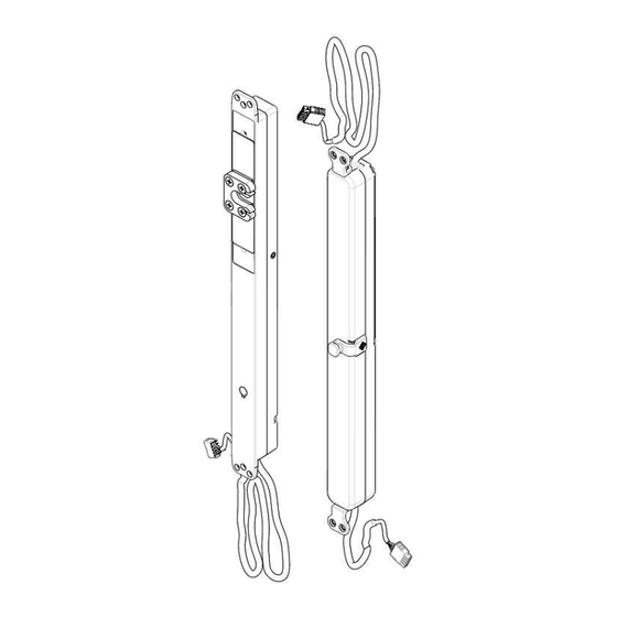
Queste le quote e le dimensioni in sezione dell’attuatore. 6. PROGRAMMAZIONE DEL RADIOCOMANDO 1. togliere il tappo nero di gomma (T) (vedi fig. sotto); 2. selezionare nel radiocomando il canale desiderato; 3. si agisce sul dip-switch 1 che si trova in OFF; 4. - Page 8 Nel caso in cui per errore si selezionano due o più dip-switch in ON, l’attuatore prende la corsa più corta selezionata. Attenzione. L’attuatore viene fornito con corsa minima 160mm. Selezionare le corse in base al braccio utilizzato: A3550L.22/A3400L.22 = Max 160mm A3550L.21/A3400L.21 = Max 100mm Fine corsa in chiusura Il fine corsa in chiusura è...
-
Page 9: Sezione 2 - Wilock
SEZIONE 2 : W 1. DATI TECNICI Modello WiLock Forza di spinta e trazione 600N Forza di spinta e trazione allo spunto 850N Corse 18mm / 36mm (± 1mm) Tensione di alimentazione (20,4÷30V) Assorbimento di corrente a carico nominale 1,4 A Potenza assorbita a carico nominale ~ 32 W Velocità... -
Page 10: Costruzione E Riferimenti Normativi
3. COSTRUZIONE E RIFERIMENTI NORMATIVI La serratura elettromeccanica è stata progettata, costruita e certificata in conformità con marchio Quote di massima dell’attuatore elettrico lineare Rischio di shock elettrico. Rispettare le norme per l’installazione elettrica. Il collegamento elettrico deve rispettare le norme in vigore sulla progettazione e realizzazione degli impianti elettrici. -
Page 11: Operazioni Di Emergenza O Malfunzionamento
5. OPERAZIONI DI EMERGENZA O MALFUNZIONAMENTI Questa operazione in caso di avaria, necessita di una “chiave apposita” (vedi fig. a dx) per trasmettere il moto ad un ingranaggio interno alla serratura. La chiave non è in dotazione ma va richiesta separatamente (Art. -
Page 12: Protezione Ambientale
EXTRA UE l’assistenza verrà effettuata esclusivamente in remoto. La gestione del componente difettoso (eventuale ripristino o sostituzione) verrà effettuata entro i 30 giorni lavorativi dalla data di consegna in Master. La stessa è valida se l’acquirente sia stato in grado di esibire la prova d’acquisto ed abbia soddisfatto le condizioni di pagamento pattuite. - Page 13 INSTRUCTION hazards for the environment. The automatic system WiCloud AR described in this manual is intended to move tilt-and-turn windows or the like. Any use for applications other than those indicated must be authorized by the manufacturer upon technical verification of the assembly.
-
Page 14: General Safety Guidelines
GENERAL SAFETY GUIDELINES CAUTION Before beginning to install this machine, carefully read and understand the following safety guidelines. The installation of the device must be carried out by skilled and qualified technical personnel. Plastic bags, polystyrene, small metal parts such as nails, staples, etc. must not be left within the reach of children as they represent potential hazards. -
Page 15: Section 1 - Wicloud Ar
1 - W ECTION LOUD 1. TECHNICAL DATA Model WiCloud AR Compression and tensile force 200N Strokes 80, 100, 160mm Power supply voltage Current absorbed at nominal load 0.32A Power absorbed at nominal load 7.5W No-load traverse speed 8mm/s No-load stroke time (215 mm) -
Page 16: Formulas And Recommendations For Installation
3. FORMULAS AND RECOMMENDATIONS FOR INSTALLATION Calculation of the opening / closing force Symbols used for the calculation F (kg) = Opening or closing force P (kg) = Weight of the window (movable sash only) C (mm) = Opening stroke (actuator stroke) H (cm) = Height of the movable sash F = 0.54 x P x C : H (Any wind load, favorable or unfavorable on... - Page 17 Electricity mains connection wiring diagram Pos.1 Black “1”, connected to the + (positive); Pos.2 Black “2”, connected to the - (negative); Pos.3 Black “3”, connected (see figure below); Pos.4 sensor and latch connection Pos.5 sensor connection For the command with "Switch": ...
-
Page 18: Programming The Radio Remote Control
The length and cross-section dimensions of the actuator are shown below. 6. PROGRAMMING THE RADIO REMOTE CONTROL 7. remove the black rubber plug (T) (see fig. below); 8. select the desired channel on the radio remote control; 9. operate on dip-switch 1 which is in the OFF position; move it to the ON position for about 1 second and then reposition it on OFF. - Page 19 If two or more dip-switches are accidentally set to ON, the actuator uses the shortest of the selected strokes. Attention. The actuator is supplied with a minimum stroke 80mm. Setting the stroke based on the arm used: A3550L.22/A3400L.22 = Max 160mm A3550L.21/A3400L.21 = Max 100mm Closing stroke-end The closing stroke-end is automatic and non-settable.
-
Page 20: Section 2 - Wilock
SECTION 2 : W 1. TECHNICAL DATA Model WiLock Compression and tensile force 600N Starting compression and tensile force 850N Strokes 18mm / 36mm (± 1mm) Power supply voltage (20.4÷30V) Current absorbed at nominal load 1.4 A Power absorbed at nominal load ~ 32 W No-load speed ~ 8 mm/s... -
Page 21: Construction And Regulatory References
3. CONSTRUCTION AND REGULATORY REFERENCES The electromechanical lock has been designed, manufactured and certified in conformity with mark. General dimensions of the linear electrical actuator Risk of electric shock. Comply with the standards for electrical installation. The electrical connection must comply with current standards on the design and implementation of electrical systems. -
Page 22: Emergency Operations Or Malfunction
5. EMERGENCY OPERATIONS OR MALFUNCTIONS This operation, to be used in case of failure, requires a "special key" (see fig. to the right) to transmit the motion to a gear inside the lock. The key is not included and should be requested separately (Item 1121.54). -
Page 23: Environmental Protection
If any functioning problem occur within this period, on motors purchased in EU, Master can accept a return for inspection purpose. Master will reserve the right to examine the problem and reply within 30 days since returns receiving. Master will agree the eventual repair or replacement consequently. - Page 24 NOTE: …………………………………………………………………………………………………………………… …………………………………………………………………………………………………………………… …………………………………………………………………………………………………………………… …………………………………………………………………………………………………………………… …………………………………………………………………………………………………………………… …………………………………………………………………………………………………………………… …………………………………………………………………………………………………………………… …………………………………………………………………………………………………………………… …………………………………………………………………………………………………………………… …………………………………………………………………………………………………………………… …………………………………………………………………………………………………………………… …………………………………………………………………………………………………………………… …………………………………………………………………………………………………………………… …………………………………………………………………………………………………………………… …………………………………………………………………………………………………………………… …………………………………………………………………………………………………………………… …………………………………………………………………………………………………………………… …………………………………………………………………………………………………………………… …………………………………………………………………………………………………………………… …………………………………………………………………………………………………………………… …………………………………………………………………………………………………………………… …………………………………………………………………………………………………………………… …………………………………………………………………………………………………………………… …………………………………………………………………………………………………………………… …………………………………………………………………………………………………………………… …………………………………………………………………………………………………………………… Pagina 24...
- Page 25 Pagina 25...
Need help?
Do you have a question about the WiCloud AR and is the answer not in the manual?
Questions and answers