Table of Contents
Advertisement
Quick Links
Advertisement
Table of Contents

Related Manuals for Masimo O3


Summary of Contents for Masimo O3
- Page 1 O3™ Regional Oximeter Operator's Manual...
- Page 3 , including display details as well as accessing and changing user-configurable settings. For additional information related to Root, refer to the Operator's Manual for Root. For additional information related to O3 Sensor, refer to the Directions for Use for O3 Sensor...
-
Page 5: Table Of Contents
Unpacking and Inspecting the System ------------------------------------------------------------- 17 Preparation for Use ------------------------------------------------------------------------------------ 17 Connecting the O3 Module to Root ----------------------------------------------------------------- 17 Connecting the O3 Sensor(s) to the O3 Module -------------------------------------------------- 19 Chapter 4: Operation -------------------------------------------------------------------------------------- 21 Regional Oxygenation Information ----------------------------------------------------------------- 21... - Page 6 Regulatory Symbols ----------------------------------------------------------------------------------- 39 Guidance and Manufacturer's Declarations ------------------------------------------------------- 40 Chapter 8: Service and Maintenance ------------------------------------------------------------------ 43 Cleaning Procedure ------------------------------------------------------------------------------------ 43 General Maintenance for O3 Module --------------------------------------------------------------- 43 Service Instructions ----------------------------------------------------------------------------------- 43 Repair Policy -------------------------------------------------------------------------------------------- 44 Return Procedure -------------------------------------------------------------------------------------- 44 Contacting Masimo ------------------------------------------------------------------------------------ 44 Sales &...
-
Page 7: About This Manual
This manual explains how to set up and use the O3 Module. Important safety information relating to general use of the O3 Module appears in this manual. Read and follow any warnings, cautions, and notes presented throughout this manual. The following are explanations of warnings, cautions, and notes. -
Page 9: Product Description
Indications for Use The Masimo O3 Regional Oximeter and Sensors are indicated for the continuous noninvasive monitoring of regional hemoglobin oxygen saturation of blood (rSO2) in the tissue below the sensor, and the noninvasive monitoring of functional oxygen saturation of arterial hemoglobin (SpO2) in hospital and hospital-type facilities. -
Page 11: Safety Information, Warnings And Cautions
WARNING: Do not adjust, repair, open, disassemble, or modify the O3 Module. Injury to personnel or equipment damage could occur. WARNING: Do not start or operate the O3 Module unless the setup was verified to be correct. WARNING: Do not use O3 Module during magnetic resonance imaging (MRI) or in an MRI environment. - Page 12 Improperly applied sensor. • Incorrect sensor type • Adjacent placement of any sensor that is not connected to the same O3 Module . WARNING: For patients experiencing complete bilateral ECA occlusion, rSO2 measurements may be lower than expected. WARNING: When in Pulsatile mode, no SpO2 alarms are provided. Do not use the SpO2 value and trend for continuous patient monitoring;...
-
Page 13: Cleaning And Service Warnings And Cautions
WARNING: A functional tester cannot be used to assess the accuracy of the O3 Module. CAUTION: Do not submerge the O3 Module in any cleaning solution or attempt to sterilize by autoclave, irradiation, steam, gas, ethylene oxide or any other method. This will seriously damage the O3 Module. -
Page 14: Compliance Warnings And Cautions
CAUTION: Disposal of product - Comply with local laws in the disposal of the device and/or its accessories. CAUTION: For FCC compliance information, refer to the Operator's Manual for Root. Note: Use the O3 Module in accordance with the Environmental Specifications section in the Operator's Manual. www.masimo.com... -
Page 15: Chapter 1: Technology Overview
Shallow Detector, and the one farther from the emitters, the Deep detector. This is because the optical signal received at the shallow detector travels through relatively superficial (shallow) sections of tissue, and the optical signal received at the deep detector www.masimo.com Masimo... - Page 16 O3 Regional Oximeter Chapter 1: Technology Overview travels deeper into the tissue, in addition to passing through superficial layers. Deep tissue oxygenation can therefore be calculated by subtracting the effects of shallow tissue from deep tissue via manipulating signals received at the deep and shallow detectors.
-
Page 17: Chapter 2: System Description
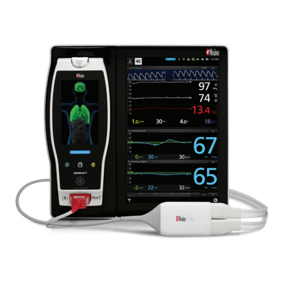
Chapter 2: System Description The O3 Module system is comprised of three (3) components: • Root • O3 Module • O3 Sensor(s) Root Root displays parameters and trends that relate to regional oxygen saturation (rSO2) as well as functional oxygen saturation in the forehead (SpO2). -
Page 18: O3 Module And O3 Sensor
Sensor. The module is powered by Root and also connects Root to the sensor. The O3 Sensor is comprised of a single emitter and two detectors. It is a single-patient use adhesive sensor. For more information about the O3 Sensor, see Directions for Use for the O3 Sensor. -
Page 19: Chapter 3: Setting Up O3 Module
Chapter 3: Setting Up O3 Module For initial use of O3 Module, the following setup instructions must be followed. Unpacking and Inspecting the System Remove the components from the shipping carton and examine them for signs of shipping damage. Check all materials against the packing list. Save all packing materials, invoice and bill of lading. - Page 20 Root with all parameters and measurements dashed out because no O3 Sensor has been connected to the module. For more information on the O3 Module window, see The O3 Module Window on page 22. Repeat the steps above for the second module if more than two sensors are intended to be used.
-
Page 21: Connecting The O3 Sensor(S) To The O3 Module
2 is defaulted to the right forehead. The sensor site selection can be modified by accessing the Site Selection menu. See The O3 Module Window on page 22 for information on how to access the Site Selection menu. -
Page 23: Chapter 4: Operation
Chapter 4: Operation The following sections describe how O3 Module information is displayed when used with Root, including display details and user-configurable settings. For additional information on Root, see Operator’s Manual for Root. Regional Oxygenation Information Regional Oxygenation (rSO2) rSO2, measured in percentage (0 to 100%), is the regional tissue oxygenation level in the deep tissue local to the sensor site. -
Page 24: Functional Oxygenation Information
Delta SpO2 (ΔSpO2) ΔSpO2, displayed as a percentage, is the calculated difference between rSO2 and SpO2. Source of SpO2 can either be forehead SpO2 (using O3 Sensor) or peripheral SpO2 (using pulse oximeter, if available), depending on user selection. Functional Oxygenation Information The following feature is displayed only when the Pulsatile Mode option is enabled. - Page 25 O3 Regional Oximeter Chapter 4: Operation At the top-right corner of each O3 Module window, there is a drop-down menu which allows you to easily change the mode, display options and access the site selection and set baseline menus for each O3 Sensor.
- Page 26 Trend View is the default viewing option for an O3 window. The trend view displays rSO2 trends. This view offers two sensor displays for the two O3 Sensors that can connect to the module, as illustrated in the image below. Note that each sensor display is distinguished by the Sensor Label on the top left corner of each window.
- Page 27 O3 Regional Oximeter Chapter 4: Operation Each sensor display shows a multitude of information about O3 Module parameters and measurements and also allows the user to customize how the information is displayed. The various portions of a sensor display are outlined in the illustration and each portion is explained in more detail in the table below.
- Page 28 ΔSpO2% peripheral SpO2 sensor site) and rSO2 of the O3 Sensor site. Press the value to access the Delta SpO2 menu. User can select either O3 Sensor site or peripheral SpO2 sensor as the source of Delta SpO2. O3 SpO2% Displays the current SpO2 level (O3 Sensor site).
- Page 29 Press the Gear icon on the lower right corner of the main window of Root to access the Main Menu, then press the O3 icon to access the O3 Module Menu and select the Set Baseline menu. In the Set Baseline menu, select Enable. Press Ok to confirm and press the Home button to return to the Main Window.
- Page 30 Chapter 4: Operation Site Selection Menu When the connector end on the O3 Sensor is first inserted into the O3 Module, 1 is defaulted to the left forehead and 2 is defaulted to the right forehead. The sensor site selection can be modified by accessing the Site Selection menu.
-
Page 31: Display And Alarm Settings
Press the Gear icon on the lower right corner of the main window to access the Main Menu. Then press the O3 icon to access the O3 menu. In the O3 menu select the POD icon to access the sensor menu. Press the appropriate O3 Sensor for which to configure specific parameter display and alarm settings. - Page 32 O3 Regional Oximeter Chapter 4: Operation Trend Option Description Factory Configuration Default Options Y-Axis Maximum rSO2 level displayed in Trends 100% 5% to 100% area. Y-Axis Minimum rSO2 level displayed in Trends 0 to 95% area. Additional Settings Option Description...
- Page 33 Additional Settings Option Description Factory Configuration Default Options NORM, MAX, Sensitivity* Sensitivity level at which O3 Module will operate. APOD APOD For more information about sensitivity, refer to the www.masimo.com Masimo...
- Page 34 Delta SpO2 (ΔSpO displayed as a percentage, is the calculated difference between rSO2 and SpO2 Source of SpO2 can either be forehead SpO2 (using O3 Sensor) or peripheral SpO2 (using pulse oximeter, if available), depending on user selection. SpO2 Delta Source...
-
Page 35: Chapter 5: Errors And Alarms
Chapter 5: Errors and Alarms Exception Messages The table below lists the types of messages that can appear on Root when using O3 Module. Exception Message Indication Regional Oximeter The O3 Moduleis not connected to Root or has been disconnected Disconnected from Root. -
Page 36: Alarms Messages
O3 Regional Oximeter Chapter 5: Errors and Alarms Alarms Messages The table below lists the types of alarms that can appear on Root when using O3 Module. Alarm Message Indication Low rSO2 rSO2 level is below low limit. High rSO2 rSO2 level is above high limit. -
Page 37: Chapter 6: Troubleshooting
Chapter 6: Troubleshooting To troubleshoot issues with Root, see the Operator's Manual for Root. To troubleshoot issues with O3 Sensor, see the Directions for Use for the O3 Sensor. If a problem persists, contact an Authorized Masimo Representative. Troubleshooting O3 Module... - Page 38 O3 Regional Oximeter Chapter 6: Troubleshooting Message Possible Cause Action Displayed O3 Sensor may be Replace O3 Sensor. defective. O3 Module may be Replace O3 Module. defective. www.masimo.com Masimo...
-
Page 39: Chapter 7: Specifications
Parameter Range Resolution rSO2 0 to 100% 0 to 100% SpO2 0 to 100% ΔSpO2 0 to 60% Δbase Measurement Accuracy Measurement rSO2 (trending) 3% (from 45% to 85% SavO2) rSO2 (absolute) 4% (from 45% to 85% SavO2) www.masimo.com Masimo... -
Page 40: Environment
O3 Regional Oximeter Chapter 7: Specifications Environment Module Operating Conditions Item Description Temperature at ambient humidity 32˚F to 104˚F (0˚C to 40˚C) Operational Humidity 10% to 95%, non-condensing Module Storage and Shipping Conditions Item Description Temperature at ambient humidity -40˚F to 158˚F (-40˚C to 70˚C) -
Page 41: Regulatory Symbols
O3 Regional Oximeter Chapter 7: Specifications Regulatory Symbols The following symbols are on the product hardware or packaging. Symbol Description Follow instructions for Use. Consult Instructions for Use Separate collection for electronic waste. Mark of conformity to European Medical Device Directive 93/42/EEC. -
Page 42: Guidance And Manufacturer's Declarations
O3 Regional Oximeter Chapter 7: Specifications Symbol Description Manufacturer. Non-sterile. Type BF Applied Part. IPX1 IPX1 Protection against liquid drops falling vertically. Catalog number (model number). Serial Number Guidance and Manufacturer's Declarations Safety Classifications Type of Protection against Electric Shock of the Module... - Page 43 Equipment not suitable for use in the presence of a flammable anesthetic mixture with air, or with oxygen or nitrous oxide. Mode of Operation of O3 Module Continuous: The O3 Module may be operated under normal load for an unlimited period, without the specified limits of temperature being exceeded. Safety Compliance...
-
Page 45: Chapter 8: Service And Maintenance
Chapter 8: Service and Maintenance Cleaning Procedure Cleaning of the O3 Module should be performed at regular intervals or in accordance with hospital, as well as local and governmental regulations. See Safety Information, Warnings and Cautions on page 9 O3 Module is a reusable instrument. The instrument is supplied non-sterile. -
Page 46: Repair Policy
Cleaning Procedure on page 43. Make sure the equipment is fully dry before packing. To return the O3 Module for service, please follow the Return Procedure on page 44. Return Procedure Clean contaminated/dirty equipment before returning, following instructions in Cleaning Procedure section. -
Page 47: Sales & End-User License Agreement
Masimo for a full refund. Warranty Masimo warrants to the initial Purchaser for a period of one (1) year from the date of purchase that: each new Product and the Software media as delivered are free from defects in workmanship or materials. -
Page 48: Restrictions
Ownership of Software: The Software is licensed not sold; all rights and interests in the Software and all copies thereof remain at all times vested in Masimo, and do not pass to Purchaser. Any references in this Agreement to the purchase or sale of the Software shall be deemed the purchase or sale of a Software License as set forth herein. -
Page 49: Index
No Implied License • 46 Service and Maintenance • 43 Cleaning Procedure • 43, 44 Connecting the O3 Module to Root • 17 Connecting the O3 Sensor(s) to the O3 O3 Module and O3 Sensor • 16 Module • 19 O3 Module Viewing Modes •... - Page 50 43, 45 Service Instructions • 43 Site Selection Menu • 28 SpO2 Settings • 31 The O3 Module Window • 18, 19, 22 Trend View • 24 Troubleshooting O3 Module • 35 Unpacking and Inspecting the System • Warranty • 45 www.masimo.com...
- Page 52 36579/LAB-7910D 0914...
Need help?
Do you have a question about the O3 and is the answer not in the manual?
Questions and answers