Table of Contents
Advertisement
Quick Links
Advertisement
Table of Contents

Related Manuals for Masimo O3


Summary of Contents for Masimo O3
- Page 1 Operator's Manual O3™ Regional Oximeter...
- Page 3 O3™ Regional Oximeter System (O3 System) which consists of the O3 Module and O3 Sensor. There may be information provided in this manual that is not relevant for your system. General knowledge of pulse oximetry and an understanding of the features and functions of the O3™...
-
Page 5: Table Of Contents
Unpacking and Inspecting the System ------------------------------------------------------------- 19 Preparation for Use ------------------------------------------------------------------------------------ 19 Connecting the O3 Module to Root ----------------------------------------------------------------- 19 Connecting the O3 Sensor(s) to the O3 Module -------------------------------------------------- 21 Chapter 4: Operation -------------------------------------------------------------------------------------- 23 Regional Oxygenation Information ----------------------------------------------------------------- 23... - Page 6 Guidance and Manufacturer's Declarations ------------------------------------------------------- 45 Citations ------------------------------------------------------------------------------------------------- 46 Chapter 8: Service and Maintenance ------------------------------------------------------------------ 47 Cleaning Procedure ------------------------------------------------------------------------------------ 47 General Maintenance for O3 Module --------------------------------------------------------------- 47 Service Instructions ----------------------------------------------------------------------------------- 47 Repair Policy -------------------------------------------------------------------------------------------- 48 Return Procedure -------------------------------------------------------------------------------------- 48 Contacting Masimo ------------------------------------------------------------------------------------ 49 Sales &...
-
Page 7: About This Manual
About this Manual This manual explains how to set up and use the O3 System, which consists of the O3 Module and O3 Sensor. Important safety information relating to general use of the O3 System appears in this manual. Read and follow any warnings, cautions, and notes presented throughout this manual. -
Page 9: Product Description
The O3 System should not be used as the sole basis for diagnosis or therapy. Indications for Use The noninvasive Masimo O3™ Regional Oximeter System and accessories are intended for use... -
Page 11: Safety Information, Warnings And Cautions
WARNING: Do not adjust, repair, open, disassemble, or modify the O3 Module. Injury to personnel or equipment damage could occur. WARNING: Do not start or operate the O3 Module unless the setup was verified to be correct. WARNING: Do not use O3 Module during magnetic resonance imaging (MRI) or in an MRI environment. -
Page 12: Performance Warnings And Cautions
WARNING: The O3 Module may be used during electrocautery, but this may affect the accuracy or availability of the parameters and measurements. WARNING: The O3 Module may be used during defibrillation, but this may affect the accuracy or availability of the parameters and measurements. - Page 13 CAUTION: Check the sensor site periodically for circulatory status. Each patient’s sensitivity to the O3 sensors may vary depending on their medical status or condition of their skin. Note: The value of data from the system has not been demonstrated in specific disease states, under conditions of hemoglobinopathies or clinical conditions that may affect blood volume, or under hypocapnic and hypercapnic conditions.
-
Page 14: Cleaning And Service Warnings And Cautions
WARNING: A functional tester cannot be used to assess the accuracy of the O3 Module. CAUTION: Do not submerge the O3 Module in any cleaning solution or attempt to sterilize by autoclave, irradiation, steam, gas, ethylene oxide or any other method. This will seriously damage the O3 Module. -
Page 15: Chapter 1: Technology
Chapter 1: Technology The principle of operation for the O3 Regional Oximeter System (O3 System) is as follows: Overview The O3 System’s operating principle is based on multi-distance diffuse reflectance spectroscopy. The O3 System uses light to examine a cross-section tissue microvasculature (a mixed bed of arterioles, capillaries, and venules) and analyzes the light returned after having passed through the tissues. - Page 16 Figure 1: Absorption coefficients of tissue chromophores in the NIR spectrum* Masimo’s regional oximeter consists of a light emitter and multiple detectors. By emitting multiple wavelengths of light (LEDs), which pass through the region of interest, and measuring them (using photo-detectors) after they have traveled through the tissue, the system calculates attenuation experienced by each wavelength.
-
Page 17: Components Of The Regional Oximetry System
O3 Regional Oximeter Chapter 1: Technology Components of the Regional Oximetry System The regional oximetery system uses a common emitter and at least two detectors that are spaced apart from each other and are at different distances relative to the emitter. In the case of a two-detector system, as in Figure 2, the detectors may be known as: •... -
Page 19: Chapter 2: System Description
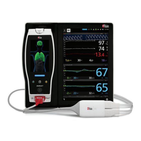
Chapter 2: System Description The O3™ Regional Oximeter System (O3 System) is comprised of three (3) components: • Root • O3 Module • O3 Sensor(s) Up to two O3 Sensors can be connected to a single O3 Module. Up to two O3 Modules can be connected to Root. -
Page 20: O3 Module And O3 Sensor
O3 sensor connects into the O3 module directly. In the other version, the connection is integrated within the O3 module on one end and the other end has a connection for the O3 sensor(s). -
Page 21: Chapter 3: Setting Up The O3 System
Chapter 3: Setting Up the O3 System For initial use of O3 System, the following setup instructions must be followed. Unpacking and Inspecting the System Remove the components from the shipping carton and examine them for signs of shipping damage. - Page 22 Root with all parameters and measurements dashed out because no O3 Sensor has been connected to the module. For more information on the O3 Module window, see The O3 Module Window on page 25. Repeat the steps above for the second module if more than two sensors are intended to be used.
-
Page 23: Connecting The O3 Sensor(S) To The O3 Module
Chapter 3: Setting Up the O3 System Connecting the O3 Sensor(s) to the O3 Module Up to two (2) sensors can be connected to each O3 module. The two (2) connections are symmetrical in orientation and clearly marked “1” and “2” on the module. - Page 24 2 is defaulted to the right forehead. The sensor site selection can be modified by accessing the Site Selection menu. See The O3 Module Window on page 25 for information on how to access the Site Selection menu.
-
Page 25: Chapter 4: Operation
Chapter 4: Operation The following sections describe how O3 Module information is displayed when used with Root, including display details and user-configurable settings. For additional information on Root, see Operator’s Manual for Root. Regional Oxygenation Information Regional Oxygenation (rSO2) , measured in percentage (0 to 99%), is the regional tissue oxygenation level in the deep tissue local to the sensor site. - Page 26 Source of SpO2 is from peripheral SpO2 (using pulse oximeter, if available), depending on user selection. Peripheral SpO2 measurements are not provided by the O3 Module. The measurements are provided by another device such as the Masimo pulse oximetry technology.
-
Page 27: The O3 Module Window
When an O3 Module is connected to Root, O3 Module parameters and measurements display in the O3 Module window as numeric values with graphical representations. Each O3 Sensor connected will generate a separate O3 Module window, with the Sensor Label displayed in the name of the window. - Page 28 Trend View is the default viewing option for an O3 window. The trend view displays rSO trends. This view offers two sensor displays for the two O3 Sensors that can connect to the module, as illustrated in the image below. Note that each sensor display is distinguished by the Sensor Label on the top left corner of each window.
- Page 29 O3 Regional Oximeter Chapter 4: Operation Each sensor display shows a multitude of information about O3 Module parameters and measurements and also allows the user to customize how the information is displayed. The various portions of a sensor display are outlined in the illustration and each portion is explained in more detail in the table below.
- Page 30 Displays the difference between levels of SpO2 (peripheral SpO2 ΔSpO2% sensor site) and rSO of the O3 Sensor site. Displays the Area Under the Curve cumulative index. Timeline Displays timestamps and corresponding date. Displays the current difference between levels of rSO and selected Δbase%...
- Page 31 Press the Gear icon on the lower right corner of the main window of Root to access the Main Menu, then press the O3 icon to access the O3 Module Menu and select the Set Baseline menu. In the Set Baseline menu, select Enable. Press Ok to confirm and press the Home button to return to the Main Window.
- Page 32 Other Body Sensor Sites selections are for reference only and are not intended for patient monitoring. When the connector end on the O3 Sensor is first inserted into the O3 Module, 1 is defaulted to the left forehead and 2 is defaulted to the right forehead. The sensor site selection can be modified by accessing the Site Selection menu.
- Page 33 O3 Regional Oximeter Chapter 4: Operation Head Patient View Head is the default view when Site Selection is displayed. Ref Description Choose either sensor 1 then sensor 2 to change sensor site location. Only the selected sensor location can be changed.
- Page 34 O3 Regional Oximeter Chapter 4: Operation Body Sensor Sites Select Body in the upper left corner of the screen to switch to the Body Sensor Sites locations display. Ref Description Current location of sensor 1 and sensor 2 (Head). Choose either the Sensor 1 or Sensor 2 button to select the sensor and change sensor site location.
-
Page 35: Display And Alarm Settings
Press the Gear icon on the lower right corner of the main window to access the Main Menu. Then press the O3 icon to access the O3 menu. In the O3 menu select the POD icon to access the sensor menu. Press the appropriate O3 Sensor for which to configure specific parameter display and alarm settings. - Page 36 O3 Regional Oximeter Chapter 4: Operation Trend Option Description Factory Configuration Default Options Y-Axis Maximum rSO level displayed in Trends 100% 5% to 100% area. Y-Axis Minimum rSO level displayed in Trends 0 to 95% area. Additional Settings Option Description...
- Page 37 O3 Regional Oximeter Chapter 4: Operation Delta Baseline (Δbase) Settings The following are the various setting options for Delta Baseline: About An informational read-only screen appears with the following definition for Delta Baseline Settings: Relative deficit below baseline displayed as a percentage of the baseline rSO...
- Page 38 Delta SpO2 (ΔSpO2), displayed as a percentage, is the calculated difference between rSO and SpO2. Source of SpO2 is from peripheral SpO2 (using pulse oximeter, if available). Peripheral SpO2 measurements are not provided by the O3 Module. The measurements are provided by another device such as the Masimo pulse oximetry technology.
-
Page 39: Chapter 5: Errors And Alarms
Chapter 5: Errors and Alarms Exception Messages The table below lists the types of messages that can appear on Root when using O3 Module and O3 Sensor. Exception Message Indication Regional Oximeter The O3 Module is not connected to Root or has been disconnected Disconnected from Root. -
Page 40: Alarms Messages
O3 Regional Oximeter Chapter 5: Errors and Alarms Alarms Messages The table below lists the types of alarms that can appear on Root when using O3 Module. Alarm Message Indication Low rSO level is below low limit. High rSO level is above high limit. -
Page 41: Chapter 6: Troubleshooting
Chapter 6: Troubleshooting To troubleshoot issues with Root, see the Operator's Manual for Root. To troubleshoot issues with O3 Sensor, see the Directions for Use for the O3 Sensor. If a problem persists, contact an Authorized Masimo Representative. Troubleshooting O3 Module... - Page 42 O3 Regional Oximeter Chapter 6: Troubleshooting Message Possible Cause Action Displayed O3 Sensor may be Replace O3 Sensor. defective. O3 Module may be Replace O3 Module. defective. www.masimo.com Masimo...
-
Page 43: Chapter 7: Specifications
(absolute) [3] 4% (from 45% to 85% SavO2) * The A Accuracy is calculated based upon measurement values that are statistically distributed; approximately 68% of the measured values fell within +/- the A value when compared to the reference device under a controlled study. www.masimo.com Masimo... -
Page 44: Environment
O3 Regional Oximeter Chapter 7: Specifications Environment Module Operating Conditions Item Description Temperature at ambient humidity 32˚F to 104˚F (0˚C to 40˚C) Operational Humidity 10% to 95%, non-condensing Module Storage and Shipping Conditions Item Description Temperature at ambient humidity -40˚F to 158˚F (-40˚C to 70˚C) -
Page 45: Symbols
O3 Regional Oximeter Chapter 7: Specifications Symbols The following symbols are on the product hardware or packaging. Symbol Description Follow instructions for Use Consult Instructions for Use Separate collection for electronic waste Mark of conformity to European Medical Device Directive 93/42/EEC... - Page 46 O3 Regional Oximeter Chapter 7: Specifications Symbol Description Caution Date of Manufacture Manufacturer Non-sterile Type BF Applied Part IPX1 IPX1 Protection against liquid drops falling vertically Catalog number (model number) Serial Number Instructions/Directions for Use/Manuals are available in electronic format @http://www.Masimo.com/TechDocs...
-
Page 47: Guidance And Manufacturer's Declarations
Equipment not suitable for use in the presence of a flammable anesthetic mixture with air, or with oxygen or nitrous oxide. Mode of Operation of O3 Module Continuous: The O3 Module may be operated under normal load for an unlimited period, without the specified limits of temperature being exceeded. Safety Compliance... -
Page 48: Citations
45% to 85% SavO2 against 30% arterial and 70% jugular venous blood oxygen saturations, measured by a laboratory CO-Oximeter. The study confirms that the O3 System measurements meet the requirements. [2] Trending accuracy is the root mean square relative error. It is calculated by comparing a series of samples to the gold standard and the accuracy refers to how the changes in a series of samples “trend”... -
Page 49: Chapter 8: Service And Maintenance
Chapter 8: Service and Maintenance Cleaning Procedure Cleaning of the O3 Module should be performed at regular intervals or in accordance with hospital, as well as local and governmental regulations. See Safety Information, Warnings and Cautions on page 9. O3 Module is a reusable instrument which is supplied non-sterile. -
Page 50: Repair Policy
Cleaning Procedure on page 47. Make sure the equipment is fully dry before packing. To return the O3 Module for service, please follow the Return Procedure on page 48. Return Procedure Clean contaminated/dirty equipment before returning, following instructions in Cleaning Procedure section. -
Page 51: Contacting Masimo
Masimo for a full refund. Warranty Masimo warrants to the initial Purchaser for a period of one (1) year from the date of purchase that: each new Product and the Software media as delivered are free from defects in workmanship or materials. -
Page 52: End-User License
Products or Software. In no event shall Masimo’s liability arising from any Product and Software (under contract, warranty, tort, strict liability or other claim) exceed the amount paid by purchaser for the Products giving rise to such claim. -
Page 53: No Implied License
O3 Regional Oximeter Chapter 8: Service and Maintenance party that legally acquires title to the Product with which this Software is included. Any attempt to assign any rights, duties or obligations arising hereunder other than as set forth in this paragraph shall be void. -
Page 55: Index
Environment • 42 System Description • 17 Exception Messages • 37 Chapter 3 Exclusions • 49 Setting Up the O3 System • 19, 39 Chapter 4 Operation • 23 General Maintenance for O3 Module • 47 Chapter 5 Guidance and Manufacturer's Errors and Alarms •... - Page 56 Safety Warnings and Cautions • 9 Sales & End-User License Agreement • 47, 49 Service Instructions • 47 Site Selection Menu • 30 Symbols • 43 The O3 Module Window • 20, 22, 25 Trend View • 26 Troubleshooting O3 Module • 39 www.masimo.com Masimo...
- Page 58 38415/LAB-9358A 0616...
Need help?
Do you have a question about the O3 and is the answer not in the manual?
Questions and answers