
Related Manuals for Meyra TA IQ FWD StandUP


Summary of Contents for Meyra TA IQ FWD StandUP
- Page 1 OPERATING MANUAL TA IQ FWD StandUP This product fulfils the requirements of Regulation (EU) 2017/745 on medical devices. 300-25 UM SU - GB - 06.2021, vers. 1:0.
-
Page 2: Table Of Contents
Use with products from other manufacturers When the electric wheelchair is used by another person Product life span Base position Overview Model TA IQ FWD StandUp Handling and care of the electric wheelchair Securing the wheelchair Operational inspection Driving characteristics... - Page 3 Preparation for use Inspection before driving Charging the battery Position of the control module Description of functions Swing the control module out to the side of the armrest. to drive closer up to a table. Position of the armrest Checking the locking feature Leg supports Footplate Adjusting the footplate height...
- Page 4 Headrest Adjusting the headrest Use of the headrest in disability vehicles Securing bags Safety belt Safety belt Using the safety belt Opening the safety belt Adjusting belt length Lights Transfer and transport Loading/unloading Ramps and lifts Personal transport in motor vehicles Securing the wheelchair for transport Tyres Maintenance...
- Page 5 Operating range Driving characteristics when negotiating gradients Applicable standards Specifications in conformance with ISO 7176-15 for model TA IQ FWD StandUp Supplementary technical data for model TA IQ FWD StandUp Explanation of the labels on the electric wheelchair Explanation of the symbols on the nameplate...
-
Page 6: Symbols Key
These operating instructions apply to the wheelchair for the first time and follow following model: the instructions carefully. Model TA IQ FWD StandUP If children or teenagers will be using the wheelchair, they should first read this INDICATIONS / manual along with their parents or guard- CONTRAINDICATIONS ians before using the chair. -
Page 7: Exit Assistance Function
Exit assistance function When purchasing a particular product, you should furthermore take into account the Seek medical advice immediately for un- disabled individual’s physical and mental expected symptoms that could be associ- condition, age, home living conditions and ated with using the exit assistance. personal circumstances. -
Page 8: Delivery And Arrival
DELIVERY AND ARRIVAL USAGE All products undergo strict quality control Do not use the wheelchair without the procedures at the factory and are packaged assembled leg supports and armrests! in special cardboard boxes. The wheelchair is exclusively intended ☞ Nonetheless, we ask that you, immedi- transport a seated individual –... -
Page 9: Adjustment
ADJUSTMENT USE WITH PRODUCTS FROM OTHER Ensure that any adjustment, configura- MANUFACTURERS tion or repair work is only performed by an authorised distributor. In general, any combination of your electric wheelchair with components not supplied The electric wheelchair can be adjusted by the manufacturer constitutes a mate- to fit individual body sizes. -
Page 10: Product Life Span
PRODUCT LIFE SPAN We estimate that the product should have an expected average life span of 5 years in- sofar as the product is used for the intended purpose and all maintenance and service requirements are adhered to. The product’s life span depends on the frequency of use, the environment where it is utilised and the care that it receives. -
Page 11: Overview
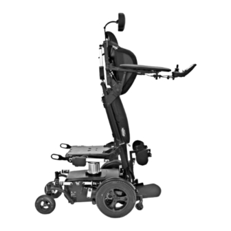
OVERVIEW Model TA IQ FWD StandUp The overview shows the main components and controls of the electric wheelchair. No. Name (1) Headrest (2) Back support (3) Armrest (4) Seat cushion (5) Knee pad (6) Calf support (7) Footplate (8) Anti tip wheel... -
Page 12: Handling And Care Of The Electric Wheelchair
HANDLING AND CARE BRAKES OF THE ELECTRIC Brake your wheelchair carefully and in WHEELCHAIR good time. This applies especially when driving toward people or going downhill! Securing the wheelchair Service brake The electric wheelchair must be secured as follows so that it does not accidentally roll: The electric motors work as a mechanical brake, stopping the wheelchair smoothly 1. -
Page 13: Activating The Brakes
Activating the brakes The wheelchair should not be able to be pushed while the brakes are engaged. To apply the brakes, move the drive/push mode levers on both sides approximately 45° toward the wheelchair chassis and into the drive (upright) position [1]. ☞... -
Page 14: Main Circuit Breakers For All Electrical Functions
Main circuit breakers for all electrical functions As a standard feature, all TA Service wheel- chairs manufactured after 26/05/2021 come equipped with a main circuit breaker for all electrical functions, also known as a Flight kit [3]. Removing the key from the Flight kit allows you to interrupt the wheelchair’s power supply [4]. -
Page 15: Drive/Push Mode
Drive/push mode The electric wheelchair should only be set on push mode or pushed for the sake of manoeuvring or in emergency situations. This should only be done on flat terrain, with the chair in a standstill position. ☞ In push mode, the electromagnetic brakes are deactivated. -
Page 16: Setting The Chair On Drive Mode
Setting the chair on drive mode 1. Activate the brakes [2]. ☞ Follow the instructions in Activating the brakes on page 13. 2. Turn on the control module. ☞ See the ‘Control module’ chapter in the Operating manual. Now the electric wheelchair can be driven. -
Page 17: Preparation For Use
PREPARATION FOR USE Perform the following consecutive steps to prepare your electric wheelchair for use. ☞ Using the control module, charge the batteries before making your first trip. 1. Complete your preparations for driving. Move the levers into drive mode [1] to activate the motors. - Page 18 3. Check the position of the control mod- ule. ☞ For ordinary driving, move the control module forward and inward until it set- tles into the stop position [3]. 4. Turn on the control module. ☞ Depress the on/off button (4) on the control module.
-
Page 19: Inspection Before Driving
Inspection before driving Before driving, you should inspect the fol- lowing: ☞ The charge level of the battery ☞ The configuration of the maximum speed setting – See the ‘Control module’ chapter in the Operating manual. Charging the battery Do not place any objects in the sock- et aside from the battery charger plug! –... - Page 20 3. Turn on the battery charger/plug the battery charger power cord into an ap- propriate socket. ☞ The charging process has now start- ☞ The battery will not charge if the ther- mal fuse is turned off (2)! 4. Once the charging process is complete, disconnect the battery charger from the mains and pull the charger plug out of the control module socket.
-
Page 21: Position Of The Control Module
Position of the control module For ordinary driving, move the control mod- ule forward and inward [1]. Description of functions The push buttons and symbols on the mod- ule are all described in detail in the Operat- ing manual in the ‘Control module’ chapter. Swing the control module out to the side of the armrest. -
Page 22: Leg Supports
LEG SUPPORTS Before using the leg supports, secure the wheelchair against rolling away uninten- tionally. ☞ Follow the instructions in Securing the wheelchair on page 12. The angle of the leg support [1] and the height of the footplate can be adjusted via the control module. -
Page 23: Adjusting The Footplate Height
Adjusting the footplate height When adjusting the height of the foot- plate(s), never touch or handle the adjust- ment mechanism or the underside of the footplate(s). – Risk of a crushing injury! Make sure that the leg support and the footplate(s) have adequate ground clear- ance! ☞... -
Page 24: Knee Pads
KNEE PADS Incorrectly adjusted knee pads can cause knee damage in the standing and reclin- ing position. Check the settings before use and con- tact your authorised service centre if nec- essary. Remove the knee pads before using the exit assistance. Knee pads that have been removed should not be thrown or dropped, but should be treated properly. -
Page 25: Adjusting Knee Pad Clearance
Adjusting knee pad clearance Do not adjust knee pads positioned by the service centre. – Risk of injury! Make sure there is one hand width clear- ance between the leg and the knee pad before you stand up! ☞ Contact your authorised distributor in the event of an unsafe standing position! To adjust the knee pad clearance, first lift up... -
Page 26: Armrests
ARMRESTS Avoid using the armrests [1] to carry or lift the wheelchair. When the armrest is tilted up, move the support tubing (2) up or down. – Risk of injury! Folding up the armrests To fold up an armrest, depress the button lock (3). -
Page 27: Folding Down The Armrests
Folding down the armrests For drive mode, the armrests should be swung forward and down [1]. The armrest’s locking feature Risk of a crushing injury when the armrest engages with the button lock [2]! 1. Swing the armrests forward and down. Move the support tubing downwards and beyond the button lock [2]. -
Page 28: Armrest Angle Adjustment
Armrest angle adjustment The armrest can be adjusted positively [1] or negatively [2] via a telescopic tube. Adjusting the armrest angle There is a risk of a crushing injury when moving the armrest into the lower posi- tion [2]! 1. Pull out the adjusting bolt (3) to adjust the angle of the armrest. -
Page 29: Back Support
BACK SUPPORT Whenever you adjust the back support, always make sure that the electric wheel- chair is on a level surface. Otherwise, there is a risk that the wheelchair may flip over on an incline! The angle of the back support [1] can be ad- justed with the control module. -
Page 30: Seat
SEAT Seat cushions The seat cushion [1] is mounted to the base- plate with a Velcro band and is removable. After cleaning or maintenance, put the seat cushion back on and secure it [1]. – Velcro fastening. Adjusting seating comfort The air pressure can be adjusted for im- proved comfort by opening and closing the valves (2). -
Page 31: Seat Rocker
Seat rocker The seat rocker [3] should only be adjust- ed while the electric wheelchair is on a flat, horizontal surface. There is a risk that the wheelchair flips over on an incline. Put your feet on the footplate before ad- justing the seat angle and move the leg support to the base position. -
Page 32: Seat Lift
Seat lift Make sure that there are no people or obstacles in the area before adjusting the seat height. – Risk of injury! Do not touch or come into contact with the bottom of the seat before or during seat height adjustment. – Risk of a crush- ing injury! Seat height adjustment is only allowed on a flat, level surface. -
Page 33: Stand Up Function
Stand up function Make sure that there are no people or obstacles in the area before standing up. – Risk of injury! The stand up function is only allowed when stationary on a flat, level surface. – The more you stand up, the greater the risk of overturning. - Page 34 ☞ The user should only stand up with the safety belt [1] and correctly adjusted knee pads [2]. ☞ See Safety belt on page 40 and Knee pads on page 24 for more information. ☞ See the ‘Control module’ chapter in the Operating manual for adjustment in- structions.
-
Page 35: Reclining Function
Reclining function Before operating the reclining function, make sure that the surrounding area is free of obstructions. – Risk of injury! The reclining function is only allowed when stationary on a firm, flat, level sur- face. Do not lower the foot plate(s) while the leg support(s) are being lifted out of the base position! The reclining function [1] can be adjusted... -
Page 36: Exit Assistance
Exit assistance Before operating the exit assistance, make sure that the surrounding area is free of obstructions. – Risk of injury! The exit assistance is only allowed when stationary on a firm, flat, level surface. The exit assistance function must not be used unless a thorough demonstration has been provided by the distributor, therapist or product specialist. - Page 37 Proceed as follows to exit the wheelchair: 1. Remove the knee pad, if fitted. ☞ Follow the instructions in Knee pads on page 24. 2. Perform any adjustments. 3. Turn off the wheelchair. ☞ Follow the instructions in Securing the wheelchair on page 12. ☞...
-
Page 38: Headrest
HEADREST The headrest is completely removable and both the height and angle are adjustable. Adjusting the headrest To adjust the height of the headrest or re- move it, loosen [2] the tightening handle (1). Use of the headrest in disability vehicles This headrest is approved for transport in motorised disability vehicles! -
Page 39: Safety Belt
SAFETY BELT Make sure no objects get stuck under the belt! – This prevents unpleasant pressure points. Aftermarket installation of a seat belt must only be done by an authorised re- pair centre. The belt must not be used as a restraint system for securing either the user or the wheelchair during transport in a motor vehicle. -
Page 40: Safety Belt
SAFETY BELT The safety belt must not be used as a re- straint system for securing either the user or the wheelchair during transport in a motor vehicle. Make sure no objects get stuck under the belt! – This prevents unpleasant pressure points. -
Page 41: Opening The Safety Belt
Opening the safety belt To open the safety belt [4], press the release button (2) and pull the ends of the belt away from one another. Adjusting belt length To adjust the belt length, hold the buckle at right angles to the already tightened belt and move it accordingly. -
Page 42: Lights
LIGHTS If used outdoors or on public roads, the electric wheelchair should be equipped with an LED lighting system (1)+(2). The lights can be operated via the control module. ☞ See the ‘Control module’ chapter in the Operating manual. ☞ If visibility is poor, especially in the dark, the lights should be turned on so that you can see better and are more easily seen. -
Page 43: Transfer And Transport
TRANSFER AND TRANSPORT The electric wheelchair must not be lifted by its back support, leg supports, armrest or upholstery! Keep the seat height and seat tilt in the base position during transport! Always turn the electric wheelchair off before lifting it! Loading/unloading Any parts that have been dismantled for loading should be stored in a safe place... -
Page 44: Personal Transport In Motor Vehicles
Personal transport in motor vehicles The nameplate on your electric wheelchair indicates whether the chair is approved as a car seat for motor vehicle transport. ☞ Learn more about this in Explanation of the symbols on the nameplate on page 65. ☞... -
Page 45: Tyres
TYRES The tyres are made of a rubber compound and may leave marks that are difficult or im- possible to remove on some surfaces (incl. synthetic, wood or parquet floors, carpets/ rugs and floor coverings). We disclaim any liability for any damage to surfaces owing to wear and tear or chemical reactions with the tyres. -
Page 46: Service Plan
Service plan WHEN WHAT COMMENT Before driving In general Perform the inspection alone or together with a helper. Check for proper function- ing. Inspecting the electro- Perform the inspection alone magnetic brake or together with a helper. Move the drive/push mode If the electric wheelchair can levers on both sides to the be pushed, then the brake is... - Page 47 WHEN WHAT COMMENT Every 6 months Check See Cleaning on page 54. (depending on how – Cleanliness Perform this alone or together often the wheelchair is with a helper. – Overall condition used) Inspection Manufacturer’s recom- Performed by the distributor. mendation: –...
-
Page 48: Main Fuse
Main fuse The thermal fuse’s fail-safe button must be pushed in. The main fuse consists of a thermal fuse (1) that pops out in the event of a current over- load. If the fuse pops out, it must be pushed in again. -
Page 49: Lights
Lights The bulbs (1) + (2) are long-life LED bulbs. ☞ Any defective LED bulb must be re- paired by an authorised repair shop immediately. Running lights The lights must be adjusted so that the low- er edge of the beam lies approx. 3 metres ahead of the wheelchair with the seat tilt down in the base position. -
Page 50: Troubleshooting
Troubleshooting Malfunction Cause Solution The control module’s bat- The main thermal fuse has Press the thermal fuse back tery indicator does not light popped out. up when switched on. If it pops out again, contact your service workshop for repair. The power plug is not con- Inspect the connectors. -
Page 51: Basic Safety Precautions
BASIC SAFETY In direct sunlight, the seat cover/cushion, PRECAUTIONS armrest cushions, leg supports and han- dles/levers can reach temperatures above 41 °C. – This may injure unprotected skin! These safety precautions are an excerpt Park in the shade to prevent the surfaces of the Safety precautions and general in- on your electric wheelchair from getting structions for use, which is available on our... -
Page 52: Picking Up Objects
Picking up objects The braking force that can be applied to the road is substantially lower when driv- Avoid bending your upper body far forward, ing down a hill compared to driving on a to the side or backwards, especially when level road and deteriorates further if the picking up or setting down heavy objects. -
Page 53: Electrical System
Carriage in public transport Always drive toward smaller obstacles, such as ledges/edges, slowly and at a straight Your electric wheelchair is not designed for angle (90°). Drive forward and approach passenger transit in public transit vehicles. to within approx. 0.5 m of the obstacle so There may be limitations. -
Page 54: Driving On Public Roads
CLEANING Driving on public roads Comply with all national regulations for driv- Non-ionic detergents, solvents and es- ing on public roads and ask your authorised pecially alcohol may react with synthetic distributor about any required accessories. coverings. The electric wheelchair can be delivered Never rinse or pressure rinse your electric with accessory lights. -
Page 55: Treated Surfaces
Disinfection Always keep the lights clean and check that they are functioning properly before driv- If the product is used by multiple individu- ing. als (e.g. at a care institution), ordinary disin- ☞ Always protect the electrical compo- fectant should be used. nents from water and moisture! ☞... -
Page 56: Repairs
REPAIRS Precautions for long-term storage The following precautions are necessary if In principle, repairs should only be per- the wheelchair will not be used for a longer formed by authorised distributors. period of time: ☞ Charge the batteries for 16 hours at Assembly least once a month. -
Page 57: Disposal
DISPOSAL A template for additional inspection docu- mentation can be copied from the Service and maintenance manual as needed. If this is utilised, it should be attached to the Op- erating manual. Programming driving characteristics The electric wheelchair’s driving character- istics can be configured via a programming unit. -
Page 58: Technical Data
TECHNICAL DATA Operating range Our indicated nominal data are realistic, All the information in the ‘Technical data’ provided that ISO 7176-4 is fully complied chapter applies to the standard model. with. Measurement tolerances ±15 mm, ± 2° The operating range largely depends on Calculating the max. -
Page 59: Applicable Standards
Applicable standards The electric wheelchair fulfils the following standards: – EN 12184: 2014 – ISO 7176-8: 2014 – ISO 7176-19: 2008 ☞ Crash test evaluations, where the wheelchair was attached via the vehicle's braking system, were per- formed in accordance with the test- ing methods in Annex D. -
Page 60: Specifications In Conformance With Iso 7176-15 For Model Ta Iq Fwd Standup
Specifications in conformance with ISO 7176-15 for model TA IQ FWD StandUp min. max. Overall length (measured with a 0° seat tilt) 985 mm 1160 mm Overall width 630 mm 720 mm Total weight, max. allowable 320 kg User weight (incl. payload) 140 kg for reclining function 100 kg User weight 136 kg... - Page 61 min. max. Minimum braking distance at top speed 2620 mm Operating range (at 6 km/h) 40 km (depends on battery capacity) Operating range (at 10 km/h and 12 km/h) 35 km (depends on battery capacity) Axle, horizontal position – mm –...
-
Page 62: Supplementary Technical Data For Model Ta Iq Fwd Standup
Supplementary technical data for model TA IQ FWD StandUp min. max. Noise level 70 dB(A) Enclosure class IPX4 Min. turning radius 1170 mm Drive controller output 24 V/120 A Engine output 2 x 350 W Main fuse 80 A Lights (accessory) - Page 63 min. max. Drive wheel Tyres, max. 2.5–3.0 bars 364 x 75 mm diameter (14” x 3.5”) (33 -44 psi/250 kPa) puncture-proof Batteries 2 x 12 V 75 Ah (5 h) / 80Ah (20 h) Enclosed, maintenance-free Max. battery dimensions (L x W x H) 260 x 168 x 215 mm Charging current...
-
Page 64: Explanation Of The Labels On The Electric Wheelchair
Explanation of the labels on the electric wheelchair Attention! Read the Operating manual and attached documentation. Do not lift the electric wheelchair by the armrests or leg supports. Do not lift the wheelchair by any detachable parts. Drive mode Push mode Only push the wheelchair on a level surface. -
Page 65: Explanation Of The Symbols On The Nameplate
Explanation of the symbols on the nameplate Manufacturer Order number Serial number Date of production Allowable user weight Allowable total weight Allowable axle pressure Allowable upward gradient Allowable downward gradient Max. allowable speed The product is approved for use as a car seat. Max. -
Page 66: Explanation Of The Washing Instruction Symbols
Explanation of the washing instruction symbols (The symbols are in compliance with European standards.) Wash on gentle cycle at the maximum indicated temperature (°C). Wash on normal cycle at the maximum indicated temperature (°C). Hand wash only. Do not bleach. Not suited for the dryer. -
Page 67: Documentation Of Servicing
DOCUMENTATION OF Recommended safety inspection: 1st year (after no later than 12 months) SERVICING Stamp of speciality dealer: Vehicular data: Model: Signature: Packing slip no.: Location, date: Serial no. (SN): Next safety inspection in 12 months Date: Recommended safety inspection: 2nd year Recommended safety inspection: 3rd year (after no later than 12 months) (after no later than 12 months) -
Page 68: Warranty/Guarantee
WARRANTY/GUARANTEE Likewise, the warranty/guarantee does not cover damage to motors or electron- Any lack of compliance with the Oper- ics due to unprofessional cleaning with ating manual or unprofessionally per- steam-cleaning equipment or deliberate or formed maintenance work, especially accidental exposure of the components to with respect to technical modifications water. -
Page 69: Proof Of Warranty
Proof of warranty Please complete! Can copy this as needed and send it to your distributor. Warranty/guarantee Model name: Packing slip no.: SN (refer to the nameplate): Date of delivery: Distributor’s stamp: Service documentation upon sale or transfer Vehicular data: Serial no. -
Page 70: Notes
NOTES... - Page 71 NOTES...
- Page 72 Manufacturer: TA Service A/S Centervej Syd 2 DK-4733 Tappernøje Denmark ta-service@ta-service.dk T: +45 56 72 57 77 www.ta-service.dk Distributor Please find local distributors at www.ta-service.dk www.ta-service.dk...
Need help?
Do you have a question about the TA IQ FWD StandUP and is the answer not in the manual?
Questions and answers
wie kann ich am Bedienmodul die Fahrgeschwindigkeit einstellen (in der Wohnung nur Stufe 1) ?
To adjust the driving speed on the Meyra TA IQ FWD StandUP control module to level 1 for indoor use, use the control module to configure the maximum speed setting. Refer to the 'Control module' chapter in the operating manual for adjustment instructions.
This answer is automatically generated