
Subscribe to Our Youtube Channel
Related Manuals for Marco OCK1-E 12/24V


Summary of Contents for Marco OCK1-E 12/24V
- Page 1 ELETTROPOMPA AUTOADESCANTE PER TRAVASO LIQUIDI SELF-PRIMING ELECTRIC PUMP FOR TRANSFERRING VARIOUS LIQUIDS AVVERTENZE D’USO INSTRUCTIONS FOR USE 164 931 15 - OCK1-E 12/24V © S.p.A.
- Page 2 DESCRIZIONE / DESCRIPTION All'accensione il LED verde è fisso e i due LED blu lampeggiano Per aspirare premere il tasto «DRAIN» Per riempire premere il tasto «FILL» Per arrestare la pompa premere uno dei due tasti Per far ripartire la pompa premere il tasto corrispondente alla funzione desiderata In caso di olio troppo viscoso o di rubinetto chiuso, il motore gira molto lentamente, il LED rosso lampeggia e la pompa è...
- Page 3 PANNELLO DI CONTROLLO / CONTROL PANEL LED BLU LED BLU BLUE BLUE LED VERDE LED ROSSO GREEN © S.p.A.
-
Page 4: Descrizione Del Dispositivo
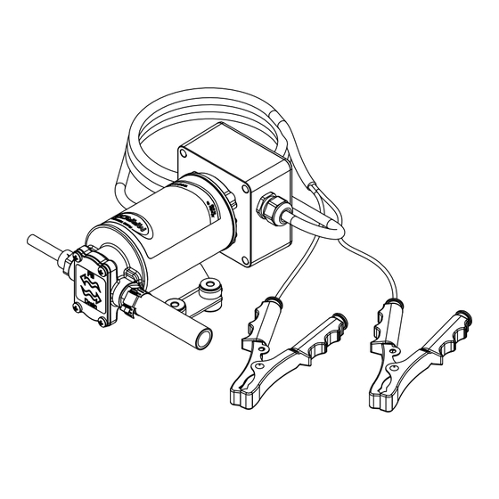
DESCRIZIONE DEL DISPOSITIVO Elettropompa autoadescante progettata per travaso di oli lubrificanti o di liquidi viscosi. Gli elementi pompanti sono costituiti da ingranaggi in bronzo che possono eventualmente girare a secco per brevi periodi. Completa di attacco rapido per tubo olio in aspirazione. DATI TECNICI Tab.1 IT CAVI *... -
Page 5: Condizioni Ambientali
CONDIZIONI AMBIENTALI ATTENZIONE: le temperature limite indicate si applicano ai componenti del dispositivo e devono essere rispettate per evitare possibili danneggiamenti o malfunzionamenti. Lo stoccaggio deve avvenire in luogo asciutto rispettando le medesime temperature. CICLO DI LAVORO La pompa può funzionare in servizio continuo alle seguenti condizioni: Ø... - Page 6 Per la corretta direzione del flusso del liquido come indicato dalla freccia sulla parte superiore, è necessario collegare il polo positivo (+) della batteria al filo rosso che esce dalla calotta della pompa e il polo negativo (-), al filo nero. I collegamenti elettrici vanno eseguiti utilizzando morsettiere e connessioni adeguate con accurato serraggio dei conduttori.
-
Page 7: Problemi E Soluzioni
PROBLEMI E SOLUZIONI COSA VERIFICARE SE LA POMPA NON PARTE O SI ARRESTA? Ø Verificare l'efficienza del generatore (presenza di tensione); Ø Verificare se il fusibile è interrotto; Ø Verificare la presenza di corpi estranei nel corpo della pompa. Per effettuare ciò verifica è... -
Page 8: Garanzia
Marco S.p.A. Questi costi saranno limitati ai costi di spedizione tra il magazzino di Marco S.p.A. e la sede del cliente. 7) Nessuna nota di credito o reso sarà emessa prima di un test eseguito dal controllo di qualità... -
Page 9: Product Description
PRODUCT DESCRIPTION Self-priming electric pump designed for lubricants and viscous fluids. The pumping elements are made up of bronze gear drives which can possibly even run dry for brief periods. Equipped with fast connector for oil suction pipe. TECHNICAL DETAILS Tab.1 EN CABLE * CODE... -
Page 10: Ambient Conditions
AMBIENT CONDITIONS TEMPERATURE: min.-10°C 14°F-max.60°C 140°F RELATIVE HUMIDITY: max. 90 % WARNING: the above indicated temperature ranges are applicable to all components of the pump and these limits must be respected in order to avoid any possible damage or malfunctioning. OPERATING CYCLE The pump can operate on a continuous cycle with the following conditions: Ø... - Page 11 To ensure the correct directional flow of the fluid as indicated by the arrow on the top plate, it is necessary to connect the positive pole (+) of the battery supply to the red wire on the motor end-cap and the negative pole (-) to the black wire. Electrical connections must be made using adequate terminal blocks and connectors ensuring a tight fitment of the electrical cables.
-
Page 12: Troubleshooting
TROUBLESHOOTING CHECK POINTS IF THE PUMP HAS STOPPED OR WILL NOT START Ø Check the effectiveness of the battery power supply (voltage activity); Ø Check if the fuse has blown; Ø Check for any foreign matter present in the pump body. To do this, disconnect the power supply and unscrew the four fixing screws, remove the front cover plate and inspect the chamber. -
Page 13: Environmental Disposal
5) The Warranty does not cover any related installation costs involved. 6) Transport costs are refundable only in the case where warranty has been duly accepted by Marco Spa and they will be limited to the actual shipment costs between Marco Spa warehouse and the client's delivery address. - Page 14 SEQUENZA DI MONTAGGIO / MOUNTING SEQUENCE Montare gli antivibranti (2) sulla pompa (1); Avvitare il portagomma (4), completo di o-ring (3), sul corpo pompa (1); Infilare la fascetta stringi tubo (5) sul tubo retinato (6); Calzare il tubo retinato (6) sul portagomma (4) ed avvitare la fascetta stringitubo (5); Avvitare l'innesto rapido (7) sul corpo pompa (1);...
- Page 15 SCHEDA DI MONTAGGIO / MOUNTING LAYOUT Pos. Q.tà Descrizione Description POMPA PUMP ANTIVIBRANTE ANTIVIBRATION MOUNT O-RING O-RING PORTAGOMMA TUBE OUTLET FASCETTA HOSE CLAMP TUBO RETINATO TUBE INNESTO RAPIDO QUICK FIT TUBO RILSAN Ø 8/6 L=1,2 m RILSAN TUBE Ø 8/6 L=1,2 m TUBO RILSAN Ø...
- Page 16 SCHEDA DI ASSEMBLAGGIO / EXPLODED VIEW Ricambio Pos. Q.tà Descrizione Description Spare Part CORPO POMPA PUMP BODY ANELLO DI TENUTA RUBBER LIP SEAL RONDELLA WASHER CUSCINETTO BALL BEARING O-RING O-RING TIRANTE CARCASSA PUMP FRAME INDOTTO ARMATURE CALOTTA PORTASPAZZOLE BRUSH HOLDER O-RING O-RING RONDELLA...
- Page 17 INGOMBRI / DIMENSIONS © S.p.A.
- Page 18 DIAGRAMMI / DIAGRAMS DIAGRAMMA PORTATA FLOW RATE DIAGRAM DIAGRAMMA ASSORBIMENTI AMPERE-DRAW DIAGRAM A (12V) A (24V) © S.p.A.
- Page 19 E.C. DECLARATION OF CONFORMITY Confermiamo che il prodotto: We confirm that the product: 164 931 15 - OCK1-E 12/24V Kit cambio olio / Oil change kit è conforme alla Direttiva 2004/108/CE (ex.89/336/CE) relativa alla compatibilità elettromagnetica. is in conformity with the Directive 2004/108/EC (ex.89/336/EC) relating to electromagnetic compatibility.
- Page 20 Questo documento e' proprieta' di Marco S.p.A la riproduzione e l'uso sono vietati. Tutti i diritti sono riservati. Per ulteriori informazioni vedere nostro sito internet - www.marco.it Marco S.p.A Via Mameli 10 - 25014 Castenedolo (Brescia) – Italia tel. +39 030 2134.1 / Fax +39 030 2134.300 Property of MARCO S.p.A reproduction prohibited.
Need help?
Do you have a question about the OCK1-E 12/24V and is the answer not in the manual?
Questions and answers