
Related Manuals for Marco 164 400 12-US - UP10 12V


Summary of Contents for Marco 164 400 12-US - UP10 12V
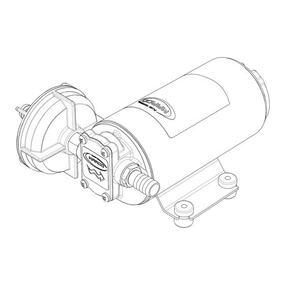
- Page 1 SELF-PRIMING ELECTRIC PUMP FOR TRANSFERRING VARIOUS LIQUIDS INSTRUCTIONS FOR USE 164 400 12-US - UP10 12V 164 400 13-US - UP10 24V © S.p.A.
-
Page 2: Product Description
PRODUCT DESCRIPTION Self-priming electric pump for the transfer of liquids of varied nature. The pumping elements are made up of bronze gears which can possibly even run dry for brief periods. Completely equipped with in-line filter on the inlet side. TECHNICAL DETAILS Tab.1 EN FUSE... -
Page 3: Ambient Conditions
AMBIENT CONDITIONS TEMPERATURE: min.-10°C 14°F-max.60°C 140°F RELATIVE HUMIDITY: max. 90 % WARNING: the above indicated temperature ranges are applicable to all components of the pump and these limits must be respected in order to avoid any possible damage or malfunctioning. OPERATING CYCLE The pump can operate on a continuous cycle with the following conditions: Ø... - Page 4 To ensure the correct directional flow of the fluid as indicated by the arrow on the top plate, it is necessary to connect the positive pole (+) of the battery supply to the red wire on the motor end-cap and the negative pole (-) to the black wire. Electrical connections must be made using adequate terminal blocks and connectors ensuring a tight fitment of the electrical cables.
-
Page 5: Troubleshooting
TROUBLESHOOTING CHECK POINTS IF THE PUMP HAS STOPPED OR WILL NOT START Ø Check the effectiveness of the battery power supply (voltage activity); Ø Check if the fuse has blown; Ø Check for any foreign matter present in the pump body. To do this, disconnect the power supply and unscrew the four fixing screws, remove the front cover plate and inspect the chamber. -
Page 6: Environmental Disposal
5) The Warranty does not cover any related installation costs involved. 6) Transport costs are refundable only in the case where warranty has been duly accepted by Marco Spa and they will be limited to the actual shipment costs between Marco Spa warehouse and the client's delivery address. - Page 7 EXPLODED VIEW P O S . Q .T Y D E S C R IP T IO N P UM P B ODY O-RING A RM A TURE P UM P FRA M E B RUSH HOLDER O-RING WA SHER IDLE GEA R DRIVING GEA R O-RING...
- Page 8 DIMENSIONS mm pollici / inches © S.p.A.
- Page 9 DIAGRAMS FLOW RATE DIAGRAM 14,5 43,5 72,5 101,5 116 AMPERE-DRAW DIAGRAM 14,5 43,5 72,5 101,5 116 © S.p.A.
- Page 10 E.C. DECLARATION OF CONFORMITY We confirm that the product: 164 400 12-US - UP10 12V Gear pump 164 400 13-US - UP10 24V Gear pump is in conformity with the Directive 2014/30/EU (ex. 2004/108/EC) relating to electromagnetic compatibility and with the Directive 2006/42/EC relating to the machines.
- Page 11 NOTES © S.p.A.
- Page 12 Property of MARCO S.p.A reproduction prohibited. All rights reserved. For further information visit our web site - www.marco.it Marco S.p.A Via Mameli 10 - 25014 Castenedolo (Brescia) – Italy tel. +39 030 2134.1 / Fax +39 030 2134.300...
Need help?
Do you have a question about the 164 400 12-US - UP10 12V and is the answer not in the manual?
Questions and answers