Advertisement
Control Unit for LED Light Units
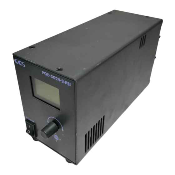
POD-5024-2-PEI
Instruction Guide
Thank you for purchasing a CCS product. To ensure
proper use of the product, please read this Instruction
Guide before use and keep it for your future reference.
This Control Unit is used to control the light intensity
of CCS LED Light Units. It is mainly used to control
LED Light Units that are used for machine vision or
industrial inspections.
Features
Both Overdrive and PWM Modes are supported.
Status confirmation and operation settings can be performed on the LCD.
External control can be performed with either Ethernet communications
or parallel communications.
You can register sets of parameters called scenes that consist of the
strobe times, light intensities, and other settings related to light control.
And then, you can apply the all of the parameters settings in any scene
to both channels at the same time.
1
Important Information for Equipment Safety
This product has been designed with full consideration of safety. However, incorrect usage of the product may result in fire, electric
shock, or other serious accidents. Observe the following precautions.
The following symbols are used in this Instruction Guide to indicate and
classify the relative importance of warnings and cautions.
Indicates that incorrect
Warning
u s a g e m a y r e s u l t i n
serious injury or death.
The following symbols indicate and classify the precautions in this
Instruction Guide.
DO NOT SUBJECT
DISASSEMBLY
DO NOT TOUCH
PROHIBITED
PROHIBITED
WITH WET HANDS
TO MOISTURE
These symbols indicate
prohibited actions.
Do not disassemble or modify
the Control Unit. Doing so may
result in fire or electric shock.
DISASSEMBLY
Make sure that the Control Unit
is f ree of water or any other
liquid. Exposure to water or other
DO NOT SUBJECT
liquid may result in fire or electric
TO MOISTURE
shock.
Do not touch the AC power cord
during thunderstorms. This may
result in electric shock.
PROHIBITED
I n di c ate s t h at i n c o r r e c t
Caution
usage may result in injury
or property damage.
MANDATORY
UNPLUG
ACTIONS
These symbols indicate
required actions.
Warning
Do not touch the plugs or switches
w it h wet hands. D oing so may
result in electric shock.
PROHIBITED
Before connecting or disconnecting
cables, make sure that the power
switch is turned OFF. Failure to do
so may results in fire, electric shock
or failure of the Light Units.
I f a n a b n o r m a l c o n d i t i o n , s u c h
a s s m o k i n g, a b n o r m a l h e at i n g,
abnormal odor, or noise, occurs, stop
using the Control Unit immediately,
turn OFF the power switch, and
unplug the AC power cord from the
wall socket. Continued use may
result in fire or electric shock.
PO D- 50 24 -2-
PE I
PO W ER
PU SH
INDEX
1. Important Information for
Equipment Safety
2. Names and Functions of Parts
3. Connections
4. Main Functions
5. Main Operation Flow
6. Operation Methods
7. Controlling Operation with
Ethernet Communications
8. Controlling Operation with
Parallel Communications
- Read Before Use -
Make sure that the AC power cord meets the following specifications.
100 to 120-V regions: SVT or SJT, AWG18, length: 3 m max., dielectric strength: 125 V min.
200 to 240-V regions: H05VV-F, AWG18, length: 3 m max., dielectric strength: 250 V min.
Do not connect any devices other
than CCS LED Light Units. Doing so
may cause the Control Unit to fail.
The warranty is void if the Control
Unit is connected to any other device.
Use a standard Extension Cable that is
manufactured by CCS. However, if the
cable is too long, the light intensity will
decrease due to voltage drop caused by
the DC resistance of the cable.
Do not place any objects within
50 mm from the air inlets and fan
exhaust outlet. Insufficient ventilation
may cause heat to accumulate inside
the Control Unit and result in fire.
Do not place the Control Unit in
direct sunlight or in a very humid
environment. Doing so may result in
fire due to internal temperature rise.
DO NOT TOUCH
Always place the Control Unit on a
WITH WET HANDS
stable and flat surface. Not doing so
may result in the Control Unit falling
or toppling, which may cause bodily
MANDATORY
injury or Control Unit malfunction.
ACTIONS
Do not bend a cable past its natural
bending radius or jam a cable into a narrow
space when wiring the Control Unit. Doing
so may cause Control Unit failure.
Do not wipe the Control Unit with
organic solvents, such as paint
thinner or benzene. Discoloration
UNPLUG
or deterioration of the Control Unit
surfaces may occur.
If there is dust or other foreign matter on the electrodes, turn OFF the power switch and
then use a dry cloth to remove the dust or foreign matter. Failure to do so may result in fire.
- 1 -
ETH ERN ET
L1
PAR ALL EL
L2
100 -24 0V~
50/ 60H z 65V
A
FG
TR IGG ER
9. Error Status
Page 1
10. Trigger Inputs
Page 2
11. Applying Scene Settings through
Page 2
Trigger Input Connector
Page 3
12. Optional Accessories
(Sold Separately)
Page 3
13. Main Specifications
Page 4
14. Dimensions
Page 6
Page 8
Caution
Plug the AC power cord directly
into t he wall s o c ket . Using a
power strip or connecting many
PROHIBITED
loads from one electrical socket
may cause fire or electric shock.
Do not bundle Control Unit cables
with high-voltage lines or power lines.
Doing so may cause the Control Unit
MANDATORY
ACTIONS
to malfunction. Allow leeway between
the cables when installing them.
Always ground the power cord. Not
doing so may cause Control Unit
failure due to static electricity, which
PROHIBITED
may destroy electrical components,
including those in the Light Units.
Use Light Units that are suitable
f o r t h e C o n t r o l U n i t r a t i n g s .
Exceeding the ratings may cause
PROHIBITED
Control Unit failure.
A lways hold onto the plug or
connector when disconnecting a
cable. Pulling on the cable may
PROHIBITED
damage the cable and result in
fire or electric shock.
Before moving the Control Unit,
disconnect all connecting cables.
Damaging the cables may result in
PROHIBITED
fire or electric shock.
When mounting the Control Unit in a
system rack or case, insertion depth into
the case of the Control Unit must be 4 mm.
PROHIBITED
If the inserted portion is too long, internal
components may be short-circuited.
Page 9
Page 10
Page 11
Page 11
Page 12
Page 12
MANDATORY
ACTIONS
MANDATORY
ACTIONS
MANDATORY
ACTIONS
MANDATORY
ACTIONS
MANDATORY
ACTIONS
MANDATORY
ACTIONS
MANDATORY
ACTIONS
MANDATORY
ACTIONS
MANDATORY
ACTIONS
Advertisement
Table of Contents

Related Manuals for CCS POD-5024-2-PEI


Summary of Contents for CCS POD-5024-2-PEI
- Page 1 Guide before use and keep it for your future reference. This Control Unit is used to control the light intensity PAR ALL EL of CCS LED Light Units. It is mainly used to control 100 -24 0V~ 50/ 60H z 65V...
-
Page 2: Names And Functions Of Parts
Names and Functions of Parts Front View Page 4 POD-5024-2-PEI Displays the light intensity, external control method, status of the Control Unit, and other information. Also displays the menus to set the Operating Knob Page 4 operation of the Control Unit. -
Page 3: Main Functions
Note: You must provide a cable with a length of 3 m max. Main Functions Control Methods The Light Units must support overdrive. Contact CCS to You can control the Control Unit with one of the following methods. Caution find out if your Light Units support overdrive. Incorrect usage of overdrive may result in failure of the Light Units. -
Page 4: Operation Methods
Operation Methods When the power to the Control Unit is turned ON, the Status Mode Display will appear on the LCD. Status Mode Display Manual Control Select the icon and then Set the CONTROL item on the COM Menu to MANUAL. Press in the press in the operating knob. - Page 5 Operation Methods (Continued) • COM Menu Display The COM Menu is used to specify the operation of the Control Unit. Note: Except for the TRIG item, the settings on the COM Menu will be saved after the power supply is turned OFF. Item Setting Default...
- Page 6 POD Control Unit An external device such as a PLC or image processing device transmits the send data to the Control Unit. The Control POD-5024-2-PEI Send data Unit processes the data and returns the results. The external device gets the receive data as the execution results.
- Page 7 Controlling Operation with Ethernet Communications (Continued) Receive Data Command word Header Channel specification Delimiter Normal send data Send data error 01: Invalid command error* < CR >< LF > Same value as for the send data. 03: Setting out of range error * This error occurs when the command in the send data is invalid, or when the CONTROL item on the COM Menu is set to MANUAL or PARALLEL and the Control Unit receives send data.
- Page 8 Controlling Operation with Parallel Communications You can set up the operation of the Control Unit and confirm the presence/absence of an error with control signal I/O through parallel communications connector. If you would like to control the operation with parallel communications, set the CONTROL item on the COM Menu to PARALLEL.
-
Page 9: Error Status
OUT ERROR An error was detected internally. The light outputs will stop. If detection of this error EEPROM ERROR, Internal error continues, contact CCS. TEMP ERROR, SYSTEM ERROR Confirmation Methods • LCD If any of the above errors is detected, the error name is displayed on the LCD. For information on error names, refer to LCD column in the above table. -
Page 10: Trigger Inputs
Trigger Inputs You can make a Light Unit flash by turning ON and OFF the photocoupler with a trigger signal input through the trigger input connector. Use pins 1, 2, and 10. Trigger inputs can be used for both manual control and external control. Trigger Input Connector Layout (Plug) Cable Signal... -
Page 11: Optional Accessories (Sold Separately)
10-pole connector: XG4M-1030-T (manufactured by OMRON) 19 20 20-pole connector: XG4M-2030-T (manufactured by OMRON) * Cables with enhanced noise resistance properties are also available. Contact your CCS 10-pole connector: XG4M-1030-T (manufactured by OMRON) sales representative for details. - 11 -... -
Page 12: Main Specifications
Contents of this Instruction Guide may be changed without prior notice. Illustrations used in this Instruction Guide may differ from actual products. CCS maintains the copyright on this Instruction Guide. Unauthorized transfer or reproduction is strictly prohibited. http://www.ccs-grp.com/ Copyright© 2019 CCS Inc. All Rights Reserved.
Need help?
Do you have a question about the POD-5024-2-PEI and is the answer not in the manual?
Questions and answers