Table of Contents
Advertisement
Quick Links
Control Unit for LED Light Units
PD3-10024-8-EI(A)
With Ethernet communications
Instruction Guide
Thank you for purchasing a CCS product.
To ensure proper use of the product,
please read this Instruction Guide before
use and keep it for your future reference.
This Control Unit is specifically designed to control the light intensity of
CCS LED Light Units. It is mainly used to control LED Light Units that
are used for machine vision and industrial inspections.
Features
Connect 24V DC Light Units and Spotlights. Use up to 8 channels.
The light intensity can be manually controlled with a switch on the front panel,
or externally controlled using Ethernet.
Use PWM control to control the 24V DC Light Unit output at a frequency of 125 kHz.
TCP/IP and UDP/IP Ethernet communications can be used for external control.
Use external trigger inputs to turn Light Units ON and OFF, or to flash the strobe
(for 24V DC Light Units only).
1
Important Information for Equipment Safety
This product has been designed with full consideration of safety. Incorrect
usage of the product may result in fire, electric shock, or other serious
damages. Observe the following precautions.
The following symbols are used in this instruction guide to indicate and classify the
relative importance of warnings and cautions.
Indicates that incorrect
WARNING
usage may result in
serious injury or death.
The following symbols in the instruction guide indicate and classify the precautions.
PROHIBITED
DISASSEMBLY
DO NOT TOUCH
PROHIBITED
WITH WET HANDS
These symbols indicate prohibited actions.
Do not disassemble or modify the Control
Unit. Doing so may result in fire or electric
shock.
DISASSEMBLY
Make sure that the Control Unit is free of
moisture or any liquid. Doing so may result
in fire or electric shock.
DO NOT SUBJECT
Do not touch the power cords during
lightning. This may result in electric shock.
Indicates that incorrect
Caution
usage may result in injury
or property damage.
MANDATORY
DO NOT SUBJECT
ACTIONS
TO MOISTURE
These symbols indicate required actions.
WARNING
Do not touch the plugs or switches with wet
hands. Doing so may result in electric shock.
PROHIBITED
Before connecting or disconnecting cables,
make sure that the power source is turned
OFF. Not doing so may result in fire or
electric shock.
TO MOISTURE
If an abnormal condition occurs, such as
fuming, heat, smell, or noise, stop using the
Control Unit immediately, turn OFF the power
source and unplug the power cord. Not doing
PROHIBITED
so may result in fire or electric shock.
INDEX
1. Important Information for Equipment Safety
2. Names and Functions of Parts
3. Installation
4. Connections
5. What You Can Achieve with This Control Unit
6. Light Unit Functions
7. Manual Control
8. Control with External Signals
Read before Use
Do not connect any Light Units other than
CCS LED Light Units. Doing so may cause
overcurrent and the device may overheat or
ignite.
Do not use user-made light cables.
Doing so may cause Control Unit failure.
Do not place the Control Unit in direct
sunlight or in a high-humidity environment.
Doing so may result in fire due to internal
temperature rise.
Always place the Control Unit on a stable and
flat location. Not doing so may result in the
Control Unit falling or toppling, which may
cause malfunction, accidents, or bodily injury.
UNPLUG
Do not drop the Control Unit or subject it to
impact. Doing so may cause Control Unit
failure.
Do not bend cables or jam them between
objects when wiring. Doing so may cause
Control Unit failure.
Do not intentionally short-circuit the positive
and negative output terminals.
DO NOT TOUCH
WITH WET HANDS
Do not wipe the Control Unit with volatiles
such as paint thinner or benzene.
MANDATORY
Discoloration or deterioration of the Control
ACTIONS
Unit surfaces may occur.
Use a dry cloth to remove dust or other
foreign matter from the electrodes. Failure to
do so may result in fire.
UNPLUG
1
1
9. Inputting an External Trigger
2
10. Errors
2
11. Optional Accessories
3
12. Troubleshooting
3
13. Main Specifications
4
14. Dimensions
5
6
7
Caution
Always use one of the following power cords.
100 to 120 V range: SVT or SJT, AWG18,
length: 3 m max., dielectric strength: 125 V min.
200 to 240 V range: H05VV-F, AWG18, length:
PROHIBITED
3 m max., dielectric strength: 250 V min.
Plug the power cord directly into a wall
socket. Using a power strip or connecting
many loads from one electrical outlet may
PROHIBITED
cause fire or electric shock.
Do not bundle Control Unit cables with
high-voltage lines or power lines.
Allow leeway when installing the cables.
PROHIBITED
Always ground the power cord. Not doing so
may cause Control Unit failure due to static
electricity destroying electrical components
including those in the Light Unit.
PROHIBITED
Use Light Units that are suitable for the
Control Unit ratings. Exceeding the ratings
may cause Control Unit failure.
PROHIBITED
Use a standard Extension Cable that is
manufactured by CCS. However, if the cable
is too long, the light intensity will decrease
due to voltage drop caused by the DC
PROHIBITED
resistance of the cable.
Do not disconnect the power cord or
disassemble the Control Unit during
operation. Pulling on the cable may damage
the cable and result in fire or electric shock.
PROHIBITED
Before moving the Control Unit, disconnect
all connection cables. Damaging the cables
may result in fire or electric shock.
PROHIBITED
When mounting the Control Units in system
racks or cases, do not insert the screws
more than 5 mm. Doing so may cause
short-circuits in internal components.
MANDATORY
ACTIONS
8
9
9
9
10
10
MANDATORY
ACTIONS
MANDATORY
ACTIONS
MANDATORY
ACTIONS
MANDATORY
ACTIONS
MANDATORY
ACTIONS
MANDATORY
ACTIONS
MANDATORY
ACTIONS
MANDATORY
ACTIONS
MANDATORY
ACTIONS
Advertisement
Table of Contents

Related Manuals for CCS PD3-10024-8-EI


Summary of Contents for CCS PD3-10024-8-EI
- Page 1 This Control Unit is specifically designed to control the light intensity of INDEX CCS LED Light Units. It is mainly used to control LED Light Units that are used for machine vision and industrial inspections. 1. Important Information for Equipment Safety 9.
-
Page 2: Setting Indicators
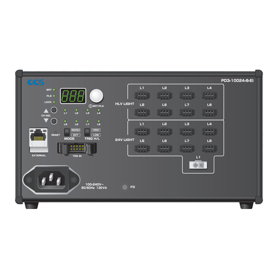
Names and Functions of Parts Setting Indicators Digital Display Setting Switch BRT lit: The light intensity can be set. Displays the setting of the Press: Switches between the light intensity setting and lighting mode setting. light intensity or the setting of PLS lit: The lighting mode can be set. -
Page 3: Application Guide
Connections Before connecting the Control Unit, make sure that the main WARNING power source is turned OFF. Making connections with the power turned ON may result in a fire or electric shock. Connect the LED Light Connect the LAN Cable (Provided by the user) Connect the connecting cable to the LED Light Unit to the output connector on the Control Unit. - Page 4 Light Unit Functions This Control Unit can be connected to Light Units and Spotlights with 24V DC inputs. Connect 24V DC Light Units to the 24V LIGHT connectors and Spotlights to HLV LIGHT connectors. The functions vary with the Light Units that are connected. Check the following table before using the Light Units. Output Connectors (HLV LIGHT) SMP-03V-BC×8 * Rated capacity per connector: 3.9 W max.
-
Page 5: Locking Settings
Manual Control Make sure that the main power source is turned ON. Precautions for Channel Selection when using Continuous Mode or ON/OFF Mode. * Set items , and Only channels with Light Units connected to them can be selected. If a Light Unit is removed Set items , and when using Strobe Mode. -
Page 6: Communications Specifications
Control with External Signals An external device such as a PLC or image processing device transmits the send data to the Control Unit. The Control Unit processes the data and returns the results. The external device gets the receive data as the execution results. Communications Specifications (*1) TCP/IP protocol or UDP/IP protocol (Switching operation is not required.), and Ethernet (Baud rate: 10 Mbps or 100 Mbps, automatically detected;... -
Page 7: Setting Procedures
Control with External Signals (Continued) *7) ON/OFF setting from Ethernet communications without regards to trigger logic switch, turned OFF at ‘0’ and ON at ‘1’. When operating Ethernet communications and trigger signal input at same time in ON/OFF mode. When Trigger logic switch is at HIGH: if either controls setting to OFF setting, Light unit will be turned OFF When Trigger logic switch is at LOW: if either controls setting to ON setting, Light unit will be turned ON *8) Checksum Example: Setting the Light Intensity of Channel 2 to 125... - Page 8 Inputting an External Trigger Input Signal and Photocoupler Lighting Delay Time The input signal from the external trigger input connector can be used to control the The lighting delay time for lights connected to 24V LIGHT connectors depends on the power photocoupler inside the Unit to turn the LED Light Units ON and OFF or to control consumption of the Light Unit.
-
Page 9: Optional Accessories (Sold Separately)
Please do not attempt to use or repair the product, since it abnormality. Is an appropriate Light Unit connected to the output is dangerous, but contact CCS Inc. connector? Check the Light Unit. Is the output connector the correct one for the connected Light Unit? Connect 24V DC Light Units to the 24V LIGHT connectors and Spotlights to HLV LIGHT connectors. -
Page 10: Main Specifications
Contents of this Instruction Guide may be changed without prior notice. Illustrations used in this Instruction Guide may differ from actual products. CCS maintains the copyright on this Instruction Guide. Unauthorized transfer or reproduction is strictly prohibited. http://www.ccs-grp.com/ Copyright© 2018 CCS Inc. All Rights Reserved.
Need help?
Do you have a question about the PD3-10024-8-EI and is the answer not in the manual?
Questions and answers