
Related Manuals for Sinclair SDV6-RPT


Summary of Contents for Sinclair SDV6-RPT
- Page 1 USER & INSTALLATION MANUAL SDV6-RPT C O M M E R C I A L A I R C O N D I T I O N E R S S D V 6...
-
Page 2: Table Of Contents
Contents Operating Precautions Instructions Main Parameters Product Overview Descriptions on Indicators Installation Precautions Instructions Package Contents Repeater Installation Power Cable Connection Communication Wire Connection... -
Page 3: Precautions
When the IDUs are powered separately and the number of IDUs to be connected is more than 10 or the communication distance is larger than 200, repeaters are required. Main Parameters Name SDV6-RPT 220-240V~ 50HZ Rated Voltage Operating environment temperature -5℃~43℃... -
Page 4: Product Overview
Product Overview Repeater A repeater is a connector working on the physical layer, with the following features: ● Signal repeater: re-transmits or forwards data signals to extend the network transmission distance. ● Power supply repeater: compensates the voltage drop caused by communication wire resistance to increase the bus voltage. -
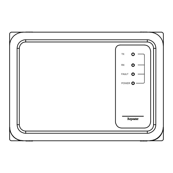
Page 5: Descriptions On Indicators
Descriptions on Indicators Communication indicator (yellow) Communication indicator (blue) Short circuit indicator (red) Power indicator (green) Repeater Normal Abnormal Indicator Remarks Communication indicator Blinking On/off Abnormal communication Communication indicator Blinking On/off Abnormal communication Short circuit of communication bus Short circuit indicator downstream the repeater Power indicator Abnormal power supply for the main board... -
Page 6: Installation Instructions
Installation Instructions Precautions ● To ensure correct installation, read the "Installation Instructions" section of this manual. ● All the warnings provided here are important for safety and must be followed. Warning ● Entrust the local distributor or local service agent to appoint a qualified technician to perform the installation. -
Page 7: Product List
Product List Please make sure if segments below are complete. Description Quantity Remarks SDV6-RPT repeater Used to increase bus voltage Providing instructions on Installation and Operation Manual repeater installation Philips head screw Used to fix the pedestal White plastic expansion pipe... -
Page 8: Repeater Installation
Repeater Installation Ⅰ. Push the cover hard on the screwdriver icon till snap fasteners of the cover seperate from the base, then open the cover. Install the power cables and communications wires properly according to the wiring diagram. Snap fastener Warning Make sure the power is off when operating. - Page 9 Ⅱ. Fix the repeater base on the wall or a proper location with a screwdriver. Four positions need to be fixed with screws. Location to accept a screw Ⅲ. Finally, close the upper cover and the bottom cap of the repeater and tighten them with two fixing screws.
-
Page 10: Power Cable Connection
Power Cable Connection Warning ● The power supply of the repeater cannot be cut off separately. It needs to be always powered on or switched on and off with the ODU power supply. ● Use round-type terminals with correct specifications to connect the power cable. The power cables must be a 2×1.0mm copper core cable. -
Page 11: Connection Of The Power Cables
Connection of the power cables Second wiring method: Let the power cable through the hole on the bottom side of the repeater to the CN1 power supply terminal (L N). Fix the wires with tie to avoid stress on the terminal block. Hole to pass wire Hole for tie... -
Page 12: Communication Wire Connection
Communication Wire Connection Warning Do not connect M1M2 with the IDU's PQ, D1D2 or X1X2 or any other different ● communication network. Otherwise, the circuit board will be damaged. If the total communication distance between IDU and ODU exceeds 200m or more ●... - Page 13 Connection of communication wires First wiring method: The communication wire should pass through the wire clamp on the right side of the repeater. The communication wire of the upstream IDU should be connected with CN3 (TO UP IDU) terminal block(M1 M2) while the communication wire of the downstream IDU connected with CN2 (TO DOWN IDU) terminal block(M1 M2).
- Page 14 Connection of communication wires Second wiring method: The communication wire should pass through the wire clamp on the bottom side of the repeater. The communication wire of the upstream IDU should be connected with CN3 (TO UP IDU) terminal block(M1 M2) while the communication wire of the downstream IDU connected with CN2 (TO DOWN IDU) terminal block (M1 M2).
-
Page 15: Connection Mode
Connection mode Master Communication wire Power cable CN23 Circuit breaker TO DOWN IDU Power supply for IDU ··· CN10 CN10 IDU 2-9# TO UP IDU repeater 1 IDU 1# IDU 10# TO DOWN IDU ··· CN10 CN10 IDU 12-19# TO UP IDU repeater 2 IDU 20# IDU 11#... - Page 16 Warning If the total communication distance does not exceed 200m and no more than 10 IDUs are configured, the units are powered by the master ODU and no repeaters are required. If the total communication distance exceeds 200m or more than 10 IDUs are configured, repeaters are required.
- Page 20 Please ask your local council where your nearest disposal station is located. P R O D U C E R R E P R E S E N T A T I V E SINCLAIR CORPORATION Ltd. SINCLAIR Global Group s.r.o. 16 Great Queen Street Purkynova 45 WC2B 5AH London...
Need help?
Do you have a question about the SDV6-RPT and is the answer not in the manual?
Questions and answers