
Related Manuals for Sinclair SDV6-MOD


Summary of Contents for Sinclair SDV6-MOD
- Page 1 USER AND INSTALLATION MANUAL SDV6-MOD C O M M E R C I A L A I R C O N D I T I O N E R S S D V 6...
-
Page 2: Table Of Contents
Contents Safety Precautions ......................2 Product Description .......................4 Function Codes for Commands ................5 1 Debugging ........................6 1.1 Checking the Communication Between the Gateway and Refrigerant System ...........................6 1.1.1 Opening Web Debugging Page .............6 1.1.2 Discrete input, Input Register ..............7 1.1.3 Determining Whether the Communication Is Normal......8 1.2 Modbus Interface Debugging................8 1.2.1 Configuring Modbus Gateway ..............9 1.2.2 Modbus/RTU .................... -
Page 3: Safety Precautions
Safety Precautions The Installation & Owner's Manual of this product describes how to properly handle the product, prevent personal injury and property losses, as well as how to use the product correctly and safely. Read the following carefully, make sure you understand the content (symbols and marks), and observe the precautions below. - Page 4 WARNING This unit must be installed by professional technicians. Users are not allowed to install the unit themselves; otherwise, personal injury or damage to the controller may occur. Other electrical wiring work must be carried out by a professional technician according to the circuit diagram.
-
Page 5: Product Description
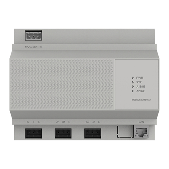
Product Description SDV6-MOD Gateway (this Gateway) provides standard Modbus services for VRF units.It is suitable for all SDV6 series units, that is, SDV6 ODUs and SDV6 IDUs. E A1 B1 E A2 B2 E Port Function 12V DC power supply... -
Page 6: Function Codes For Commands
Indicator Item Status Description The Gateway is powered off. Power supply Steady on The Gateway is powered on. Off/Steady X1Y1E No data transmitting X Y E communication status Blinking Data transmitting Off/Steady X2Y2E No data transmitting A1 B1 E communication status Blinking Data transmitting... -
Page 7: Debugging
1 Debugging According to the description above, connect the X Y E ports on the ODU to those on the access Gateway. (*1) A1 B1 E ports provide Modbus RTU protocol interfaces, and the LAN port provides Modus TCP protocol interfaces. The integrator can select the access mode based on the actual project requirements, and select the corresponding access mode for debugging. -
Page 8: Discrete Input, Input Register
1.1.2 Discrete Input and Input Register Click "DataView" to check the online information of the refrigerant system that the Gateway has obtained so far. -
Page 9: Determining Whether The Communication Is Normal
A pure number indicates an IDU, and the numeral indicates the IDU address. For example, IDU 0 "O#number" indicates an ODU, and the numeral indicates the ODU address. For example, ODU 0 Offline Online Selected RGB (210,212,214) RGB (225,243,216) RGBA (87,176,254,1) 0%, RGBA (64,144,245,1) 100% You can click an address to view the specific parameters of the device, and click "Discrete inputs"... -
Page 10: Configuring Modbus Gateway
1.2.1 Configuring Modbus Gateway On the "Settings" page, configure Modbus parameters. IP address of the Modbus Gateway address Network Settings Mask Subnet mask in the IP configuration Gateway Default gateway in the IP configuration Modbus interface configuration The first field indicates the baud rate. The default value is 9600. (Available Port values include 4800, 9600, 19200, and 38400.) Modbus... -
Page 11: Modbus/Rtu
1.2.2 Modbus/RTU Configuring Modbus/RTU Parameters Click "Connection" > "Connect" and configure Modbus Poll connection parameters: Choose "Serial Port" for "Connection" and "RTU" for "Mode". The serial port configuration needs to be consistent with the configuration in the Gateway "Modbus Settings". - Page 12 Click "Setup" > "Read/Write Enabled". If the 2 icon is not displayed, the auto sending function is cancelled. Click "Setup" > "Read/Write DefinitionⅢ" to set read/write configuration: Example: Read Discrete input Example: Read "On/Off status", "Fault status", and "Online status" of IDU 1. Refer to "2 Mapping Tables"...
- Page 13 Obtained Register address and Protocol address are as listed below. Name Register address Protocol address = Register address - 10001 ON/OFF 10009 Fault 10010 Online 10011 Modbus Poll adopts Protocol address. Set as follows: Modbus slave station address 1 (Slave ID: 1), command code 02 (Function: 02), start address 8 (Address: 8), read length 3 (Quantity: 3) Click "Read/Write Once".
- Page 14 The interpretation is listed below. Parameter name Register address Protocol address Value Definition ON/OFF 10009 Fault 10010 No fault Online Online 10011 Packets are listed below. Packet sent by Modbus Poll 01 02 00 08 00 03 B9 C9 Packet replied by Modbus Gateway 01 02 01 05 61 8B Example: Read Input Register Example: Read "Operating mode", "Operating fan speed", and "Set temperature"...
- Page 15 Click "Read/Write Once". The read values will be displayed in the area with a red box. The interpretation is listed below. Name Register address Protocol address Data Definition Operating mode 30033 Cool Medium fan speed Operating fan speed 30034 / Fan speed 4 Set temperature 30035 20・C...
- Page 16 01 04 00 20 00 03 B1 C1 01 04 06 00 02 00 04 00 C8 59 04 Packet replied by Modbus Gateway Example 1: Write Multiple Holding Register Example: Write "Set mode", "Set fan speed", and "Set temperature" of IDU 1. Refer to "2 Mapping Tables"...
- Page 17 Name Register address Protocol address = Register address - 40001 Set mode 40027 Set fan speed 40028 Set temperature 40029 Modbus Poll adopts Protocol address. Set as follows: Modbus slave station address 1 (Slave ID: 1), command code 16 (Function: 16), start address 26 (Address: 26), read length 3 (Quantity: 3) Click "OK", double-click the corresponding address (in the red box), and enter the desired control parameter in the displayed window (blue box), and click "OK"...
- Page 18 Set parameters: Name Register address Protocol address Data Definition Set mode 40027 66(0x42) Cooling upon startup Set fan speed 40028 03(0x03) Speed 3 Set temperature 40029 19(0x13) 19・C The above steps only configure the parameters to be written, and the command is not sent.
- Page 19 Packets are listed below. 01 10 00 1A 00 03 06 00 42 00 03 00 13 0E F7 Packet replied by Modbus Gateway 01 10 00 1A 00 03 A1 CF Example 2: Write Single Holding Register Example: Write "Set mode" of IDU 1. The IDU must support separate writing of a single parameter.
- Page 20 Click "OK", double-click the corresponding address (in the red box), and enter the desired control parameter in the displayed window (blue box), and click "OK" to close the window. Set parameters: Name Register address Protocol address Data Definition Set mode 40027 223 (0xDF) The above steps only configure the parameters to be written, and the command is not...
-
Page 21: Modbus/Tcp
Packets are listed below. 01 06 00 1A 00 DF E9 95 01 06 00 1A 00 DF E9 95 Packet replied by Modbus Gateway 1.2.3 Modbus/TCP For Modbus/TCP protocol interface debugging, set the IP address of the PC to be in the same network segment as that of the Modbus Gateway. - Page 22 Choose "TCP/IP" for "Connection" and enter the Gateway IP address in the "IP Address" field, such as 192.168.1.200: * Response Timeout and Delay Between Polls need to be adjusted based on the actual conditions of the project. For gateway debugging only, configurations in the screenshot above can be used.
- Page 23 Click "Setup" > "Read/Write DefinitionⅢ" to set read/write configuration: Example: Read Discrete input Example: Read "On/Off status", "Fault status", and "Online status" of IDU 1. Refer to "2 Mapping Tables" > "2.1 Discrete Input" > "2.1.1 IDU". n# IDU n*8+1+10000 On/Off status 0: off 1: on (The valid value...
- Page 24 Obtained Register address and Protocol address are as listed below. Name Register address Protocol address = Register address - 10001 On/Off status 10009 Fault status 10010 Online status 10011 Modbus Poll adopts Protocol address. Set as follows: Modbus slave station address 1 (Slave ID: 1), command code 02 (Function: 02), start address 8 (Address: 8), read length 3 (Quantity: 3) Click "Read/Write Once"..
- Page 25 The interpretation is listed below. Name Register address Protocol address Data Definition On/Off status 10009 Fault status 10010 No fault Online status 10011 Online Packets are listed below. 00 04 00 00 00 06 01 02 00 08 00 03 00 04 00 00 00 04 01 02 01 05 Packet replied by Modbus Gateway Example: Read Input Register...
- Page 26 Click "Read/Write Once". The read values will be displayed in the area with a red box. The interpretation is listed below. Name Register address Protocol address Data Definition Operating mode 30033 Cool Operating fan speed 30034 Medium fan speed/Fan speed 4 Set temperature 30035 20・C...
- Page 27 Packets are listed below. 00 87 00 00 00 06 01 04 00 20 00 03 00 87 00 00 00 09 01 04 06 00 02 00 04 00 C8 Packet replied by Modbus Gateway Example 1: Write Multiple Holding Register Example: Write "Set mode", "Set fan speed", and "Set temperature"...
- Page 28 Obtained Register address and Protocol address are as listed below. Name Register address Protocol address = Register address - 40001 Set mode 40027 Set fan speed 40028 Set temperature 40029 Modbus Poll adopts Protocol address. Set as follows: Modbus slave station address 1 (Slave ID: 1), command code 16 (Function: 16), start address 26 (Address: 26), read length 3 (Quantity: 3) Click "OK", double-click the corresponding address (in the red box), and enter the...
- Page 29 Set parameters: Name Register address Protocol address Data Definition Set mode 40027 66 (0x42) Cooling upon startup 03 (0x03) Set fan speed 40028 Speed 3 Set temperature 40029 19 (0x13) 19・C Click "Setup" > "Read/Write DefinitionⅢ": Click "Read/Write Once". Then, the command is sent: The above steps only configure the parameters to be written, and the command is not sent.
- Page 30 Packets are listed below. 00 89 00 00 00 0D 01 10 00 1A 00 03 06 00 42 00 03 00 13 00 89 00 00 00 06 01 10 00 1A 00 03 Packet replied by Modbus Gateway Example 2: Write Single Holding Register Example: Write "Set mode"...
- Page 31 Click "OK", double-click the corresponding address (in the red box), and enter the desired control parameter in the displayed window (blue box), and click "OK" to close the window.
- Page 32 Set parameters: Name Register address Protocol address Data Definition Set mode 40027 223 (0xDF) The above steps only configure the parameters to be written, and the command is not sent. Click "Setup" > "Read/Write DefinitionⅢ": Click "Read/Write Once". Then, the command is sent: Packets are listed below.
-
Page 33: Mapping Tables
2 Mapping Tables The conversion relationship between Register address and Protocol address is listed below. Protocol address (*4) Discrete input Protocol address = Register address - 10001 Input Register Protocol address = Register address - 30001 Holding Register Protocol address = Register address - 40001 (*4): By default, Modbus Poll uses Protocol address to read/write Modbus registers. - Page 34 3. General control parameters of IDUs include "Set mode", "Set temperature", "Set fan speed", "Cooling temperature in auto mode", "Heating temperature in auto mode", "Swing left/right", and "Swing up/down". Some models require that all the general control parameters are set at the same time. That is, command code 16 is used to set all the general control parameters at the same time.
-
Page 35: Discrete Input
2.1 Discrete Input 2.1.1 IDU Function code Register address Data length Name Definition 10001 1 bit On/Off 0: off 1: on 0: no fault 1: fault 10002 1 bit Fault 10003 1 bit Online 0: offline 1: online 10004 1 bit 0#IDU 10005 1 bit... -
Page 36: Input Register
Function code Definition Register address Data length Name 11009 On/Off 0: off 1: on 0: no fault 1: fault 11010 1 bit Fault 11011 1 bit Online 0: offline 1: online 0: off 1: on 11012 1 bit Fan 1 on/off 1#ODU 11013 1 bit... - Page 37 Function Register Data Name Definition code address length Heating temperature 30005 2 Bytes Actual temperature (・C) ¨ 10 in auto mode 30006 2 Bytes Indoor ambient Actual temperature (・C) ¨ 10 temperature Low byte of error code+Bit 0 of the high byte of the error code No fault 1~20...
- Page 38 Function Register Data Name Definition code address length Fan speed unlocked 7-fan-speed IDU 1-7: speed 1 to speed 7 locked 3-fan-speed IDU 30016 2 Bytes Fan speed lock 1, 2: low fan speed locked 3, 4: medium fan speed locked 5, 6, 7: high fan speed locked Auto fan speed locked 30017...
- Page 39 Function Register Data Name Definition code address length 0#IDU 30030 2 Bytes Reserved Reserved 30031 2 Bytes Reserved Reserved 30032 2 Bytes Reserved Reserved Ⅲ Ⅲ Ⅲ Ⅲ Ⅲ Ⅲ Bit7 Auto mode 1: yes, 0: no Actual mode 0: Shutdown 30001+n*32 2 Bytes Operating mode 1: Fan 2: Cooling...
- Page 40 Function Register Data Name Definition code address length 30008+n*32 2 Bytes Swing left/right 1-5: swing angle 1-5, 14: auto swing 30009+n*32 2 Bytes Swing up/down 1-5: swing angle 1-5, 14: auto swing 30010+n*32 2 Bytes Upper limit of Actual temperature (・C) ¨ 10 cooling temperature 30011+n*32 2 Bytes Lower limit of Actual temperature (・C) ¨...
-
Page 41: Odu
Function Register Data Name Definition code address length 0霁1st Generation IDU 12霁Inverter Split AC 1霁4-Way Cassette 13霁Heat Recovery 2霁Wall-mounted Ventilator 3霁Medium Static Pressure 14霁1-Way Cassette Duct 15霁2-Way Cassette 4霁Low Static Pressure Duct 16霁console 30023+n*32 2 Bytes IDU model 5霁Air Handling Unit 17霁High Temperature 6霁High Static Pressure Duct Hydro Module... - Page 42 Function Register Data Name Definition code address length 34006 2 Bytes Frequency of Speed of compressor 2 compressor 2 34007 2 Bytes Discharge temperature Discharge temperature of compressor 1 of compressor 1 34008 2 Bytes Discharge temperature Discharge temperature of compressor 2 of compressor 2 34009 2 Bytes...
- Page 43 Function Register Data Name Definition code address length 34002+20*n 2 Bytes Fan 1 Speed of fan 1 34003+20*n 2 Bytes Fan 2 Speed of fan 2 34004+20*n 2 Bytes Outdoor ambient Actual temperature (・C) ¨ 10 temperature 34005+20*n 2 Bytes Frequency of Speed of compressor 1 compressor 1...
-
Page 44: By Idu/Odu Parameter Type (Continuous Addresses)
2.2.3 By IDU/ODU Parameter Type (Continuous Addresses) Function Register Data Name Definition code address length 36001 2 Bytes IDU 0 Bit7 Auto mode 1: yes, 0: no 36002 2 Bytes IDU 1 Actual mode 36003 2 Bytes IDU 2 0: Shutdown Ⅲ... - Page 45 Function Register Data Name Definition code address length Bit 00: operating status of IDU 16, 1: on, 0: off Bit 01: operating status of IDU 17, 1: on, 0: off 36258 2 Bytes IDUs 16-31 Bit 15: operating status of IDU 31, 1: on, 0: off Bit 00: operating status of IDU 32, 1: on, 0: off...
- Page 46 Function Register Data Name Definition code address length Bit 00: online status of IDU 48, 1: online, 0: offline Bit 01: online status of IDU 49, 1: online, online 0: offline 36264 2 Bytes IDUs 48-63 status Bit 15: online status of IDU 63, 1: online, 0: offline Bit 00: fault status of IDU 00, 1: yes, 0: no Bit 01: fault status of IDU 01, 1: yes, 0: no...
- Page 47 Function Register Data Name Definition code address length Bit 00: operating status of ODU 16 (system 04), 1: yes, 0: no Bit 01: operating status of ODU 17 (system 04), 1: yes, 0: no Bit 12: operating status of ODU 28 operating (system 07), 1: yes, 0: no 36270...
-
Page 48: Holding Register
Function Register Data Name Definition code address length Bit 00: online status of ODU 00 (system 00), 1: yes, 0: no Bit 01: online status of ODU 01 (system 00), 1: yes, 0: no Bit 12: online status of ODU 12 online (system 03), 1: yes, 0: no 36273... -
Page 49: Idu Control Register-1
2.3.2 IDU Control Register 1 Function Register Data Name Definition code address length 0xFF: unchanged 0x9F: off 0xDF: on Start up and specify the operating mode: Auto mode, valid when the Bit7 value is 1 06/16 40002 2 Bytes Set mode Fixed to 1 Bit6 Fixed to 0... - Page 50 Function Register Data Name Definition code address length 0xFF: unchanged 0.5・C, 1: yes, 0: no Bit7 The setting range of 1-100 Bit0-Bit6 means 1・C to 100・C. Cooling temperature 06/16 40005 2 Bytes Examples: in auto mode 0x91: The cooling temperature in auto mode is 17.5・C.
- Page 51 Function Register Data Name Definition code address length 0xFF: unchanged 0.5・C, 1: yes, 0: no Bit7 The setting range of 1-100 Bit0-Bit6 means 1・C to 100・C. Lower limit of 06/16 40010 2 Bytes Examples: heating temperature 0x91: The lower limit of the heating temperature is 17.5・C.
- Page 52 Function Register Data Name Definition code address length 0x0F: unchanged 0: unlocked 06/16 40014 2 Bytes On/Off lock 1: on locked 2: off locked Unchanged 0x0F Unlock Bit0~Bit4 For a 7-fan-speed IDU, values 1-7 indicate fan speeds 1 to 7, respectively. For a 3-fan-speed IDU, 06/16 40015...
- Page 53 Function Register Data Name Definition code address length 0xFF: unchanged 0x9F: off 0xDF: on Start up and specify the operating mode: Bit7 Auto mode, valid when the 06/16 40002+n*25 2 Bytes Set mode value is 1 Bit6 Fixed to 1 Bit5 Bit0~Bit4 Fixed to 0...
- Page 54 Function Register Data Name Definition code address length 0xFF: unchanged 0.5・C, 1: yes, 0: no Bit7 The setting range of 1-100 Bit0-Bit6 means 1・C to 100・C. Cooling temperature Examples: 06/16 40005+n*25 2 Bytes in auto mode 0x91: The cooling temperature in auto mode is 17.5・C.
- Page 55 Function Register Data Name Definition code address length 0xFF: unchanged 0.5・C, 1: yes, 0: no Bit7 The setting range of 1-100 Bit0-Bit6 means 1・C to 100・C. Lower limit of Examples: 06/16 40010+n*25 2 Bytes heating temperature 0x91: The lower limit of the heating temperature is 17.5・C.
- Page 56 Function Register Data Name Definition code address length 0x0F: unchanged 0: unlocked 06/16 40014+n*25 2 Bytes On/Off lock 1: on locked 2: off locked Unchanged 0x0F Unlock Bit0~Bit4 For a 7-fan-speed IDU, values 1-7 indicate fan speeds 1 to 7, respectively. For a 3-fan-speed IDU, 06/16 40015+n*25 2 Bytes...
-
Page 57: Idu Control Register-2
2.3.3 IDU Control Register 2 Use registers 41602-41605 to select the desired IDU and use registers 41606-41622 to set specific group control parameters. Function Register Data Name Definition code address length Control IDUs 0-15 Bit 0: IDU 0. 1: selected, 0: unselected Selection of IDUs 06/16 41602... - Page 58 Function Register Data Name Definition code address length 0xFF: unchanged Auto fan speed 1: yes, 0: no Bit7 Bit0-Bit6 For a 7-fan-speed IDU, values 1-7 indicate fan speeds 1 to 7, respectively. For a 3-fan-speed IDU, values 1 and 2 indicate low 06/16 41607 2 Bytes...
- Page 59 Function Register Data Name Definition code address length 0xFF: unchanged 41611 2 Bytes Swing left/right 1-5: angle 1 to angle 5 06/16 14: auto swing 0xFF: unchanged 41612 2 Bytes Swing up/down 1-5: angle 1 to angle 5 06/16 14: auto swing 0xFF: unchanged 0.5・C, 1: yes, 0: no Bit7...
- Page 60 Function Register Data Name Definition code address length 0xFF: unchanged 0.5・C, 1: yes, 0: no Bit7 The setting range of 1-100 Bit0-Bit6 means 1・C to 100・C. Lower limit of 06/16 41616 2 Bytes Examples: cooling temperature 0x91: The lower limit of the cooling temperature is 17.5・C.
- Page 61 Function Register Data Name Definition code address length 0x03: unchanged Remote controller Group 06/16 41621 2 Bytes 0: unlocked lock control 1: locked of any 0x03: unchanged 06/16 41622 2 Bytes Wired controller lock 0: unlocked 1: locked 06/16 41623 2 Bytes Reserved Reserved...
-
Page 62: Web Function
3 Web Functions The Gateway is embedded with a web server, which can be used to upgrade and configure the Gateway. The default IP address of the Gateway is 192.168.1.200. In the address bar of Chrome browser, enter "http://Gateway IP address" to open the web page of the Gateway. 1. -
Page 63: System Settings
3.1 System Settings Web function list Device Version Version of the Modbus Gateway Infos IP address of the Modbus Gateway address Network Settings Mask Subnet mask in the IP configuration Gateway Default gateway in the IP configuration Modbus interface configuration The first field indicates the baud rate. -
Page 64: Dataview
3.2 DataView A pure number indicates an IDU, and the numeral indicates the IDU address. For example, IDU 0 "O#number" indicates an ODU, and the numeral indicates the ODU address. For example, ODU 0 Offline Online Selected RGB(210,212,214) RGB(210,212,214) RGBA(87,176,254,1) 0%, RGBA(64,144,245,1) 100%) You can click an address to view the specific parameters of the device, and click "Discrete inputs"... -
Page 65: Firmware Upgrade
3.3 Firmware Upgrade Click "Select the file to upload", select the desired firmware in the displayed window, and click "Upload". * Only professionals can use this function. Otherwise, the Modbus Gateway may be damaged and cannot be used. -
Page 66: Restoring Factory Settings
4 Restoring Factory Settings Restoring Factory Function Settings When the factory configuration is restored, the Gateway IP address and other parameters are set to factory setting values. Steps: 1. Cut off the Gateway power supply, open the Gateway shell, press and hold SW1 and turn on the power of the Gateway;... -
Page 67: Installation
Installation 1 Product Introduction E A1 B1 E A2 B2 E 2 Product Dimensions Unit: mm 51.5 74.5... -
Page 68: Installation Accessories
3 Installation Accessories Please confirm that you have all the following parts. Name Quantity Remarks Self-tapping screw ST4*20 For installing the controller onto the wall Plastic expansion pipe 3-pin black terminal For communication 3-pin gray terminal For connecting the power supply Module:AP24S1200WP-XS1 Input:100-240V~50/60Hz 0.8A Power adaptor... - Page 69 2. Mounting the Device on the Wall Pull open the handle buckle Philips head screw ST4*20 Plastic expansion (This fixing screw is pre-inserted into the pipe wall and the distance from the highest position of the nut to the wall is 5.5 mm) Philips head screw ST4*20 6 mm drill bit, with a minimum drill depth of...
- Page 72 United Kingdom www.sinclair-world.com This product was manufactured in China (Made in China). R E P R E S E N T A T I V E SINCLAIR Global Group s.r.o. Purkynova 45 612 00 Brno Czech Republic T E C H N I C A L S U P P O R T SINCLAIR Global Group s.r.o.
Need help?
Do you have a question about the SDV6-MOD and is the answer not in the manual?
Questions and answers