
Related Manuals for Kistler 5073B Series


Summary of Contents for Kistler 5073B Series
- Page 1 Instruction Manual Industrial Charge Amplifier for Multi-purpose with Ethernet Type 5073B…...
- Page 2 Information in this instruction manual is subject to change any time without notice. Kistler reserves the right to improve and modify its products in the course of technical advancement, without any obligation to inform any persons or organizations of such changes.
-
Page 3: Table Of Contents
Type 5073B… Content Introduction ..........................4 Safety and Liability ........................6 General ..........................6 Setting up and using your Product ..................6 Electromagnetic Compatibility (EMC) ................. 7 Warnings and their Relevance .................... 8 Transportation and Storage ....................8 Product use ......................... 8 Software Upgrades and Updates .................. - Page 4 Content Service and Maintenance ......................49 Cleaning and storage ......................49 Services ..........................49 Inspection for visible Damage .................... 50 Repair ..........................50 Drift............................. 50 Technical Data ..........................53 General ..........................53 Certification Information ......................54 CE (Europe) ........................54 UKCA (UK) .........................
-
Page 5: Introduction
It will help you with the installation, maintenance, and use of this product. To the extent permitted by law Kistler does not accept any liability if this instruction manual is not followed. Kistler offers a wide range of products for use in measuring technology. - Page 6 Our product and application brochures will provide you with an overview of our product range. Detailed data sheets are available for almost all products. If you need additional help beyond what can be found either online or in this manual, please contact Kistler's extensive support organization. Page 5...
-
Page 7: Safety And Liability
2. The specifically applicable instruction manual for the purchased product Instruction manuals for each product are available on the Kistler website and can be accessed via the type number www.kistler.com. Paper instruction manuals can also be requested from Kistler's customer service or the responsible Kistler sales department. -
Page 8: Electromagnetic Compatibility (Emc)
Center or its distributor. The delivery scope must be checked before starting to set up the product. If a part is missing, the responsible Kistler Sales Center or its distributor must be notified. If the product has visible signs of damage, no longer... -
Page 9: Warnings And Their Relevance
Type 5073B… 2.4 Warnings and their Relevance Disregard of the following precautions can lead to malfunctions damage system components, environment or people (see table below). Disregard may have consequence Mechanical defects with unpredictable consequence (might endanger material or people) Indicates a caution or warning notice Indicates a tip or important information 2.5 Transportation and Storage All the following safety precautions must be taken if the... -
Page 10: Software Upgrades And Updates
Kistler Instrument sales office for return instructions. Please contact your Kistler Sales Center if you have any questions about disposal. Contact addresses and further information can be found www.kistler.com... -
Page 11: Fundamentals
Only use unadulterated cleaning agents, for example 1003 cleaning spray from Kistler or white spirits, on a clean, lint-free paper towel. High insulation sensor cables... -
Page 12: The Industrial Charge Amplifier
Polarity Kistler defines polarity in such a way that an increase in compressive force in a force sensor produces a negative charge. The charge amplifier inverts the sensor signal and, in this case, generates a positive output voltage. - Page 13 Type 5073B… The following approximate formula is adequate for calculating the voltage signal in most cases: = -Q / C At the end of each measuring cycle the negative feedback capacitor is discharged by means of the Reset command and the output signal is set to zero in order to prevent zero drift during measurement.
-
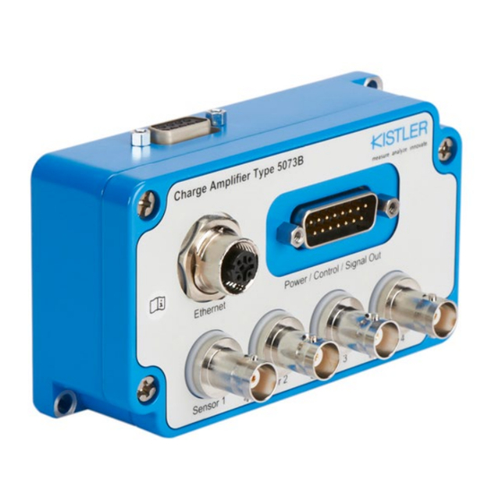
Page 14: Device Description
Device Description 4. Device Description 4.1 Purpose of the 5073B charge amplifier The industrial charge amplifier for multi-purpose (ICAM-B) can be used wherever mechanical quantities are measured with piezoelectric sensors. Piezoelectric sensors produce an electric charge which varies in direct proportion to the load acting on the sensor. -
Page 15: Block Diagram
Type 5073B… 4.2 Block diagram Page 14... -
Page 16: Dimensions
Device Description 4.3 Dimensions Page 15... -
Page 17: Led Status Indicator
Type 5073B… 4.4 LED status indicator Page 16... -
Page 18: Ordering Information
Device Description 4.5 Ordering information 4.6 Included accessories Quick start guide 55274765 Protective cap IP54 for sensor input 18000844 BNC neg. Protective cap IP54 for sensor input 18000850 TNC neg. Protective cap IP54 for sensor input 18000855 KIAG 10-32 neg. Protective cap for M12 socket (IP67) 55160137 Protective cap for D-Sub 15-pole... -
Page 19: Accessories (Optional)
55273284 Null modem mini adapter, 1489 D-Sub 9-pole pos. – D-Sub 9-pole neg. It is only allowed to use Kistler approved Accessories. Please note that product approval, certifications and warranty apply only to the device in combination with explicit Kistler approved accessories. -
Page 20: Commissioning
Type 1003 cleaning spray or white spirit. Connect the cable to the sensor. We recommend using high-insulation, low-noise cables from Kistler. These are tested specifically for high insulation resistance, low noise and low unwanted (triboelectric) charge produced by friction. If the cable is moved during operation, it should not be suspended over spans exceeding 30 ... -
Page 21: Network Connection
Type 5073B… 5.1.2 Network connection The Ethernet interface enables remote access, remote configuration and monitoring, firmware update, integration with control systems, data streaming and a web-based user interface. Connector Function M12 4-pole neg. D- coded Shield 5.1.3 Power/Control/Signal out The D-Sub 15-pole connector is used to connect the supply voltage. -
Page 22: Optional Rs232
Commissioning 5.1.4 Optional RS232 The optional RS-232C interface was kept for reverse compatibility to 5073A. This interface can be used to integrate the 5073B… into control systems, or to configure the device via ManuWare software in 5073A compatibility mode. Connector Function D-Sub 9 pole neg. - Page 23 Type 5073B… For the connections that are galvanically insulated, there shall defined connection of the measuring chain to a ground level. Potential differences from Sensor to Amplifier Mounting Area On single channel 5073B1… device, either sensor or amplifier shall be connected to ground, in order to not have a floating measurement system.
-
Page 24: Device Configuration And Operation
Kistler website www.kistler.com. Start the «Network Setup Wizard» tool that finds all Kistler network devices. Then, click on «Find Devices…» and wait until Kistler network devices are displayed. It may take up to 30 seconds until the devices are displayed. -
Page 25: Home Screen In The Web Ui
Type 5073B… 6.2 Home screen in the web UI Upon accessing the web UI of the 5073B…, you will be directed to the Home screen of the user interface. The Home screen contains the following elements: A) Status bar B) Navigation pane C) Y-t graphs D) Sensor portlets Each of the elements are explained in detail in the... -
Page 26: Status Bar
Device configuration and operation 6.2.1 Status bar Minimizes and re-opens the navigation pane User defined device name Switch to change the amplifier’s operation mode from Reset to Measure and vice versa. Blue shows the active status. If this switch is used, the Measure or Reset status will be applied to all channels. Makes your device blink yellow with device LED. -
Page 27: Navigation Pane
Type 5073B… 6.2.2 Navigation pane Navigates to the «home screen», an overview page. Shows important channel and device configurations and some measurement values. Navigates to the sensor configuration page. Navigates to the configuration page of the virtual channels which allow calculations with the sensor signals in real time. -
Page 28: Graphs
Device configuration and operation 6.2.3 Graphs The number of graphs to be displayed on the Home screen can be selected from the drop down. Graphs settings such as channels to be displayed on the graph and scale of the axes can be adjusted by clicking on this icon. -
Page 29: Sensor Portlets
Type 5073B… 6.2.4 Sensor portlets The sensor portlets show the most important status information, settings, and measurement values of the input channels of the 5073B. Clicking on a portlet navigates to the sensor configuration page for the respective channel. The channel number, the entered channel name and serial number are shown. -
Page 30: Sensor Configuration Page
Device configuration and operation This shows the minimum signal value before Reset. This shows the maximum signal value before Reset. This shows the rms (root mean square) of the signal value before Reset. This shows the live value of the signal. 6.3 Sensor configuration page Page 29... -
Page 31: Channel Selection
Type 5073B… A) Channel selection The sensor portlets in the channel selection section have two functions: Show the most important information of the channel (configuration & values). The portlets are identical to the sensor portlets on the home screen. Selection of the channel(s) which shall be configured in the ... -
Page 32: Virtual Channel Configuration Page
Device configuration and operation 6.4 Virtual Channel configuration page Virtual channels can be used for real-time calculations using one or more sensor channels. In general, the measuring values coming from the sensor channels are taken as “pure numbers” only without any unit. After the calculation stage, the values are receiving again a physical unit and the respective range has to be specified like on a sensor channel. - Page 33 Type 5073B… B) Configuration section Here are the parameters that can be set by the user. Enabled: activates the virtual channel Name: enter a virtual channel name of your choice. User Range: enter the range you expect from your virtual channel signal. Output Unit: unit can be entered by typing the desired unit in the field.
-
Page 34: Analog Output Configuration Page
Device configuration and operation 6.5 Analog output configuration page Page 33... - Page 35 Type 5073B… A) Analog output selection The analog output portlets have two functions: Show the most important information of the analog output Selection of the analog output(s) which shall be configured in the configuration section B) B) Analog output configuration section Here are the parameters that can be set by the user.
-
Page 36: Digital Input/Output Configuration Page
Device configuration and operation Output nominal: the output range can be adjusted to a value other than ±10 V between -10V and +10V. The graph here illustrates the scaling when offset is 2V and nominal output is 5V. Scale: The scale is then calculated using the offset and nominal output values defined by the user. - Page 37 Type 5073B… The 15-pole D-sub connector features 5 pins that can function as digital input/output. Pin 8 is exclusively designated for digital input, whereas pins 12 to 15 offer the flexibility to be configured as either input or output. A) Digital IO selection The digital input/output portlets have two functions: Show the most important information of the digital IO ...
-
Page 38: Connections Configuration Page
Device configuration and operation 6.7 Connections configuration page Page 37... - Page 39 Type 5073B… The connections configuration page is only available if licensed IIoT feature package is purchased. This package includes MQTT for data streaming and OPC UA for parametrization. A) Protocol selection The connection portlets have two functions: Show the most important information of each ...
- Page 40 Device configuration and operation C) MQTT Data Set selection The data to be streamed can be defined by selecting the channel number and the signal mode for the corresponding channel. Page 39...
-
Page 41: Evaluation Configuration Page
Type 5073B… D) OPC UA configuration OPC UA can be enabled using the switch in the configuration section. The OPC UA certificate can be renewed in the Renew section. 6.8 Evaluation configuration page Page 40... - Page 42 Device configuration and operation Evaluation might be used to define process limits. This may help customers using different sensor assemblies, or assemblies in various processes, to control specific process levels according to assembly limits or process limits. A) Evaluation selection The evaluations portlets have two functions: Show the most important information of the ...
-
Page 43: Device Configuration Page
Type 5073B… Window The switching state changes when the current measurement value passes the Setpoint SP1 and Setpoint SP2. This change occurs with rising or falling measurement values. If hysteresis is defined for SP1 and SP2, the switching behavior shall observe the hysteresis as shown. This behavior shows symmetrical hysteresis in respect to SP1 and SP2. - Page 44 Device configuration and operation In this section, device related information such as device type, serial number, device name, network settings, connector guide and date/time settings are shown and can be adjusted. A) Device In this section, device name and device description can be changed.
-
Page 45: Notification Page
Type 5073B… 6.10 Notification page All the error messages and notifications are store in this section. The notifications then can be cleared or archived by the user. 6.11 Maintenance page Page 44... - Page 46 Firmware update can be done by uploading the FW package available at the Kistler website (www.kistler.com). Once the file is selected, upload button has to be clicked. Once uploading the file is completed, confirm button has to be pressed.
-
Page 47: Software Licensing
MQTT for data streaming, which makes the amplifier suitable for a variety of applications across industries by providing efficient communication. The license can be purchased either from the Kistler web shop or from the sales representatives in your country. To enable the license, the software licensing in the Maintenance section can be opened. - Page 48 Device configuration and operation By clicking on Manage Licenses, a window will be opened, where the new license can be activated. Certificate The device 5073B… creates a self-signed certificate upon booting up the device. A self-signed certificate is a type of digital certificate that is signed by its own creator rather than a trusted certificate authority (CA).
- Page 49 Type 5073B… License agreement and some links to customer services and support are available in the maintenance section as well. User Management Upon initial setup or following a factory reset, a prompt will appear to establish a username and password. Users have the option to either create a username and password or proceed without setting up a user account.
-
Page 50: Service And Maintenance
Use only a clean, soft, lint-free cloth for cleaning. If necessary, moisten the cloth with water. Do not use other liquids as they may attack the housing. For cleaning of the connectors use the Kistler cleaning spray Type 1003. 7.2 Services... -
Page 51: Inspection For Visible Damage
If a major repair is necessary, you will receive a • cost estimate • Kistler will endeavor to repair your device in a short time and at minimal cost and send it to you in as-new condition 7.5 Drift It is recommended to have the charge amplifier... - Page 52 Please make sure, that the internal time constant functionality is not activated, since this would result in such behavior. To rectify the defect, return the charge amplifier to the responsible Kistler sales center/distributor for repair. Cause 2 The signal at the output drifts linearly in the positive or negative direction.
- Page 53 Type 5073B… Note Cause 3 is readily diagnosed by removing the sensor and sensor cable and connecting a charge calibrator for testing. Page 52...
-
Page 54: Technical Data
Technical Data 8. Technical Data This chapter only contains safety-relevant technical data. For all other technical data, please refer to the data sheet on our website www.kistler.com. 8.1 General Environment Indoor/outdoor Altitude <2000 Operating temperature range °C -20 … 65 Storage temperature °C... -
Page 55: Certification Information
Type 5073B… 9. Certification Information 9.1 CE (Europe) Hereby, Kistler Instrumente AG declares that the charge amplifier Type 5073B is in compliance with Directive 2014/30/EU. 9.2 UKCA (UK) Hereby, Kistler Instrumente AG declares that the charge amplifier Type 5073B is in compliance with Directive UK SI 2017 No. -
Page 56: Ic (Canada)
Certification Information 9.4 IC (Canada) Canada Compliance Statement: This device contains license-exempt transmitter(s)/receiver(s) that comply with Innovation, Science and Economic Development Canada’s license-exempt RSS(s). Operation is subject to the following two conditions: 1. This device may not cause interference. 2. This device must accept any interference, including interference that may cause undesired operation of the device.
Need help?
Do you have a question about the 5073B Series and is the answer not in the manual?
Questions and answers