
Subscribe to Our Youtube Channel
Related Manuals for Kistler 5159A Series


Summary of Contents for Kistler 5159A Series
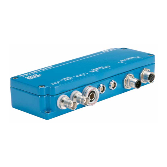
- Page 1 Instruction Manual Charge and thermocouple amplifier Type 5159A... 5159A_002-890e-12.19...
- Page 3 © 2019 Kistler Group. Products of the Kistler Group are pro- tected by various intellectual property rights. For more infor- mation, visit: www.kistler.com. The Kistler Group includes Kistler Holding AG and its subsidiaries in Europe, Asia, the Americas and Australia.
-
Page 4: Table Of Contents
Charge and thermocouple amplifier, Type 5159A... Table of contents Introduction ..........................3 Safety information .......................3 Electromagnetic compatibility (EMC) ..................4 Warnings ..........................4 Information on disposal of electronic equipment ..............5 Software upgrades and updates ..................5 Basic information ........................6 2.1 Charge amplifier .........................7 2.1.1 Analog charge amplifier..................7 2.1.2 Digital charge amplifier as per EUROMAP 75 (VARAN or EtherCAT) ....8... -
Page 5: Introduction
Introduction 1. Introduction Thank you for opting for a Kistler quality product. Please read through this Instruction Manual carefully so that you can make optimal use of your product's wide variety of fea- tures. Insofar as permitted by law, Kistler declines all liability in case of actions contrary to this Instruction Manual, or if products other than those listed under "Accessories"... -
Page 6: Electromagnetic Compatibility (Emc)
If it is evident that hazard-free operation is no longer en- sured, the device must immediately be sent to the appropri- ate Kistler Sales Center or Kistler dealer for repair. 1.2 Electromagnetic compatibility (EMC) The Type 5159A... charge amplifier is CE compliant as de-... -
Page 7: Information On Disposal Of Electronic Equipment
Kistler Sales Center. 1.5 Software upgrades and updates Kistler may develop upgrades or updates for the integrated software. This device does not allow firmware updates by the cus- tomer. -
Page 8: Basic Information
Charge and thermocouple amplifier, Type 5159A... 2. Basic information The Type 5159A… multichannel-charge amplifier converts the charge signal from piezoelectric cavity pressure sen- sors and thermocouples into analog output signals or into a digital output with an Ethernet real-time protocol as per EUROMAP 75 with Varan or EtherCAT. -
Page 9: Charge Amplifier
Basic information 2.1 Charge amplifier The term "charge amplifier" does not denote a device that amplifies a charge Q1 to a value of Q2. Kistler uses this term to denote a device that converts charge Q into a volt- age U or into a digital signal. -
Page 10: Digital Charge Amplifier As Per Euromap 75 (Varan Or Ethercat)
Charge and thermocouple amplifier, Type 5159A... = 14,100 pC ⇒ Range I = 300 bar = 2,800 pC ⇒ Range II The charge amplifier is only suitable for cyclical measure- ments and requires a Reset signal before every measuring cycle. To perform measurements, the Reset/Operate signal must be set to Operate. -
Page 11: Thermocouple Amplifier
Basic information measuring range". Four measuring ranges/span lists are available as per EURO- MAP 75: Measuring range I = ±2,000 pC Measuring range II = ±5,000 pC. Measuring range III = ±10,000 pC. Measuring range IV = ±20,000 pC. In the same way as for the analog charge amplifiers, the maximum charge that occurs is calculated as follows: [pC] = P [bar] •... -
Page 12: Important Requirement For Use With Analog Charge Amplifier
Charge and thermocouple amplifier, Type 5159A... 2.2.1 Important requirement for use with analog charge amplifier Function of the digital machine signal inputs The digital input can be connected internally either with po- tential of 18 ... 30 VDC or with GND. Test, Operate, Range II and Sensitivity are therefore activat- ed with the opposite potential or (on a customized basis) in response to any desired potential. - Page 13 Basic information ii. Digital machine outputs (active = 10 ... 30 V, inactive <5 V): The digital input can be connected internally either with po- tential of 18 ... 30 VDC or with GND. Test, Operate, Range II and Sensitivity are therefore activat- ed with the opposite potential or (on a customized basis) in response to any desired potential.
- Page 14 Possible values for the sensitivity are 1 ... 50 pC/bar. Two decimal places should be available for the input. The most frequently used Kistler cavity pressure sensors have –2.5 pC/bar or –9.4 pC/bar. The minus sign (–) is not relevant to the calculation and can be disregarded.
-
Page 15: Injection Mold
Basic information 2.3.1.2 Injection mold For switching based on the cavity pressure threshold, the mold must be equipped with a cavity pressure sensor near the gate. It should be located in the first third of the flow path. 2.4 Switching based on cavity pressure Self-optimizing switch-over point detection (SLP) The SLP option (Switch Level Process –... -
Page 16: Block Diagram
Charge and thermocouple amplifier, Type 5159A... 2.5 Block diagram Page 14 5159A_002-890e-12.19... -
Page 17: Dimensions
Basic information 2.6 Dimensions 2.6.1 Analog charge amplifier, Type 5159A…1… Abb. 1: Dimensions of the Type 5159A11…, Type 5159A41… charge amplifier Abb. 2: Dimensions of the Type 5159A31… charge amplifier 5159A_002-890e-12.19 Page 15... -
Page 18: Digital Charge Amplifier, Type 5159A42
Charge and thermocouple amplifier, Type 5159A... 2.6.2 Digital charge amplifier, Type 5159A42… and Type 5159A43… Abb. 3: Dimensions of the Type 5159A42… and 5159A43… charge amplifier Abb. 4: Dimensions of the Type 5159A32… and Type 5159A33… charge amplifier Page 16 5159A_002-890e-12.19... -
Page 19: Connections
Basic information 2.7 Connections Connections Type BNC neg. / TNC neg. and, Sensor charge input if number of channels >1, Fischer A103A056 male Channel 1 (connected in parallel) Channel 2 Channel 3 Channel 4 5 Sensor GND 6 NC Sensor thermocouple input Type Fischer DBPU 102 A051 Red dot female Power supply, signal outputs, control inputs Type DSub 25 pol male for 1-channel version: NC for 1- and 2-channel version: NC *SF1 ...4 = melt front 1 ... -
Page 20: Ordering Information
Charge and thermocouple amplifier, Type 5159A... 2.8 Ordering information Various versions of the Type 5159A... charge amplifier are available. They differ as regards the type and number of inputs, the interface and the logic functions. The full type designation of the multichannel charge amplifier consists of the basic type identifier (Type 5159A) plus three additional digits. -
Page 21: Commissioning
Commissioning 3. Commissioning Never open the device. Moisture and particles could penetrate the device, resulting in errors and drift. 3.1 Installation information Choose the location for installing the device so that it is not exposed to "major" or repeated vibrations. No numerical value can be used to define whether vibration exposure for the device should be described as "major";... -
Page 22: Installation
Charge and thermocouple amplifier, Type 5159A... 3.2 Installation 3.2.1 Mains connection and power supply An external, unstabilized DC voltage source (18 ... 30 VDC) is required to operate the amplifier. This voltage source may be available (for example) in the control cabinet of the injection molding machine. -
Page 23: Analog Charge Amplifier, Type 5159A
Commissioning 3.3 Analog charge amplifier, Type 5159A…1… 3.3.1 Measurement mode Figure 5 shows measurement mode; the test signal is not activated. Signals at the Operate, Range II and Test inputs: "HIGH" status corresponds to a control voltage of 10 ... 30 V DC. "LOW"... -
Page 24: Type 5159A
Charge and thermocouple amplifier, Type 5159A... Signals at the Operate, Range II and Test inputs: "HIGH" status corresponds to a control voltage of 10 ... 30 V DC. "LOW" status corresponds to a control voltage of <5 V DC. The various phases of test operation are described below. Phase 1: Switch the measuring range over to Range II. -
Page 25: Maintenance And Diagnostics
The charge amplifier is installed and commissioned by the OEM. Kistler offers a recalibration service for amplifiers. Please contact your Kistler sales representative or the nearest Kis- tler branch. If you require more assistance than is available online or in this Manual, please contact Kistler's Customer Service.
Need help?
Do you have a question about the 5159A Series and is the answer not in the manual?
Questions and answers