
Related Manuals for Kistler 5074A Series


Summary of Contents for Kistler 5074A Series
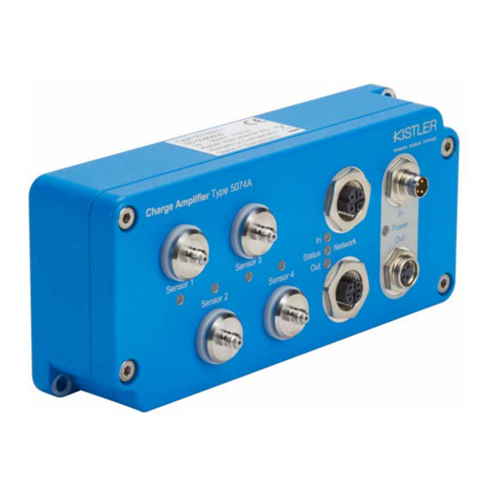
- Page 1 Instruction manual Digital industrial charge amplifier Type 5074A... ä Valid from Firmware Version 1.0.18 5074A_002-818e-06.18...
- Page 2 Instruction manual Digital industrial charge amplifier Type 5074A... ä Valid from Firmware Version 1.0.18 5074A_002-818e-06.18...
- Page 4 Information in this document is subject to change without notice. Kistler reserves the right to change or improve its products and make changes in the content without obligation to notify any person or organization of such changes or improvements.
-
Page 5: Table Of Contents
Digital industrial charge amplifier Type 5074A Content Introduction ..........................4 For your safety ........................5 Electromagnetic compatibility (EMC) ..................5 Warnings and their relevance .....................5 Disposal instructions for electrical and electronic equipment ..........6 Software upgrades and updates ..................6 Fundamentals ..........................7 Piezoelectric measurement ....................7 The industrial charge amplifier ...................9 Description of the Type 5074 charge amplifier ...............10 Block diagram ........................11... - Page 6 4.2.7 Ethernet/IP (Integration into Studio 5000, Rockwell Automation) ......36 4.2.7.1 Addressing Methods ................36 4.2.7.2 Available Assemblies ................36 4.2.7.3 Vendor-specific Objects ...............37 4.2.7.4 LED codes ...................39 Maintenance and diagnostics ....................40 Services ..........................40 Drift ...........................40 Technical Data ...........................43 AGlossary ..........................47 Measurement Uncertainty ....................50 Linearity ..........................51 Frequency Range ......................53 Influence of Temperature ....................55...
-
Page 7: Introduction
General know-how about PLC control system setup, programming and device integration is required. To the extent permitted by law Kistler does not accept any liability if this instruction manual is not followed. Kistler offers a wide range of products for use in measuring technology: ƒ... -
Page 8: For Your Safety
If any of the above indicate that safe operation is no lon- ger ensured, the device must be immediately sent to the responsible Kistler sales center or distributor for repair. 1.2 Electromagnetic compatibility (EMC) The Type 5074A… charge amplifier is manufactured in con- formity with CE requirements. -
Page 9: Disposal Instructions For Electrical And Electronic Equipment
This device does not allow Firmware update by custom- er. Please get in contact with you Kistler Service Center in order to check options to update your device to the latest Firmware. -
Page 10: Fundamentals
Fundamentals 2. Fundamentals The typical measuring chain consists of a piezoelectric sen- sor with charge output, a charge amplifier and a system for cycle command, data acquisition and data evaluation. In industrial applications, cycle command functionality is usually implemented with a programmable logic controller (PLC). - Page 11 Polarity Kistler defines polarity in such a way that an increase in compressive force in a force sensor produces a negative charge. The charge amplifier inverts the sensor signal and in this case generates a positive output voltage.
-
Page 12: The Industrial Charge Amplifier
Fundamentals 2.2 The industrial charge amplifier In this context it should be noted that the term "charge am- plifier" does not mean a device that amplifies a charge Q1 to a value Q2. We use it in the sense of a device for con- verting the charge Q into a voltage U . -
Page 13: Description Of The Type 5074 Charge Amplifier
Integration into the control environment is carried out as with a standard fieldbus device using the programming in- terface of the PLC manufacturer and the device description file which is provided by Kistler. Functions and parameters The feature set of the 5074A... may be configured to meet the effectively required functionality. -
Page 14: Block Diagram
Description of the Type 5074 charge amplifier 3.1 Block diagram 3.2 Dimensions 5074A_002-818e-06.18 Page 11... -
Page 15: Ordering Information
Digital industrial charge amplifier Type 5074A 3.3 Ordering information Charge amplifier Typ 5074A Inputs 1-channel charge 2-channel charge 3-channel charge 4-channel charge Sensor connection socket KIAG 10-32 UNF neg. – IP67 Industrial Ethernet type EtherCat EtherNet/IP ProfiNet * Y- Modification options, realization on request Ordering example 1-channel, KIAG 10-32UNF neg., EtherCat: 5074A111 3.3.1 Included accessories... - Page 16 Description of the Type 5074 charge amplifier Network connection cable, 1200A195B0,2 plug M12 male 4-Pole D-coded, plug M12 male 4-Pole D-coded, length 0.2m Power cable, 1200A239A2 plug M8 male 4-Pol open end, length 2m Power cable, 1200A239B0,2 plug M8 male 4-Pol plug M8 female 4-Pol, length 0.2m 5074A_002-818e-06.18 Page 13...
-
Page 17: Commissioning
Type 1003 cleaning spray or white spirit. ƒ Connect the cable to the sensor. We recommend using high-insulation, low-noise cables from the Kistler range. These are tested specifically for high insulation resistance, low noise and low unwanted (triboelectric) charge pro- duced by friction. -
Page 18: Led Codes
Commissioning 4.1.2 Led Codes Blink codes for Network are implemented according to net- work standards, while blink codes for each channel are im- plemented according to Kistler standards. Sensor-LEDs per channel Initialization Flashing yellow with 5 Hz Reset Flashing blue with 5 Hz... -
Page 19: Emc And Ground Loops
Digital industrial charge amplifier Type 5074A 4.1.4 EMC and ground loops Piezoelectric sensors are usually designed so that one of the electrodes is connected on the sensor case, allowing the use of coaxial cables. So when the sensor is installed, it is usu- ally grounded by the metal structure (safety). -
Page 20: Plc Integration
Commissioning Potential differences between sensor inputs On multi-channel 5074A2xx, 5074A3xx and 5074A4xx it is important to consider, that sensor connector grounds are internally connected and capacitive coupled to the housing. It is therefore recommended to electrically insulate the sen- sors in order to prevent electrical current flow due to po- tential differences between sensor locations, or to take ade- quate counter measures. - Page 21 Digital industrial charge amplifier Type 5074A 1. Start of measurement by activating control bits operate and peak control (confirmed with the status bits) 2. To eliminate unwanted peak values, toggling the peak control off and on will reset the peak values to the instant value 3.
-
Page 22: Channel Operation (Cyclic Communication)
Commissioning 4.2.1 Channel operation (cyclic communication) This is the «real-time» content which transports normal Process data and Signals and causes permanent load on the Ethernet-Frames. Cyclic data shall be kept reduced to the effectively needed information only as the amount of cyclic data has impact on possible cycle (refresh) rate Structure of output data block: Name... -
Page 23: Cyclic Operation Parameters
Digital industrial charge amplifier Type 5074A 4.2.1.1 Cyclic operation parameters Bit 0. Measure/Operate (1 Bit, Default = 0 / Reset) 120,00 Used to start and stop the charge amplifier signal acquisi- 100,00 80,00 tion and is valid for the corresponding channel only (single 5074A value 60,00 channel control). -
Page 24: Cyclic Measurement Data
Commissioning actual measuring values. Successful status change is con- 120,00 firmed with status bit «peak state». 100,00 80,00 Bit 2. Integral calculation active 5074A value 60,00 5074A peak (1 Bit, Default = 0 / off) 40,00 Used to reset/start and stop the internal integral calculation 20,00 of the corresponding channel and is active only during oper- 0,00... -
Page 25: Cyclic Status Bits
Digital industrial charge amplifier Type 5074A Integral value (REAL, 4 Byte) This data type contains the integral value which is calcu- lated inside the FPGA within a measurement cycle, respec- tively while the control Bit 2 «integral control active» is ac- tive. -
Page 26: Error Codes
Commissioning Bit 5. Overload (1 Bit, Default = 0 / off) Signalizes that the configured range got exceeded since set- ting the corresponding channel active and stays high un- til the next reset-cycle. Internal hard integrator (capacitor) overload will set Overload + Error until reset cycle. Bit 6. -
Page 27: Channel Configuration (Acyclic Communication)
Digital industrial charge amplifier Type 5074A Hardware over- Charge Integrator reached Error - Charge Input induced too high load the Charge maximum load for this range Solution: adjust range setting to have the larger capacitor selected. Parameter out of The combination of Scaling Error - Physical Range in pC exceeded Range... - Page 28 Commissioning User parameter (Acyclic): Parameter name Parameter Type Length Default (Byte) Scaling divisor FLOAT (pC/phys. Quan- tity) Range FLOAT (physical quantity) 1,000,000 Filter-frequency Enum - No filter (20kHz) (0) - 10000 Hz (1) - 5000 Hz (2) - 2000 Hz (3) - 1000 Hz (4) - 500 Hz (5) - 200 Hz (6)
- Page 29 Digital industrial charge amplifier Type 5074A Measuring range (REAL 4 Byte) Default = 1 000 000 [pC]; The parameter may be interpreted as the physical unit de- fined through the scaling divisor. With a scaling divisor = 1, 120,00 the measuring range could be interpreted in pC. 100,00 80,00 If a sensor specific scaling is applied using the divisor from...
-
Page 30: Advanced Features Description
Commissioning 4.2.4 Advanced features description Synchronization Synchronization is an important feature for deterministic «real-time» operations and required for the oversampling feature! By synchronizing the internal clocks of the devices, a pre- cise time allocation of down to 1us is possible. This allows collecting data from different slaves with the same defined time stamp for precise data processing with very low time jitter. -
Page 31: Ethercat (Integration Into Twincat 3, Beckhoff)
Digital industrial charge amplifier Type 5074A 4.2.5 EtherCat (integration into TwinCat 3, beckhoff) Installation into TwinCat™ is done using the GSD File and shall be carried out as described in the PLC Supplier’s online information system. After configuration of the Hardware structure, the Type 5074 is listed in the Devices tree and allows access to its cyclic data and configuration. -
Page 32: Available Pdos
Commissioning “Scaling Divisor” -3,9 (to be interpreted as sensor sensitivity, e.g. from calibration sheet -3,9 pC/N) “Filter Frequency” selection 4.2.5.2 Available PDOs The PDO List of the Type 5074 can be configured individ- ually to provide the required data from each measuring channel. -
Page 33: Configuration During Operation
Digital industrial charge amplifier Type 5074A 4.2.5.3 Configuration during operation It is common for some applications, that measuring range and scaling divisor of a measuring channel need to be ad- justed during a full process cycle. Using CoE commands, new configuration data for measur- ing channels can be sent to the Type 5074 for channel ad- justment. - Page 34 Commissioning Parameter Meaning Para- Length Count Max.count Access Ethercat object name meter (Byte) (4 chan- protection type channel nels) SerialNo Serial number String – read: 0x8000:01 protected write: protected ElecRang Electrical range in Float read: none 0x8000:02+n pC. Calculated by write: n.a.
-
Page 35: Led Codes
The amplifier is listed under: Other field devices Profinet IO Sensors Kistler Instrumente AG Amplifiers The device shows up with slot 0, and slots 1-4. In slots 1-4 one out of five channel modules can be inserted. -
Page 36: Records
Commissioning Modul-name Content structure Length (Byte) Startup-parameter Analog channel Control (8-Bit Bitfield) Output: 1 Piezo Scaling Divisor 16-Bit-Int Scaled Channel Range Status (8-Bit Bitfield) Input: 3 Filter-Frequency Int Value (Integer16) Time constant Analog channel Control (8-Bit Bitfield) Output: 1 Piezo Scaling Divisor 32-Bit-Float Scaled Channel Range Status... -
Page 37: Irt
Digital industrial charge amplifier Type 5074A 4.2.6.3 IRT is required for cycle times faster than 1ms. Synchronized sampling is available for 16-Bit-Int Scaled Modules. Configuration of the Master and Slave devices as IRT devic- es and assignment of the corresponding hardware connec- tions as well of the synch domain is required to setup IRT. -
Page 38: Led Codes
Commissioning Password Writing password String – none 0x020A which defines access level im- plicitly Parameter Meaning Para- Length Count Max. Access Profinet Index name meter (Byte) count protection type channel (4 chan- nels) CalGain Gain Factor for Float read: pro- 0x1000- (FactoryGain) each range... -
Page 39: Ethernet/Ip (Integration Into Studio 5000, Rockwell Automation)
Digital industrial charge amplifier Type 5074A 4.2.7 Ethernet/IP (Integration into Studio 5000, Rockwell Automation) 4.2.7.1 Addressing Methods The Charge Amplifier Type 5074 supports following ad- dressing methods: • DHCP (default) • BOOTP • Stored Value By default, the DHCP method is activated. For setting up the DHCP server, the MAC-address printed on the housing must be used. -
Page 40: Vendor-Specific Objects
Commissioning 4.2.7.3 Vendor-specific Objects All accessible parameters which are necessary to control the basic settings of the Charge Amplifier Type 5074 are cov- ered within vendor-specific objects. These can be accessed by using CIP-messages on the objects 0x80 to 0x88. Every vendor-specific object has its own Object Attributes described in Table 1: Object Attributes. - Page 41 Digital industrial charge amplifier Type 5074A 4.2.7.3.2 Class ID 0x81 – Error-Code object Attr ID Access rule Name Data Type Error-Code WORD Table 3: Instance attributes 0x81 4.2.7.3.3 Class ID 0x82 – Device Data Object Attr ID Access rule Name Data Type Get*/Set* Serial-number...
-
Page 42: Led Codes
Commissioning 4.2.7.3.6 Class ID 0x85 – In-Field Calibration Object Attr ID Access rule Name Data type Set* In-Field Calibration 1 REAL Set* In-Field Calibration 2 REAL Set* In-Field Calibration 3 REAL Table 7: Instance attributes 0x85 4.2.7.3.7 Class ID 0x88 – Device Access Object Attr ID Access rule Name... -
Page 43: Maintenance And Diagnostics
Kistler Sales Responsible or the Kis- tler Office near you. If you need additional help beyond what can be found ei- ther online or in this manual, please contact Kistler's exten- sive support organization. 5.2 Drift It is recommended to have the charge amplifier powered... - Page 44 Please make sure, that the internal time constant functionality is not activated, since this would result in such behavior. To rectify the defect, return the charge amplifier to the responsible Kistler sales center/distributor for repair. Cause 2 The signal at the output drifts linearly in the positive or neg- ative direction.
- Page 45 The zero of the charge amplifier input stage can be recalibrated if the problem persists. Send the amplifier to the responsible Kistler sales center/distributor to have this carried out. Cause 3 is readily diagnosed by removing the sensor and sensor cable and connecting a charge calibrator for testing.
-
Page 46: Technical Data
Technical Data 6. Technical Data Charge amplifier Number of channels 1, 2, 3, 4 Measurement range per channel (FSO) pC max. ±20 … 1 000 000 Measurement error with FSO ≥100 pC % FSO <±0,5 Measurement error with FSO <100 pC % FSO <±1,0 Drift... - Page 47 Digital industrial charge amplifier Type 5074A Data acquisition Resolution (delta-sigma) bits Sampling rate ksps Group delay for signal conditioning µs (plus group delay for low-pass filter) 1…20 000 4th order low-pass filter (type: Bessel) in stages 1/2/5/10 Cutoff frequency (-3 dB) per decade filter off = 20 000 Group delay (complete system)
- Page 48 Technical Data Overvoltage resistance, 40 ms/max Electrical isolation against measuring <50 circuit and digital inputs typ. (not safe- ty-relevant) Industrial Ethernet communication Hardware Standard Ethernet IEEE 802.3 100 Base-Tx Transformer-coupled Profinet IO Slave as per PNO standards Provision for supported protocols for RT, IRT Minimum update rate μs...
- Page 49 Digital industrial charge amplifier Type 5074A 1 000 1 000 1 000 1 000 Table 2: Relationship between synchronized oversampling data and attainable cycle times Page 46 5074A_002-818e-06.18...
-
Page 50: Aglossary
Cable capacitance The cable capacitance, and thus the length of the connecting cable, has no noteworthy influence on the measuring result when Kistler special cables and Kistler charge amplifiers are used. Calibrated range Measuring range or part of the measuring range for which the sensor has been calibrated. - Page 51 Digital industrial charge amplifier Type 5074A Examples: ƒ additional bending moment acts on a force sensor: F ƒ additional axial force acts on a torque sensor: F M ƒ additional shear force acts on a force/torque sensor: F and F ...
- Page 52 Describes the ability of Kistler sensors and charge amplifiers to undertake short-term measurements or DC-similar mea- surements. Range see "Measuring range"...
-
Page 53: Measurement Uncertainty
Digital industrial charge amplifier Type 5074A Sensor System which produces a definite change in the output signal as a function of the change of the measurand acting on it. Note: The term "Sensor" is equivalent to "Transducer" Temperature influence see Annex 8.4. Threshold Largest change in the measurand that produces a measur- able change in the sensor output, while the change of the... -
Page 54: Linearity
Errors due to zero drift caused by influences changing with time, such as the tem- perature, are thus basically excluded. With Kistler piezoelectric measuring chains, a typical repeat- ability within 0,1 % FSO can be assumed. 7.2 Linearity... - Page 55 Digital industrial charge amplifier Type 5074A closeness of the calibration curve to a "best straight line" passing through the zero point: "Best Straight Line“ – A line midway between the two par- allel straight lines closest together and enclosing all Output vs.
-
Page 56: Frequency Range
Glossary Hysteresis The maximum difference in output, at any measurand value within the specified range, when the value is approached first increasing and then decreasing measurand (source: ANSI/ISA-S37.1). Note: The quartz crystal itself has a scarcely measurable hys- teresis. However, the mechanical construction of the sensor can result in slight hysteresis. - Page 57 Digital industrial charge amplifier Type 5074A Phase response ϕ -180 0.01 In their dynamic behavior, piezoelectric sensors are superior to all other measuring methods. Their high rigidity results in the highest possible natural frequencies. Piezoelectric sen- sors are thus ideal for measuring measurands which change rapidly over time.
-
Page 58: Influence Of Temperature
Glossary 7.4 Influence of Temperature Temperature changes during a measurement result in an er- ror signal in the form of a zero drift. In critical applications, we recommend that protection be provided for the sensor as far as possible against changes in temperature. Temperature error of the zero point (static error) Temperature error [unit of the measurand/°C] is the great- est change to the output signal in a specified measuring... - Page 59 Digital industrial charge amplifier Type 5074A Temperature coefficient of sensitivity Change in the sensitivity, i.e. the slope of the best straight line, as a function of temperature. The temperature distri- bution in the sensor is assumed to be homogeneous, and in thermal equilibrium with the environment.
-
Page 60: Ec Declaration Of Conformity
EC Declaration of Conformity 8. EC Declaration of Conformity 5074A_002-818e-06.18 Page 57...
Need help?
Do you have a question about the 5074A Series and is the answer not in the manual?
Questions and answers