Table of Contents
Advertisement
Quick Links
Warning notices: Before using this product, please read this manual carefully and keep it for future reference.
The design and specifications are subject to change without prior notice for product improvement.
Consult with your dealer or manufacturer for details.
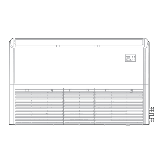
The diagram above is just for reference. Please take the appearance of the actual product as the standard.
CEILING & FLOOR TYPE AIR CONDITIONER
USER MANUAL
MODEL NUMBER:
MUEU-18HRFNX(GA)
MUE-24HRFNX(GA)
MUE-36HRFNX(GA)
MUE-48HRFNX(GA)
MUE-55HRFNX(GA)
Advertisement
Table of Contents


Need help?
Do you have a question about the MUEU-18HRFNX and is the answer not in the manual?
Questions and answers