
Related Manuals for Alpha Moisture Systems SADPm


Summary of Contents for Alpha Moisture Systems SADPm
- Page 1 MODEL SADPµ Portable Dewpoint Meter Instruction Manual Alpha Moisture Systems Alpha House 96 City Road Bradford BD8 8ES England Tel: +44 1274 733 100 Email: info@amsystems.co.uk Web: www.amsystems.co.uk...
- Page 2 Page - i -...
- Page 3 Model SADPµ Automatic Dewpoint Meter Instruction Manual Doc No: 1456 Issue 7 16/06/22 Page - ii -...
-
Page 4: Table Of Contents
Index General Description ..........................1 Ranges ............................1 Cabinet ............................1 Safety Information ..........................1 Warnings ............................1 Instructions specific to hazardous area installations ..............2 Special Conditions of Use - (denoted by the X after the certificate number) ....... 2 Pressure Exposure ......................... -
Page 5: General Description
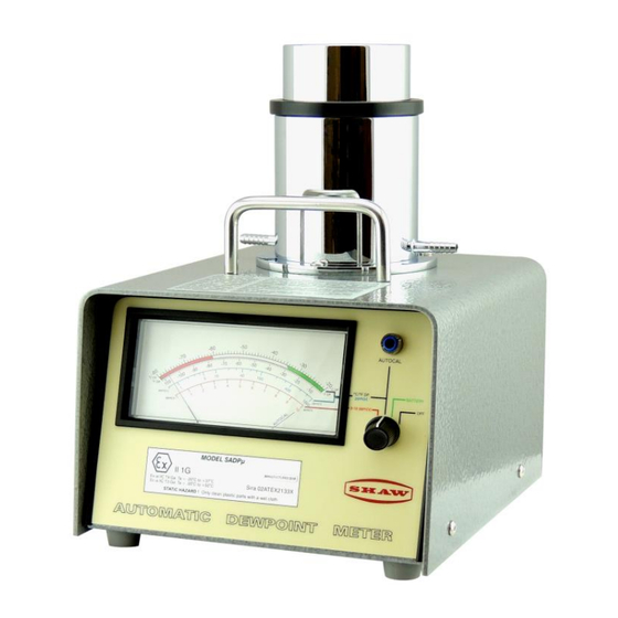
1 General Description • The SADPµ is a battery operated portable unit designed for spot check or continuous use, and gives direct indication in Dewpoint temperature and parts per million on a 12cm. analogue scale. • The SADPµ is fitted with a microprocessor based PCB which allows very accurate calibrations to be performed. -
Page 6: Instructions Specific To Hazardous Area Installations
2.2 Instructions specific to hazardous area installations The following instructions apply to equipment covered by certificate Sira 02ATEX2133X: • The certification marking is as follows: • The equipment may be used in zones 0, 1 and 2 with flammable gases and vapours with apparatus groups IIA, IIB &... -
Page 7: Pressure Exposure
2.4 Pressure Exposure The maximum pressure to which the telescopic measuring head is exposed must not be more than 0.3barg, 4.35psig, 30kpag or 0.3kg/cm Exposing the measuring head to higher pressures may damage the instrument and result in injury to the operator or other personnel in the area 3 Installing the Air/Gas Sampling System The piping installation schematic diagram (see section 3.2) shows all components, which could be used in a dry gas measurement application although not all the items shown will be required for... -
Page 8: Piping Installation Schematic
3.2 Piping installation Schematic Main Process Line Notes The sample point should be on the upper surface of the horizontal pipe, or from a vertical section of pipe, wherever possible. The sample tube should run upwards from the sample point. If this is not possible, then an inspection port or drain tap should be installed at the lowest point in the sample system. -
Page 9: Purging The Sample Connection
5. Flow Control Valve – This can be a separate item or combined with the flow indicator (8). 6. Sample Connection 7. SADP. 8. Flow Indicator – The recommended sample flow is >5 L/M. 9. Sample Exhaust – The exhaust is vented to atmosphere or returned to an atmospheric pressure line. -
Page 10: Field Calibration
Note: - Being a digitally controlled circuit, changes in value can be seen to move in a series of small steps (0.3ºC). This is also normal. Connect the PTFE sample tube to the air or gas sample point. Open the sample point to allow a flow of air of gas through the sample tube at a rate of between 5 and 15 L/min., exhausting to atmosphere. -
Page 11: Factory Calibration
Raise the head of the instrument by hand and pump it up and down carefully a few times, ending in the raised position. After about 1 minute (not critical, but not more than a few minutes) check the instrument reading. It should display the maximum level of Dewpoint for the instrument (i.e. -
Page 12: The Sensor
Note: -The factory calibration of the instrument should be verified on a yearly basis. 9 The Sensor Construction of the sensor starts with an ultra-high purity aluminium wire, which is coated with a hygroscopic layer and finally covered by a film of porous gold. The gold film and the aluminium core form the plates of the capacitor. -
Page 13: Desiccant
10.2 Desiccant The sensor is kept dry when not in use by the desiccant contained in the head assembly. The instrument is designed to maintain the sensor below –70ºC Dewpoint as this maintains the optimum responsiveness of the sensor. The above readings should be obtained when the instrument has been left with the head in the closed position for a few hours e.g. -
Page 14: Problem Guide
11 Problem Guide PROBLEM CAUSE SOLUTION ERRATIC READINGS Static on Indicator Moisten indicator face with 50/50 mixture of detergent & water, or use proprietary anti- static cleaner. DO NOT POLISH INDICATOR FACE. FULL SCALE READING Wet gas Stop gas supply & switch analyser off. Short Circuit Cable or Plug Disconnect plug from sensor &... -
Page 15: Problem Guide (Continued)
11.1 Problem Guide (Continued) PROBLEM CAUSE SOLUTION WET READING Leak in System or use of Cure leak, or replace unsuitable pipe Unsuitable Pipe with copper or stainless steel. Flexible connections should be made with PTFE pipe. NEVER use rubber or plastic pipe. Comparison with Secondary Ensure that samples are taken from Standard Instrument or... -
Page 16: Hygrometric Equivalents
12 Hygrometric Equivalents Page - 12 -...
Need help?
Do you have a question about the SADPm and is the answer not in the manual?
Questions and answers