
Related Manuals for Alpha Moisture Systems dewTEC DS2000


Summary of Contents for Alpha Moisture Systems dewTEC DS2000
- Page 1 DS2000 dewpoint meter instruction manual alpha moisture systems alpha house, 96 city road bradford, BD8 8ES england Tel: +44 1274 733100 Fax: +44 1274 733200 Email: info@amsystems.co.uk Web: www.amsystems.co.uk...
- Page 2 DS2000 User’s Manual Page ii...
- Page 3 Section 1 General Description Includes general description outlining the main features of the unit. Section 2 Installation Instructions Safety Information Unpacking your dewTEC DS2000 and Moisture Sensor Sensor Care Sensor Installation Dew Point Meter Installation Electrical Connections External AUTOCAL Control...
- Page 4 DS2000 User’s Manual Page iv...
-
Page 5: Table Of Contents
Sensor Features Installation Instructions Safety Information 2.1.1 Warning 2.1.2 Isolation Unpacking your dewTEC DS2000 Dewpoint Meter and Sensor Sensor Care Installing the air/gas sampling system Installing and commissioning the sensor Installing your dewTEC DS2000 Hygrometer 2.6.1 Panel mounting cut out 2.6.2... - Page 6 DS2000 User’s Manual Page vi...
-
Page 7: General Description & Features
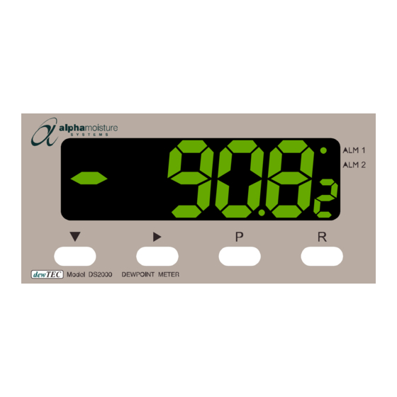
The operating range of the unit is factory set to the Moisture Sensor supplied with the unit. Process moisture value in factory set units of °C, °F or PPM(V) is indicated, by the dewTEC DS2000 dewpoint meter, on a large five digit seven segment display The main external body of the Ultra High Capacitance Moisture Sensor is made of plated steel and a stainless steel filter guard protects the sensing element within it. -
Page 8: Installation Instructions
Once unpacked, the items should be examined for any obvious external damage. Any evidence of damage or mishandling should be notified to your carrier immediately. The items should include dewTEC DS2000 dewpoint meter, Moisture Sensor packed in a metal canister, instruction manual, sensor connecting cable and any optional extras if ordered. -
Page 9: Installing The Air/Gas Sampling System
• Ensure the sample gas exposed to the sensor is clean as contaminants such as oil, glycol and heavy hydrocarbons can mask the sensing element, thus affecting the system response. (If this is an issue contact your dewTEC DS2000 supplier for advice on a suitable sample system.) - Page 10 If the air/gas sample contains heavy hydrocarbon condensate, the filter must be of the coalescing type with a drain. The filter unit should be positioned as close to the sample point as practical. dewTEC DS2000 User’s Manual Page 4...
-
Page 11: Installing And Commissioning The Sensor
Set the required pressures and flows within the sample loop. This completes the installation and commissioning but, on initial start-up, it could take several hours for the system to reach equilibrium. dewTEC DS2000 User’s Manual Page 5... -
Page 12: Installing Your Dewtec Ds2000 Hygrometer
Installing your dewTEC DS2000 Hygrometer The dewTEC DS2000 is a standard 1/8 -DIN size. 2.6.1 Panel mounting cut out The panel on which your hygrometer is to be mounted must be rigid and up to 6mm thick. The cut out size required is shown in the diagram below. -
Page 13: Mains (Line) Supply
Load Impedance is 500Ω maximum in mA ranges and 500Ω minimum in voltage ranges. 2.7.5 Alarm Transistor Open Collector Outputs The open collector outputs of Alarm 1 and 2 are NPN outputs. The return is common for both collectors. dewTEC DS2000 User’s Manual Page 7... -
Page 14: Serial Communications Output
(see section 4). T w i s t e d p a i r o r s c r e e n e d c a b l e 2 0 k Ω dewTEC DS2000 User’s Manual Page 8... -
Page 15: Operating Instructions
When pressed simultaneously in Edit Mode, the unit will abort the Edit operation ( ) & ( ) and will restore the parameter to its initial value. ALM 1 and ALM 2 LED Indicators lit (in all operation modes) when in alarm condition. dewTEC DS2000 User’s Manual Page 9... -
Page 16: Viewing Operating Mode Parameters
DEWPOINT METER PRESS PRESS Automatic display change if there NOTE: These displays is no key activity after 3 seconds will not appear if the Help function is disabled Display change due to key activity dewTEC DS2000 User’s Manual Page 10... -
Page 17: Setting The Alarms And Hysterisis
PRESS Display is now back in operating mode at the point where the setting mode was entered. ALM 1 ALM 1 ALM 2 ALM 2 To abort at any stage. PRESS dewTEC DS2000 User’s Manual Page 11... -
Page 18: Hysterisis Operation
If Alarm 1 is configured to be a latching alarm relay when it is active, it can be reset as follows: Ensure Dewpoint is displayed Press reset key (R) Note, the latched alarm cannot be reset whilst the alarm condition persists. dewTEC DS2000 User’s Manual Page 12... -
Page 19: Hygrometer Settings
3. IF NECESSARY, adjust the Autocal control, on the analyser front panel, until the display indicates the maximum level for the sensor range in use. dewTEC DS2000 User’s Manual Page 13... -
Page 20: Programmed Settings
We recommend that verification of the overall linearity of calibration of the system should be carried out on a 12 monthly basis. Programmed Settings The dewTEC DS2000 has two setting modes that modify the hygrometers’ operation. The modes and parameters are shown in the following table: MODE... - Page 21 Display shows the parameter description for 3 setting. seconds before a parameter value is shown. Remember that if Help is enabled, the Primary Display shows the Displays given above and the parameter value after three seconds. dewTEC DS2000 User’s Manual Page 15...
-
Page 22: Configuration Mode
Relay 1 operate Alarm 1 latching, User adjustable direct action setting Alarm 1 latching, reverse action Logical OR Alarms 1 & 2, direct action Logical OR Alarms 1 & 2, reverse action dewTEC DS2000 User’s Manual Page 16... - Page 23 4 – 20mA Communications Enable/Disable None/Disabled Comms. Enabled User adjustable Only disable this function if comms. is setting Not available giving you a problem. Not available Totaliser Timebase. Seconds User adjustable Minutes setting Hours dewTEC DS2000 User’s Manual Page 17...
-
Page 24: Serial Communications
Laa??* where aa is the address (a two digit hexadecimal number). The reply from the addressed instrument is of the form: Laa?A* Where aa is the same address as in the received message. dewTEC DS2000 User’s Manual Page 18... -
Page 25: Message Form
No Reply timeout in each case. Parameter read operations with parameter identifiers which are not applicable to the addressed instrument, will have no effect and a positive acknowledgement will be returned. dewTEC DS2000 User’s Manual Page 19... -
Page 26: Maintenance And Troubleshooting
6.0 Maintenance and Troubleshooting Maintenance The dewTEC DS2000 front panel can be wiped clean when necessary with a damp soft cloth. The hygrometer contains no user serviceable parts. Do not open the unit. The rear of the unit can be dusted with a dry cloth if necessary. Ensure that no voltages are present on the rear terminal when this is done. - Page 27 (colder) than the DP temperature of the sample gas. Once having formed, the sample reaching the sensor will have a DP equal to the temperature of the condensate, regardless of the DP at the sample point dewTEC DS2000 User’s Manual Page 21...
-
Page 28: Appendices
7.5VA max 11. Physical Dimensions: Height – 48mm Width – 95mm Depth – 110mm without sensor connector. Weight 0.21 kg max. Mounting: Panel-mount; press-fit fixing. Panel cut out – 45mm x 92mm. Terminals: Screw type dewTEC DS2000 User’s Manual Page 22... -
Page 29: Appendix B - General Arrangement
Appendix B – General Arrangement dewTEC DS2000 User’s Manual Page 23...
Need help?
Do you have a question about the dewTEC DS2000 and is the answer not in the manual?
Questions and answers