
Subscribe to Our Youtube Channel
Related Manuals for Alpha Moisture Systems SADPminiEx


Summary of Contents for Alpha Moisture Systems SADPminiEx
- Page 1 Model SADPminiEx Instruction Manual Alpha Moisture Systems Alpha House 96 City Road Bradford BD8 8ES England Tel: +44 1274 733100 Fax: +44 1274 733200 Email: mail@amsytems.co.uk Web: www.amsystems.co.uk...
- Page 2 Page ii...
- Page 3 Page iii...
- Page 4 Instruction Manual For the SADPminiEx Automatic Dewpoint Hygrometer 1405 SADPminiEx User Manual.doc Issue 7.2 31/10/14 Page iv...
-
Page 5: Table Of Contents
Table of Contents ......................1 ENERAL NFORMATION ..........................1 EATURES ........................... 2 ANGES ............................ 2 ASING ......................2 AFETY NFORMATION ..........................2 ARNING ) ..... 2 PECIAL ONDITIONS OF DENOTED BY THE AFTER THE CERTIFICATE NUMBER ........................ 3 RESSURE XPOSURE .......................... - Page 6 11.2.3 PC Comms ............................20 11.2.4 Delete Data ............................. 21 11.2.5 Create TAG ............................. 21 11.2.6 Edit TAG ............................21 11.2.7 Delete TAG ............................. 22 11.2.8 Printer LOG ............................ 22 11.2.9 Unit Address ............................ 23 11.2.10 Free Space..........................23 11.2.11 Exit ............................
-
Page 7: General Information
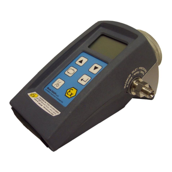
1 General Information The SADPminiEx is a battery powered portable instrument, consisting of an aluminium oxide sensing element and associated printed circuit boards. Also incorporated in the device is LCD indication, membrane keypad, RS485 interface, 4-20mA interface, charger socket and sample inlet and outlet ports. -
Page 8: Ranges
Ex ia IIC T3 ( Ta = – 20ºC to +50ºC ) It is the responsibility of the user to ascertain the suitability of the SADPminiEx for use in hazardous areas. Risk assessments should be performed prior to use taking into account the SADPminiEx certifications, the ‘x’... -
Page 9: Pressure Exposure
Note: There are no serviceable parts within the encapsulated battery. 3.4.2 Initial Charging It is recommended that the SADPminiEx be put on charge overnight when first received, the unit should be turned OFF during charging. Only use the Charger supplied with... -
Page 10: Gases To Avoid
Care should be taken to ensure that the sample presented to the SADPminiEx is not contaminated with any component that will damage, contaminate or affect the SADPminiEx in a way that will impair the unit’s accuracy. It is strongly recommended that the sample should not contain particulate matter, oil, hydrocarbon or any other condensate. -
Page 11: Piping Installation Schematic
4.2 Piping installation Schematic Main Process Line Notes The sample point should be on the upper surface of the horizontal pipe, or from a vertical section of pipe, wherever possible. The sample tube should run upwards from the sample point. If this is not possible, then an inspection port or drain tap should be installed at the lowest point in the sample system. -
Page 12: Purging The Sample Connection
6 Using the SADPminiEx to take a Moisture Reading Refer to the sample system schematic in section 4.2. The first purpose of the SADPminiEx is to provide a rapid, easy and reliable means of carrying out moisture content measurements, of gases. To ensure rapid response the sensor is kept dry by surrounding the sensor with desiccant in the head assembly when it is not in use. - Page 13 The SADPminiEx can display moisture readings in any one of six Engineering Units and can also display pressure compensated readings. The SADPminiEx should be setup as required (See The Setup Menu section) before progressing to take sample readings Page 7 of 33...
-
Page 14: Taking A Measurement
Head Lowered Head Raised Restrict the outlet of the SADPminiEx (7) by placing a finger over the sample exhaust (9), so that the pressure of the sample lifts the telescopic head. As soon as the head is fully extended remove the finger, to prevent pressure build up. Pull gently on the head to make sure it is fully extended. -
Page 15: Sample Pipe
7.1 Sample Pipe The SADPminiEx is supplied with 2 connections: a “fir tree” on one side and a Swagelok ® compression fitting for in, or 6mm OD pipe (as specified on your order) on the other. Either can be used as the inlet connection (6). -
Page 16: Liquid Contamination
8 SADPminiEx Initial Configuration Each SADPminiEx is set up prior to despatch to the end users specification. The following values will be preset: - The specified sensor type is pre-selected. -
Page 17: The Normal Display Screen
9 The Normal Display screen When the SADPminiEx is ON, it displays the moisture level of the gas that the sensor is exposed too. When the head is lowered, the sensor is no longer exposed to the gas and is dried down by the desiccant in the head. -
Page 18: Entering Alphanumerical Data
– This sub-menu has eight options allowing the user to select any one of seven Moisture Engineering Units and to exit the menu. Note: - 1) Once an engineering unit is selected, the SADPminiEx will only display and accept inputs in that chosen unit. This means that 4-20mA settings (where fitted), offsets and SPCs are all performed in the chosen units. -
Page 19: Pressure Calc
The default setting is for the output range to cover the full operating range of the sensor type fitted in the SADPminiEx e.g. for a ‘B’ type sensor 4mA equals –80°C and 20mA equals 20°C. However, it is possible to set a more focused range, such as 4mA equals -60°C and 20mA equals –20°C. -
Page 20: Autocal
SADPminiEx automatically reverts to the ‘Exit’ option in the ‘Setup Menu’. Note – 1) The only way to leave this menu without altering any values is to press the ‘ ’ key twice, accepting the current values for both the upper and lower settings. -
Page 21: Spc (Single Point Calibration)
Pressing ‘ ’ key again will return the instrument to operational mode. Note - Avoid carrying out the AutoCal procedure on a SADPminiEx with a full scale value of 0°C dewpoint on days when the ambient dewpoint may to be below this value, for example a dry day when the ambient temperature is below around 12°C. -
Page 22: Security
1. An AutoCal must be carried out before performing an SPC. 2. Measure the value of the reference gas with the SADPminiEx in the normal way and note the indicated value and the stated value of the “standard reference.” [For example, the SADPminiEx reads -70°C dewpoint, and the “standard reference gas”... -
Page 23: Time And Date
– In the ‘Setup Menu’ select the ‘Time and Date’ option. 11.1.8 Set Clock Description – The Clock option allows the user set the SADPminiEx internal Real Time Clock. Operation – In the ‘Setup Menu’ select the ‘Set Clock’ option. The user is prompted to enter the Date in the DD/MM/YY format followed by the time in the HH:MM:SS in 24- hour format. -
Page 24: Temperature
Transferring data to a PC cannot be performed in hazardous areas - See section 17, page 25. See also Appendix C for SADPminiEx Logging Menu Map. The Logging menu it activated by pressing the ‘’ and ‘’ keys simultaneously. From... -
Page 25: Internal Logging
20 data blocks (a file where data points are stored). This means that a maximum of 400 separate data blocks can be stored. The SADPminiEx has a capacity of 16000+ individual data points. -
Page 26: Pc Comms
The selection screen shows the TAG reference, block number plus the date & time when data was stored. The SADPminiEx by default displays the most current data block first and subsequently runs through the remaining blocks in chronological order. Pressing the ‘’ key displays the next block of information. -
Page 27: Delete Data
Operation – In the ‘Logging Menu’ select the ‘PC COMMS’ option. Ensure the SADPminiEx is connected to the PC using the cable supplied. Start the PC software (See SADPminiEx Logger software user guide) and press the ‘ ’ key twice. -
Page 28: Delete Tag
‘External LOG’ display screen, which indicates the current moisture value. Pressing the ‘’ key at any point will stop logging. Note: By default the SADPminiEx will output a moisture value in the current units every 6 seconds. Page 22 of 33... -
Page 29: Unit Address
11.2.9 Unit Address Description – It is possible to communicate with up to 32 SADPminiEx units via the RS485. However, for this to operate correctly each unit must have a different address. The default address setting for the SADPminiEx is 1. -
Page 30: Performing An Autocal
This reading is entered into the SADPminiEx in the AutoCal process as the AutoCal value. The AutoCal routine can be performed using a known reference gas or under ambient conditions. Note: The AutoCal process will automatically correct any SPCs (see section 9.2.5) already in the SADPminiEx. Page 24 of 33... -
Page 31: Ambient Conditions
14.1 Ambient conditions Pump the SADPminiEx head up and down a few times to ensure that the air surrounding the sensor in the SADPminiEx head is representative of the ambient moisture value. Leave the head out and allow the sensor to stabilise. Start the AutoCal routine and enter the ambient moisture value into the SADPminiEx when asked to enter the AutoCal Value. -
Page 32: Calculating Maximum Output Load (Rext )
Viewed from solder bucket side RS485 (A) CON066 RS485 (B) 17 SADPminiEx Logging Software Cables and Interfaces FOR USE IN SAFE AREA ONLY There are 2 types of interface that can be used with the SADPminiEx and SADPminiEx Logging software. Page 26 of 33... -
Page 33: Rs232 To Rs485 Cables & Interface
The Interface unit INT007 has two 9-way ‘D’ type connectors. The connector marked with a ‘B’ connects to a PC or Laptop serial Port using a 2.0m serial cable (Part No: CAB029). The connector marked with a ‘S’ connects to the SADPminiEx using a 1m special cable (Part No: CAB032). -
Page 34: Usb To Rs485 Cables & Interface
The Interface unit INT008 has a 9-way ‘D’ type connector and a USB connector. The USB connects to a PC or Laptop USB Port using a 1.8m USB cable (Part No: CAB031). The ‘D’ type connects to the SADPminiEx using a 1m special cable (Part No: CAB033). -
Page 35: Technical Details Of The Rs485\4-20Ma Connecter (Con066)
18 Technical Details of the RS485\4-20mA Connecter (CON066) SAFE AREA ONLY - Connecting unapproved equipment to the terminals of the instrument could cause the instrument to become unsafe for use in the hazardous area and will invalidate the intrinsically safe certification. The CON066 connecter can be wired as a 4-20mA connector or as a dedicated RS485 connecter. -
Page 36: Sadpmini Protocol
1. Fully extend the Desiccant head (1) of the SADPminiEx. 2. Unscrew the Retaining Collar (2), turning it counter clockwise (anti-clockwise), which will unfasten the desiccant filled head from the main body of the SADPminiEx. 3. Gently pull out the Desiccant Head from the main body of SADPminiEx. - Page 37 8. Fit Desiccant Head Base “O” Ring (3) 9. Insert Desiccant Head in the main SADPminiEx body and tightly screw in the Retaining Collar. Page 31 of 33...
- Page 38 Page 32 of 33...
-
Page 39: Appendix C - Sadpminiex Setup Menu Map
21 Appendix C – SADPminiEx Setup Menu Map ENTER CODE 1000 SETUP MENU SELECT UNITS PRESSURE CALC 4-20mA OUTPUT AUTO-CAL SECURITY SELECT UNITS PRIMARY UNITS ºC ºF ppm[V] ppm[W] g/m3 PRESSURE CALC PRESSURE UNITS SET PRESSURE 000.0 psig barg barg... -
Page 40: Appendix D - Sadpminiex Logging Menu Map
22 Appendix D – SADPminiEx Logging Menu Map LOGGING MENU Internal LOG Review DATA Export DATA Delete DATA Create TAG Edit TAG Internal LOG Select Log Tag LOGGING DATA Interval [Mins] TAG 1 TAG1 LOGGING Logs Free 16000 0001.0 OZZY EMPTY -11.7 ºC... -
Page 41: Appendixe - Trouble Shooting
23 Appendix E – Trouble Shooting Fault Explanation Required Action Notes Unit does not turn on. Battery low level Connect the battery charger Connecting the external Screen remains blank. unit for a minimum of 14 battery charger will not allow Back light off hours charging. -
Page 42: Appendix F - Sadpminiex Specification
100-240VAC, 50-60Hz, 400mA Output: 6VDC, 15W Battery Cell: 3.6V Li-Polymer 750mAh capacity Charging: Full Charge in 14 hours. Only use the Charger supplied with SADPminiEx Capacity Minimum of 70hrs* on full charged battery Environmental Approvals: EMC: Certified to BS EN 61000-6-3:2007... - Page 43 ‘*’ Battery capacity is quoted at room temperature. The battery capacity will degrade as the ambient working temperature falls. Page 37 of 33...
Need help?
Do you have a question about the SADPminiEx and is the answer not in the manual?
Questions and answers