Table of Contents
Advertisement
Quick Links
Advertisement
Table of Contents

Related Manuals for Alpha Moisture Systems DS1200-AMT


Summary of Contents for Alpha Moisture Systems DS1200-AMT
- Page 1 DS1200-AMT Dewpoint Analysis System Installation, Commissioning and Operation Manual Alpha Moisture Systems Alpha House 96 City Road Bradford BD8 8ES England Tel: +44 1274 733100 Fax: +44 1274 733200 Email: mail@amsytems.co.uk Web: www.amsystems.co.uk...
- Page 2 DS1200 Dewpoint Analyser Instruction Manual Issue 4 07/03/2011 1551 DS1200 - AMT User Manual...
-
Page 3: Table Of Contents
Index Safety Instructions......................1 Definitions: ............................1 Receipt and Unpacking:.........................1 Environment: ............................1 Normal Operation:..........................1 Cleaning:..............................1 DS1200/AMT System Description.................. 2 DS1200/AMT System Application:.......................2 DS1200 Technical Characteristics:......................2 DS1200 Mounting:......................2 Installing the Instrument into a Panel ....................2 Wiring ..........................2 DS1200 Power Supply...........................2 AMT Sensor Cable ..........................2 Alarm Cable............................3 Analogue Output Cable .........................3... -
Page 4: Safety Instructions
Warning! • Until the DS1200 is installed, do not connect hazardous voltages to the DS1200. • Trouble shooting of the DS1200-AMT System should only be carried out on a disconnected DS1200-AMT and under ESD safe conditions. • Repair of the DS1200 must be done by Alpha Moisture Systems, or authorised distributors, only. -
Page 5: Ds1200/Amt System Description
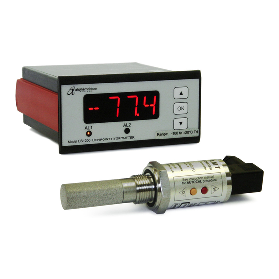
2 DS1200/AMT System Description • DS1200 has a 4-digit 14 segment LED display • Loop powered Model AMT transmitter DS1200 Input (terminals 45 & 46) • DS1200 has 2 Alarm Relays (terminals 21 to 26) • DS1200 has mA Output (terminals 11 and 12) •... -
Page 6: Alarm Cable
Note : - Do not install the sensor at this time. Wait until the commissioning stage as described later Alarm Cable • Make the appropriate connections, noting the normally open and normally closed relay contact positions. Analogue Output Cable • Make the appropriate connections, ensuring that the correct polarity and the maximum load specification is strictly observed. -
Page 7: Connector Pins
Rs max = [40 x (Vs – 7) ]Ω. If the wiring resistance is expected to be more than a few percent of the value of Rs, then this resistance must be taken away from the answer to get the maximum usable value of Rs. Connector Pins Red = 12 to 28V dc Power Supply Blue = 4-20mA Current Return... -
Page 8: Piping Installation
• The measuring sensor can be installed directly into the process line but this does create problems with access for maintenance and calibration. It is for these reasons that we recommend that the sensor be installed in a bypass, fast loop or total loss sample system where the sensor is accessible without interrupting the main process flow line. -
Page 9: Installing And Commissioning The Model Amt Transmitter
Sample Pressure Gauge – This is not a critical part of the moisture measurement but may be required if Dew/Frost point measurements are to be made at higher than atmospheric pressure. Measuring AMT Sensor. Sensor Holder. Desiccant Chamber – This item is required when the sampling is to be intermittent. When installed it prevents the ingress of wet air to the sample system, while the sample is not flowing, improving the response time. -
Page 10: Commissioning
7 Commissioning • Switch the instrument power ON. The display will read “SE.BR“. This is the 'Sensor Wire Break' display condition. Setting the Alarm Trip Points • To activate the quick alarm settings screen press either the ”▲” or ”▼” buttons, while the DS1200 is displaying the moisture level. -
Page 11: Normal Operation
8 Normal Operation Analogue 4-20mA Mode (2-wire) • In normal operation, the transmitter will produce a 4-20mA signal, which is proportional to the level of moisture in the gas being monitored. The moisture reading is sampled and up dated once per second. -
Page 12: Entering Autocal Mode
Entering Autocal Mode • Once the transmitter has been pre-conditioned, the AutoCal Mode of the AMT can be activated. Press and hold the ‘W’ and ‘D’ buttons, simultaneously for 5 seconds. ONLY PRESS THE BUTTONS IF THE SENSOR IS PROPERLY PRE-CONDITIONED. FAILURE TO COMPLY WILL CORRUPT THE TRANSMITTERS CALIBRATION. - Page 13 Page 10...
-
Page 14: Faults/Errors
10 Faults/Errors • If the sensor is short-circuited, the transmitter will produce a constant 20.75mA output. • If the sensor is open-circuited, the transmitter will produce a constant 20.50mA output. • If the hardware develops a fault, the transmitter will produce 21.0mA for 5 seconds after switch on and then continue to give an output. -
Page 15: Amt Specification
11.2 AMT Specification Display Compatible with the 4-20mA DS1200 Dewpoint Meter. Output Signal 4 to 20mA Linear Operating Voltage 7V - 28V DC. Reverse polarity protected. Maximum Series Resistance: = {40 x (Supply Voltage – 7)}Ω Sensing element Ultra High Capacitance - Aluminium Oxide Type AutoCal Field calibration / Span check facility. -
Page 16: Applicable Standards
11.3 Applicable Standards • EMC 2004/108/EC o Emissions and immunity = EN 61326 • LVD 73/23/EEC Low voltage = EN 61010-1 • UL o Standard for Safety = UL 508 Page 13... -
Page 17: Appendix A - Amt With Connector, General Arrangement
Appendix A – AMT with Connector, General Arrangement 0.625” dia 15.9ø 28mm (1.1”) 30mm A/F (1.185” A/F) Page 14... -
Page 18: Appendix B - Sensor Holder General Arrangement
Appendix B – Sensor Holder General Arrangement 68 (2.68”) 58 (2.28”) 15 (0.6”) 10 (0.4”) 43 (1.7”) Page 15...
Need help?
Do you have a question about the DS1200-AMT and is the answer not in the manual?
Questions and answers