Table of Contents
Advertisement
Quick Links
MOUNTING AND
OPERATING INSTRUCTIONS
EB 29a
Translation of the original manual
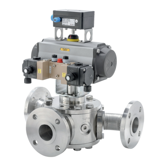
3-way Diverting valve BR 29a • DIN and ANSI version
to combine with actuators
for installation in piggable pipes
December 2023 edition
PFEIFFER Chemie-Armaturenbau GmbH · Hooghe Weg 41 · 47906 Kempen · Germany
Phone: +49 2152 2005-0 · Fax: +49 2152 1580
sales-pfeiffer-de@samsongroup.com · www.pfeiffer-armaturen.com
Advertisement
Table of Contents

Related Manuals for Samson BR 29a


Summary of Contents for Samson BR 29a
- Page 1 MOUNTING AND OPERATING INSTRUCTIONS EB 29a Translation of the original manual 3-way Diverting valve BR 29a • DIN and ANSI version to combine with actuators for installation in piggable pipes December 2023 edition PFEIFFER Chemie-Armaturenbau GmbH · Hooghe Weg 41 · 47906 Kempen · Germany Phone: +49 2152 2005-0 ·...
- Page 2 Note regarding this installation and operating manual This Installation and Operating Manual (EB) provides guidance for safe assembly and operation. The notes and instructions in this EB are binding when handling PFEIFFER devices. The fi gures and illustrations in this EB are ex- amples and must therefore be considered as such.
-
Page 3: Table Of Contents
Content Content Safety instructions and safety measures Notes regarding possible severe personnel injury Notes regarding possible personnel injury Notes regarding possible property damage Warning notes on the device Markings on the device Type plate 2.1.1 Actuator type plate Material identifi cation Design and principle of operation Variants Additional fi... - Page 4 Content Start-up Operation Malfunction Detecting and rectifying errors Carrying out emergency measures Servicing Periodic tests Maintenance work 9.2.1 Replacing the seat rings and ball Ordering spare parts and consumables 10 Decommissioning 10-1 11 Removal 11-1 11.1 Removing the diverting valve from the pipe 11-1 11.2 Disassembling the actuator...
-
Page 5: Safety Instructions And Safety Measures
Intended use relevant standards, are capable of evaluating the assigned The principle function of the BR 29a 3-way diverting valve, is to tasks and identifying possible hazards. divert the medium in different directions in the piggable pipe sys- tem. -
Page 6: Notes Regarding Possible Severe Personnel Injury
Safety instructions and safety measures − Furthermore, the operator must ensure that operating person- 1.1 Notes regarding possible severe per- nel and third parties are not endangered. sonnel injury It is not the responsibility of PFEIFFER and therefore when using the diverting valve ensure that: DANGER −... -
Page 7: Notes Regarding Possible Property Damage
Safety instructions and safety measures WARNING WARNING Danger of injury during the switching operation if performing Dangers due to use as an end fi tting! test runs on diverting valves not installed in the pipe! During normal operation, in particular with gaseous, hot and/or Do not reach into the diverting valve. -
Page 8: Warning Notes On The Device
Safety instructions and safety measures 1.4 Warning notes on the device NOTE Deviation of the breakaway and actuating forces due to Warning of moving parts non-actuation of the diverting valve! Depending on the period of time of non-actuation, the breaka- way and actuation forces can deviate considerably from the ac- tuating power data in the data sheet. -
Page 9: Markings On The Device
Manufacturer PFEIFFER Address see Chapter “15.3 Service” Valve type BR (and number value) e.g. BR 29a = Series 29a, see the PFEIFFER catalogue Body material e.g. 1.4571 Material standard according to DIN EN 10272 Size DN (and number value) Number value in [mm], e.g. DN 80 / number value in [inches], e.g. NPS3... -
Page 10: Type Plate
Markings on the device 2.1 Type plate 2.1.1 Actuator type plate See the corresponding actuator documentation. 2.2 Material identifi cation The diverting valves are marked on the body with the material specifi cation, see Table 2-1. Further details can be obtained from PFEIFFER. EB 29a_EN December 2023 edition Subject to technical changes... -
Page 11: Design And Principle Of Operation
− Seat rings in PTFE-compounds − Sealing in graphite Function and principle of operation The principle function of the 3-way diverting valve BR 29a is to divert the medium in different directions in the piggable pipe sys- tem. The ball (2) with its cylindrical passage slew around the middle axis. -
Page 12: Additional Fi Ttings
− Detailed information is available in the data sheet TB 29a. − The documentation for the special diverting valves BR 29a that Place the main body (1) on an even and clean work surface, are not described in this chapter can be requested from so that the inside of the diverting valve is easy to reach from PFEIFFER. - Page 13 Design and principle of operation Fig. 3-2: Sectional drawing of the BR 29a diverting valve Table 3-2: Parts list of the BR 29a diverting valve Item Description Item Description Main body Bearing bush Ball Disc spring set Bonnet fl ange V-ring packing Base fl...
-
Page 14: Bonnet Fl Ange Assembly
Design and principle of operation Now the disc spring set ( 14 ) is placed on the V-ring pack- Info ing. For the arrangement of the disc springs, refer to the The permissible torque for tightening the base fl ange, see Ta- drawing Fig. -
Page 15: Shipment And On-Site Transport
Shipment and on-site transport Shipment and on-site transport WARNING The work described in this chapter may only be performed by Danger of injury due to the tipping of the diverting valve! specialist personnel qualifi ed to perform the corresponding task. Observe the centre of gravity of the diverting valve. -
Page 16: Lifting Points On The Body
Shipment and on-site transport Fig. 4-1: Lifting points on the diverting valve Secure the sling against shifting and slipping off. 4.3.3 Lifting points on the body Fasten the sling such that it can be removed again after in- Fasten a lifting sling to each fl ange of the housing and on the stallation in the pipe. -
Page 17: Lifting Points On The Bracket
Shipment and on-site transport Move the diverting valve at a constant speed to the installa- The diverting valve must be stored in its protective packaging tion site. and/or with the protective caps on the connection ends. Install the diverting valve in the pipe, see chapter 5.4 Diverting valves that weigh more than approx. - Page 18 Shipment and on-site transport EB 29a_EN December 2023 edition Subject to technical changes...
-
Page 19: Installation
Installation When connecting the attachments, make sure that they can Installation be accessed from the operator level safely and easily. The work described in this chapter may only be performed by specialist personnel qualifi ed to perform the corresponding task. The following instructions apply additionally for diverting valves. -
Page 20: Installing The Diverting Valve In The Pipe
Installation WARNING Danger and damage due to use of an electrical actuator! It must be ensured that the actuator in the end positions is turned off by the limit switch signal. If shut-off takes place in an intermediate position due to the signal of the torque switch, this signal should be used in ad- dition for an error message. -
Page 21: Switch Position
Fig. 5-3. ated exhaust air can be released to the outside (protection against overpressure in the device). The supplied 3-way diverting valve BR 29a must be suitable for Furthermore, vents allow the intake of air (protection against the pipe section. -
Page 22: Fail-Safe Position
Installation 5.4.3 Fail-safe position WARNING The fail-safe position for all variants is “HOLD”. This means that if Danger of crushing due to moving actuator- and control shaft! the supply air fails, the actuator remains in its position. Do not reach into the yoke as long as the pneumatic power is connected to the actuator. -
Page 23: Rotary Movement
Installation Info The plant operator is responsible for performing the pressure test. After Sales Service at PFEIFFER can provide you with support for the planning and implementation of a pressure test specifi c to your plant. 5.5.3 Rotary movement The rotary movement of the actuator- and control shaft must be linear without any jerky movements. - Page 24 Installation EB 29a_EN December 2023 edition Subject to technical changes...
-
Page 25: Start-Up
Start-up Commissioning/recommissioning Start-up − Open the diverting valves slowly in the pipe. Opening slowly The work described in this chapter may only be performed by prevents a sudden increase in pressure and a resulting high specialist personnel qualifi ed to perform the corresponding task. fl... - Page 26 Start-up EB 29a_EN December 2023 edition Subject to technical changes...
-
Page 27: Operation
Operation of extensions to increase the actuation torque is not permit- Operation ted. As soon as the commissioning/recommissioning work is com- − In the case of diverting valves with a hand lever, the position plete, see Chapter “6 Commissioning”, the diverting valve is of the hand lever indicates the location of the bore in the ball. - Page 28 Operation EB 29a_EN December 2023 edition Subject to technical changes...
-
Page 29: Malfunction
Malfunction Malfunction When rectifying the faults, chapter “1 Safety instructions and safety measures” must be observed. 8.1 Detecting and rectifying errors Type of fault Possible cause Measures Leaks in the pipe connection The fl ange connection of the Tighten the fl ange screws. diverting valve is leaky NOTE An excessive tightening torque when retightening the fl... -
Page 30: Carrying Out Emergency Measures
Malfunction Type of fault Possible cause Measures Problems in the actuator unit The pneumatic actuator must Disconnect the connection to the control pressure. be removed Remove the actuator from the diverting valve (observe the “Safety instructions and safety measures”, see the included actuator unit manuals). -
Page 31: Servicing
Servicing Servicing NOTE The work described in this chapter may only be performed by Damage to the diverting valve due to excessively high or low specialist personnel qualifi ed to perform the corresponding task. tightening torques! The following documents are required in addition for the mainte- The diverting valve components must be tightened with specifi... -
Page 32: Maintenance Work
Servicing Measures in the case of a negative Test test result Check the rotary movement of If the actuator- and control shaft are the actuator- and control shaft blocked, remove the blockage. for smooth movement. WARNING! If the actuator- and control shaft are blocked (e.g. -
Page 33: Decommissioning
Decommissioning To decommission the diverting valve for maintenance and repair 10 Decommissioning work or for disassembly, perform the following steps: The work described in this chapter may only be performed by Close the valves upstream and downstream of the diverting specialist personnel qualifi... - Page 34 Decommissioning EB 29a_EN 10-2 December 2023 edition Subject to technical changes...
-
Page 35: Removal
Removal 11 Removal 11.1 Removing the diverting valve from the pipe The work described in this chapter may only be performed by specialist personnel qualifi ed to perform the corresponding task. Loosen the fl ange connection. Remove the diverting valve from the pipe, see Chapter “4.3 WARNING Transporting and lifting the diverting valve”. - Page 36 Removal EB 29a_EN 11-2 December 2023 edition Subject to technical changes...
-
Page 37: Repairs
Repairs Loosen the screws (20) and remove all side bodys (6). 12 Repairs Remove seat rings (8) and disc spring (10) with disc spring If the operation of the diverting valve is no longer compliant or if jacket (11). it does not work at all, it is defective and must be repaired or re- Loosen the screws (19). - Page 38 Repairs Fig. 12-2: Sectional drawing of the BR 29a diverting valve Table 12-3: Parts list of the BR 29a diverting valve Item Description Item Description Main body Bearing bush Ball Disc spring set Bonnet fl ange V-ring packing Base fl ange...
-
Page 39: Disposal
Disposal 13 Disposal For disposal, observe the local, national and international regulations. Do not dispose of old components, lubricant and hazardous materials with domestic waste. EB 29a_EN 13-1 December 2023 edition Subject to technical changes... - Page 40 Disposal EB 29a_EN 13-2 December 2023 edition Subject to technical changes...
-
Page 41: Certifi Cates
14-3. − Declaration of conformity for completed machinery accord- ing to Machinery Directive 2006/42/EC for the diverting valve BR 29a, see page 14-4. − Declaration of conformity for partly completed machinery ac- cording to Machinery Directive 2006/42/EC for diverting valve BR 29a, see page 14-5. - Page 42 Certifi cates EB 29a_EN 14-2 December 2023 edition Subject to technical changes...
- Page 43 Certifi cates EB 29a_EN 14-3 December 2023 edition Subject to technical changes...
- Page 44 Certifi cates EB 29a_EN 14-4 December 2023 edition Subject to technical changes...
- Page 45 Certifi cates EB 29a_EN 14-5 December 2023 edition Subject to technical changes...
- Page 46 Certifi cates EB 29a_EN 14-6 December 2023 edition Subject to technical changes...
-
Page 47: Annex
Annex 15 Annex 15.1.1.3 Bonnet fl ange and Base fl ange For the assembly of the bonnet fl ange and the base fl ange, the 15.1 Tightening torques, lubricant and tools screw connections are tightened in a criss-cross pattern with the tightening torques indicated below. -
Page 48: Lubricant
Annex Table 15-5: Sealing unit A Seal Nominal pressure Description PN 10 to PN 25 Without inner eyelet Flat seal PN 40 With inner eyelet Shaft ring seals PN 40 are covered by this. Flat seals with inner eyelet for PN 10 - 25 are already covered, provid- ing that the required characteristic values are complied with. -
Page 49: Spare Parts
Annex 15.2 Spare parts 15.2.1 Spare parts of the 3-way diverting valve Fig. 15-1: Exploded drawing of the 3-way diverting valve EB 29a_EN 15-3 December 2023 edition Subject to technical changes... -
Page 50: Service
Annex Table 15-8: Recommend spare parts for the 3-way diverting valve Spare parts set Item Description Material Commissioning 2-year operation Main body 1.4571 1.4408 • Ball 1.4571 1.4408 • • Bonnet fl ange 1.4571 Base fl ange 1.4571 Control valve 1.4462 •... - Page 51 EB 29a_EN December 2023 edition Subject to technical changes...
- Page 52 PFEIFFER Chemie-Armaturenbau GmbH Hooghe Weg 41 · 47906 Kempen · Germany Phone: +49 2152 2005-0 · Fax: +49 2152 1580 E-Mail: sales-pfeiffer-de@samsongroup.com · Internet: www.pfeiffer-armaturen.com EB 29a_EN December 2023 edition Subject to technical changes...
Need help?
Do you have a question about the BR 29a and is the answer not in the manual?
Questions and answers