Table of Contents
Advertisement
Quick Links
MOUNTING AND
OPERATING INSTRUCTIONS
EB 26l
Translation of the original manual
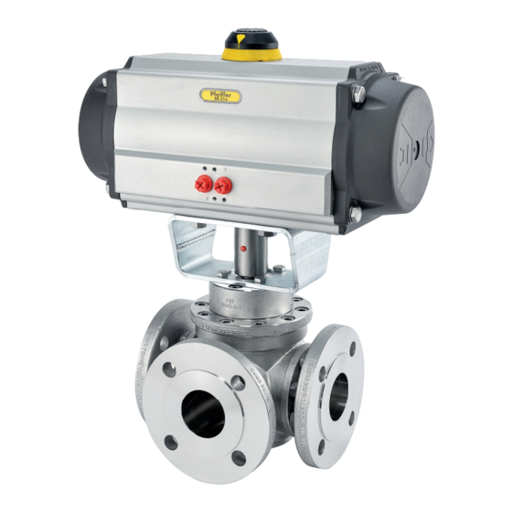
Multi-way ball valve BR 26l, BR 26t, BR 26v and BR 26x
Horizontal and vertical in DIN and ANSI versions
to combine with actuators
February 2024 edition
PFEIFFER Chemie-Armaturenbau GmbH · Hooghe Weg 41 · 47906 Kempen · Germany
Phone: +49 2152 2005-0 · Fax: +49 2152 1580
sales-pfeiffer-de@samsongroup.com · www.pfeiffer-armaturen.com
Advertisement
Table of Contents

Related Manuals for Samson BR 26l


Summary of Contents for Samson BR 26l
- Page 1 MOUNTING AND OPERATING INSTRUCTIONS EB 26l Translation of the original manual Multi-way ball valve BR 26l, BR 26t, BR 26v and BR 26x Horizontal and vertical in DIN and ANSI versions to combine with actuators February 2024 edition PFEIFFER Chemie-Armaturenbau GmbH · Hooghe Weg 41 · 47906 Kempen · Germany Phone: +49 2152 2005-0 ·...
- Page 2 Note regarding this installation and operating manual This Installation and Operating Manual (EB) provides guidance for safe assembly and operation. The notes and instructions in this EB are binding when handling PFEIFFER devices. The fi gures and illustrations in this EB are ex- amples and must therefore be considered as such.
-
Page 3: Table Of Contents
Multi-way ball valve assembly 3.5.1 Assembly of the horizontal 3-way ball valve BR 26l / BR 26t, DN 15 to 32 and NPS½ to 1¼ 3.5.2 Assembly of the horizontal 3-way ball valve BR 26l / BR 26t, DN 40 to 200 and NPS1½ to 8 3.5.3... - Page 4 Content Start-up Operation Malfunction Detecting and rectifying errors Carrying out emergency measures Servicing Periodic tests Maintenance work 9.2.1 Replacing the seat rings and ball Ordering spare parts and consumables 10 Decommissioning 10-1 11 Removal 11-1 11.1 Removing the multy-way ball valve from the pipe 11-1 11.2 Disassembling the actuator...
-
Page 5: Safety Instructions And Safety Measures
Intended use relevant standards, are capable of evaluating the assigned The multi-way ball valve BR 26l, BR 26t, BR 26v and BR 26x are tasks and identifying possible hazards. manually operated in combination with an actuator for the regu- lation of the volume fl... -
Page 6: Notes Regarding Possible Severe Personnel Injury
Safety instructions and safety measures − An actuator unit that is subsequently installed on the ball DANGER valve is adapted to the ball valve and the max. torque is ob- served, and is correctly adjusted in the end positions, and in Hazards and damage due to unsuitable ball valves! particular in the opening position of the ball valve. -
Page 7: Notes Regarding Possible Property Damage
Safety instructions and safety measures 1.3 Notes regarding possible property WARNING damage Danger of injury due to preloaded springs! Ball valves that are equipped with preloaded actuator springs NOTE are under mechanical tension. Before working on the actuator, release the compression from Damage to the ball valve due to contamination! the preloaded springs, see the corresponding actuator docu- Contamination (e.g. -
Page 8: Warning Notes On The Device
Safety instructions and safety measures NOTE Damage to the ball valve due to unsuitable tools! Unsuitable tools can damage the ball valve. Suitable tools are required to work on the ball valve, see Chapter “15.1.3 Tools”. Damage to the ball valve due to unsuitable lubricants! Unsuitable lubricants can corrode and damage the surface. -
Page 9: Markings On The Device
Remark Manufacturer PFEIFFER Address see Chapter “15.3 Service” Valve type BR (and number value) e.g. BR 26l = Series 26l, see the PFEIFFER catalogue Body material e.g. 1.4408 Material standard according to DIN EN 10213-4 Size DN (and number value) Number value in [mm], e.g. -
Page 10: Type Plate
Markings on the device 2.1 Type plate 2.1.1 Actuator type plate See the corresponding actuator documentation. 2.2 Material identifi cation The ball valves are marked on the body with the material specifi - cation; see “Table 2-1: Marking on the type plate and on the body of the ball valve”. -
Page 11: Design And Principle Of Operation
Function and principle of operation The process medium can fl ow through the full port in the mul- ti-way ball valves of the BR 26l, BR 26t, BR 26v and BR 26x. They are primarily used to divide media in the piping system. -
Page 12: Additional Fi Ttings
Design and principle of operation 3.2 Additional fi ttings 3.5 Multi-way ball valve assembly The ball valves BR 26l, BR 26t, BR 26v and BR 26x are pro- Strainer duced with various designs so that they cannot be documented in PFEIFFER recommends installing a strainer in front of the ball one construction manual. - Page 13 Design and principle of operation Seat ring soft seal version, not spring-loaded Further assembly for all versions Insert the seat ring (7) into the respective body chamber of Insert the sealing (10) into the corresponding recesses in the the two body fl anges (2). outlet fl...
- Page 14 Sectional drawing of the horizontal 3-way ball valves BR 26l and BR 26t, DN 15 ... 32 and NPS½ ... 1¼ Table 3-1: Parts list of the horizontal 3-way ball valves BR 26l and BR 26t, DN 15 ... 32 and NPS½ ... 1¼...
- Page 15 (28) in the main body. 3.5.2 Assembly of the horizontal 3-way ball valve BR 26l / BR 26t, DN 40 to 200 and NPS1½ to 8 3.5.2.3 Pre-assembly of the packing bush Push the bearing bush (12) with a slight rotary movement on- 3.5.2.1 Pre-assembly of the body fl...
- Page 16 Sectional drawing of the horizontal 3-way ball valves BR 26l and BR 26t, DN 40 ... 200 and NPS1½ ... 8 Table 3-2: Parts list of the horizontal 3-way ball valves BR 26l and BR 26t, DN 40 ... 200 and NPS1½ ... 8...
-
Page 17: Assembly Of The Vertical 3-Way Ball Valve Br 26V, Dn 15 To 32 And Nps½ To 1¼
Design and principle of operation Place the disk spring set (13) over the control shaft (5) up to Info the V-ring packing (14). For the arrangement of the disk Only tighten the screws or nuts hand-tight; fi nal assembly is car- springs, see Fig. - Page 18 Design and principle of operation Further assembly for all versions Slightly rotate the V-ring packing (14) so it can be pushed over the mounted control shaft (5) more easily and insert it at Insert the sealing (9) into the corresponding recesses in the the appropriate packing location into the main body (1).
- Page 19 Design and principle of operation Fig. 3-4: Sectional drawing of the vertical 3-way ball valves BR 26v, DN 15 ... 32 and NPS½ ... 1¼ Table 3-3: Parts list of the vertical 3-way ball valves BR 26v, DN 15 ... 32 and NPS½ ... 1¼ Item Description Item...
-
Page 20: Assembly Of The Vertical 3-Way Ball Valve Br 26V, Dn 40 To 200 And Nps1½ To
Design and principle of operation Insert the sealing (9) into the corresponding recesses in the Info body fl ange (2). − For permissible torque for tightening the body fl anges and the stuffi ng box fl ange, see Table 15-1 and Table 15-3 in Chapter “15.1.1 Tightening torques”. - Page 21 Design and principle of operation Fig. 3-5: Sectional drawing of the vertical 3-way ball valves BR 26v, DN 40 ... 200 and NPS1½ ... 8 Table 3-4: Parts list of the vertical 3-way ball valves BR 26v, DN 40 ... 200 and NPS1½ ... 8 Item Description Item...
-
Page 22: Assembly Of The Horizontal 4-Way Ball Valve Br 26X, Dn 15 To 32 And Nps½ To 1¼
Design and principle of operation To complete the assembly, align the body fl anges (2) and the 3.5.4.5 Final assembly of the main body stuffi ng box fl ange (6). The body fl ange (2) (page C) pre-assembled in chapter 3.5.4.2 Tighten all screws or nuts evenly in alternating pattern. - Page 23 Design and principle of operation Fig. 3-6: Sectional drawing of the horizontal 4-way ball valves BR 26x, DN 15 ... 32 and NPS½ ... 1¼ Table 3-5: Parts list of the horizontal 4-way ball valves BR 26x, DN 15 ... 32 and NPS½ ... 1¼ Item Description Item...
- Page 24 Design and principle of operation Place the disc springs (13) onto the packing. For the arrange- 3.5.5.2 Pre-assembly of the outlet fl anges ment of the disc springs, see Fig. 3-6. (C and D) Press the bearing bush (11) into the packing box fl ange (6). Place both outlet fl...
-
Page 25: Assembly Of The Horizontal 4-Way Ball Valve Br 26X, Dn 40 To 200 And Nps1½ To
Design and principle of operation Carefully insert the ball (4) into the main body. Insert the low- 3.5.6 Assembly of the horizontal 4-way ball er trunnion of the ball into the bearing bush (28) in the main valve BR 26x, DN 40 to 200 and body. - Page 26 Design and principle of operation Fig. 3-7: Sectional drawing of the horizontal 4-way ball valves BR 26x, DN 40 ... 200 and NPS1½ ... 8 Table 3-6: Parts list of the horizontal 4-way ball valves BR 26x, DN 40 ... 200 and NPS1½ ... 8 Item Description Item...
-
Page 27: Assembly Of The 5/4-Way Ball Valve Br 26X, Dn 25 To 32 And Nps1 To 1¼
Design and principle of operation Rotate the bonnet fl ange (23) until the bores of both compo- Seat ring soft seal version, spring-loaded on all sides nents are aligned with each other. Place the disc spring jacket (22) on the disc spring (21). After applying grease to the screws (29) both parts are screwed together, evenly and in alternating pattern. - Page 28 Design and principle of operation Fig. 3-8: Sectional drawing of the 5/4-way ball valves BR 26x, DN 25 ... 32 and NPS½ ... 1¼ Table 3-7: Parts list of the 5/4-way ball valves BR 26x, DN 25 ... 32 and NPS½ ... 1¼ Item Description Item...
-
Page 29: Assembly Of The 5/4-Way Ball Valve Br 26X, Dn 40 To 200 And Nps1½ To
Design and principle of operation The body fl anges (2) pre-assembled in chapter 3.5.7.1 (side A 3.5.7.3 Assembly of the main body and B) are placed on the main body (1) one after the other and Place the main body (1) on an even and clean work surface, adjusted with the nuts (16). - Page 30 Design and principle of operation Insert the jacketed disc spring (21) into the body chambers in Place the disk spring set (13) over the control shaft (5) up to the four body fl anges (2). the V-ring packing (14). For the arrangement of the disk springs, see Fig.
- Page 31 Design and principle of operation Fig. 3-9: Sectional drawing of the 5/4-way ball valves BR 26x, DN 40 ... 200 and NPS1½ ... 8 Table 3-8: Parts list of the 5/4-way ball valves BR 26x, DN 40 ... 200 and NPS1½ ... 8 Item Description Item...
- Page 32 Design and principle of operation 3.5.8.6 Assembly of the ball valve Turn the main body for further installation so that all four mounting sides (A, B, C and D) are easy to reach. The bodys fl anges (2) pre-assembled in chapter 3.5.8.1 (side A, B, C and D) are placed on the main body (1) one after the other and adjusted with the nuts (16).
-
Page 33: Shipment And On-Site Transport
Shipment and on-site transport Shipment and on-site transport WARNING The work described in this chapter may only be performed by Danger of injury due to the tipping of the ball valve! specialist personnel qualifi ed to perform the corresponding task. Observe the centre of gravity of the ball valve. -
Page 34: Lifting Points On The Body
Shipment and on-site transport Fig. 4-1: Lifting points on the ball valve Secure the sling against shifting and slipping off. 4.3.3 Lifting points on the body Fasten the sling such that it can be removed again after in- Fasten a lifting sling to each fl ange of the housing and on the stallation in the pipe. -
Page 35: Storing The Multi-Way Ball Valve
Shipment and on-site transport Move the ball valve at a constant speed to the installation site. Install the ball valve in the pipe, see chapter 5.4 After installation in the pipe: check that the fl anges are fi rmly tightened and that the ball valve holds in the pipe. Remove the lifting slings. - Page 36 Shipment and on-site transport EB 26l_EN February 2024 edition Subject to technical changes...
-
Page 37: Installation
Installation When connecting the attachments, make sure that they can Installation be accessed from the operator level safely and easily. The work described in this chapter may only be performed by specialist personnel qualifi ed to perform the corresponding task. The following instructions apply additionally for ball valves. -
Page 38: Installing The Multi-Way Ball Valve In The Pipe
Installation Handle the ball valve with care and observe the instructions WARNING for the fl ange connection. Danger and damage due to high external loads on an actuator The counterfl anges must have smooth sealing surfaces. Other unit! shapes must be agreed upon with PFEIFFER. Actuators are not “stepladders”. -
Page 39: Installing The Multi-Port Ball Valve
Installation Fig. 5-6: Horizontal 4-way ball valve BR 26x with double L-Port Fig. 5-2: Horizontal 3-way ball valve BR 26l Fig. 5-7: Horizontal 5/4-way ball valve BR 26x Top view = actuator at the top Fig. 5-3: Horizontal 3-way ball valve BR 26t... -
Page 40: Checking The Assembled Ball Valve
Installation Screw the pipe together with the ball valve without tension. The ball valve must close and open correctly according to the control commands. Detected malfunctions must be fi xed be- fore commissioning, see Chapter “8 Malfunction”. NOTE Damage to the sealing surfaces and seals or untight fl ange WARNING connection due to improper assembly! Tighten the fl... -
Page 41: Start-Up
Start-up Commissioning/recommissioning Start-up − Open the ball valves slowly in the pipe. Opening slowly pre- The work described in this chapter may only be performed by vents a sudden increase in pressure and a resulting high fl ow specialist personnel qualifi ed to perform the corresponding task. speed that damages the ball valve. - Page 42 Start-up EB 26l_EN February 2024 edition Subject to technical changes...
-
Page 43: Operation
Operation − For the manual operation or manual override of the actuator Operation (if present), normal manual forces are suffi cient and the use As soon as the commissioning/recommissioning work is com- of extensions to increase the actuation torque is not permit- plete, see Chapter “6 Commissioning”, the ball valve is ready for ted. - Page 44 Operation EB 26l_EN February 2024 edition Subject to technical changes...
-
Page 45: Malfunction
Malfunction Malfunction When rectifying the malfunction, chapter “1 Safety instructions and safety measures” must be observed. 8.1 Detecting and rectifying errors Type of fault Possible cause Measures Leaks in the pipe connection The fl ange connection of the Tighten the fl ange screws. ball valve is leaky NOTE An excessive tightening torque when retightening the fl... -
Page 46: Carrying Out Emergency Measures
Malfunction Type of fault Possible cause Measures Problems in the actuator unit The pneumatic actuator must Disconnect the connection to the control pressure. be removed Remove the actuator from the ball valve (observe the “Safety instructions and safety measures”, see the included actuator unit manuals). -
Page 47: Servicing
Servicing Servicing NOTE The work described in this chapter may only be performed by Damage to the ball valve due to excessively high or low tight- specialist personnel qualifi ed to perform the corresponding task. ening torques! The following documents are required in addition for the mainte- The ball valve components must be tightened with specifi... -
Page 48: Maintenance Work
Servicing Measures in the case of a negative Test test result Check the rotary movement of If the actuator- and control shaft are the actuator- and control shaft blocked, remove the blockage. for smooth movement. WARNING! If the actuator- and control shaft are blocked (e.g. -
Page 49: Decommissioning
Decommissioning To decommission the ball valve for maintenance and repair work 10 Decommissioning or for disassembly, perform the following steps: The work described in this chapter may only be performed by Close the valves upstream and downstream of the ball valve specialist personnel qualifi... - Page 50 Decommissioning EB 26l_EN 10-2 February 2024 edition Subject to technical changes...
-
Page 51: Removal
Removal 11 Removal WARNING The work described in this chapter may only be performed by If a used valve is sent to PFEIFFER for service: specialist personnel qualifi ed to perform the corresponding task. Decontaminate the valves properly in advance. WARNING Danger of burning due to hot or cold components and pipe! When returning a used valve, include the safety data sheet... - Page 52 Removal EB 26l_EN 11-2 February 2024 edition Subject to technical changes...
-
Page 53: Repairs
Repairs 12 Repairs 12.2.1 Disassembly of the multi-port ball valve, DN 15 to 32 and NPS½ to 1¼ If the operation of the ball valve is no longer compliant or if it does not work at all, it is defective and must be repaired or re- Version of the ball valve, see Fig. - Page 54 Repairs Fig. 12-1: Multi-port ball valve DN 15 to 32 and NPS½ to 1¼ EB 26l_EN 12-2 February 2024 edition Subject to technical changes...
- Page 55 Repairs Fig. 12-2: Multi-way ball valve DN 40 to 200 and NPS1½ to 8 EB 26l_EN 12-3 February 2024 edition Subject to technical changes...
-
Page 56: Additional Repairs
Repairs Table 12-1: List of parts Item Description Item Description Main body Body fl ange Stud bolt / Screw Outlet fl ange Ball Screw Control shaft O-ring Stuffi ng box fl ange Disc spring Seat ring Disc spring jacket Counter bearing Bonnet fl... -
Page 57: Disposal
Disposal 13 Disposal For disposal, observe the local, national and international regulations. Do not dispose of old components, lubricant and hazardous materials with domestic waste. EB 26l_EN 13-1 February 2024 edition Subject to technical changes... - Page 58 Disposal EB 26l_EN 13-2 February 2024 edition Subject to technical changes...
-
Page 59: Certifi Cates
− Declaration of conformity for completed machinery accord- ing to Machinery Directive 2006/42/EC for the ball valve BR 26l, BR 26t, BR 26v and BR 26x, see page 14-4. − Declaration of conformity for partly completed machinery ac- cording to Machinery Directive 2006/42/EC for ball valve BR 26l, BR 26t, BR 26v and BR 26x, see page 14-5. - Page 60 Certifi cates EB 26l_EN 14-2 February 2024 edition Subject to technical changes...
- Page 61 Certifi cates EB 26l_EN 14-3 February 2024 edition Subject to technical changes...
- Page 62 Certifi cates EB 26l_EN 14-4 February 2024 edition Subject to technical changes...
- Page 63 Certifi cates EB 26l_EN 14-5 February 2024 edition Subject to technical changes...
- Page 64 Certifi cates EB 26l_EN 14-6 February 2024 edition Subject to technical changes...
-
Page 65: Annex
Annex 15 Annex ANSI Thread Tightening Qty. (15) torque class 183 Nm 15.1 Tightening torques, lubricant and tools 183 Nm 183 Nm 15.1.1 Tightening torques 183 Nm On request Info The tightening torques stated in the tables can only be under- stood as very rough and non-binding guide values and refer to a coeffi... - Page 66 Annex ANSI ANSI Thread Tightening Thread Tightening Qty. Qty. (19) torque 1) 2) (29) torque class class 44 Nm 74 Nm 74 Nm 74 Nm 44 Nm 183 Nm 1½ On request 183 Nm On request 183 Nm 44 Nm 183 Nm 44 Nm On request...
-
Page 67: Lubricant
Annex Table 15-6: Sealing unit A 15.2 Spare parts Seal Nominal pressure Description PFEIFFER recommends spare part sets for “Commissioning” and PN 10 to PN 25 Without inner eyelet for “2-year operation”, see Chapter: Flat seal PN 40 With inner eyelet −... -
Page 68: Spare Parts Of The Multi-Way Ball Valve Dn 15 Bis 32 And Nps½ Bis 1¼
Annex 15.2.1 Spare parts of the multi-way ball valve DN 15 bis 32 and NPS½ bis 1¼ Fig. 15-1: Exploded drawing of the multi-way ball valve DN 15 to 32 and NPS½ to 1¼ EB 26l_EN 15-4 February 2024 edition Subject to technical changes... - Page 69 Annex Table 15-9: Part list of the multi-way ball valve DN 15 to 32 and NPS½ to 1¼ Qty. Spare part kit BR 26l BR 26t BR 26v BR 26x Item Description Material Horizontal Horizontal Vertical Horizontal Commis- 2-year 5/4-way...
-
Page 70: Spare Parts Of The Multi-Way Ball Valve Dn 40 Bis 200 And Nps1½ Bis
Annex 15.2.2 Spare parts of the multi-way ball valve DN 40 bis 200 and NPS1½ bis 8 Fig. 15-2: Exploded drawing of the multi-way ball valve DN 40 to 200 and NPS1½ to 8 EB 26l_EN 15-6 February 2024 edition Subject to technical changes... - Page 71 Annex Table 15-10: Part list of the multi-way ball valve DN 40 to 200 and NPS1½ to 8 Qty. Spare part kit BR 26l BR 26t BR 26v BR 26x Item Description Material Horizontal Horizontal Vertical Horizontal Commis- 2-year 5/4-way...
-
Page 72: Service
Annex 15.3 Service For maintenance and repair work as well as malfunctions or de- fects, contact the After Sales Service at PFEIFFER for support. E-mail The After Sales Service can be reached at the e-mail address “sales-pfeiffer-de@samsongroup.com”. Necessary data Provide the following information in the case of questions and for troubleshooting: −... - Page 73 EB 26l_EN February 2024 edition Subject to technical changes...
- Page 74 EB 26l_EN February 2024 edition Subject to technical changes...
- Page 75 EB 26l_EN February 2024 edition Subject to technical changes...
- Page 76 PFEIFFER Chemie-Armaturenbau GmbH Hooghe Weg 41 · 47906 Kempen · Germany Phone: +49 2152 2005-0 · Fax: +49 2152 1580 E-Mail: sales-pfeiffer-de@samsongroup.com · Internet: www.pfeiffer-armaturen.com EB 26l_EN February 2024 edition Subject to technical changes...
Need help?
Do you have a question about the BR 26l and is the answer not in the manual?
Questions and answers