Advertisement
Quick Links
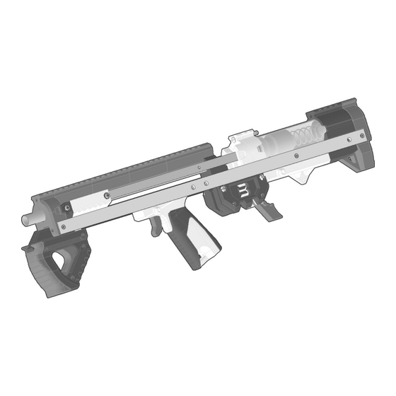
TALON CLAW Bullpup ASSEMBLY
The Talon Claw U is a Mag-Fed Pump-Action Homemade Nerf Blaster design for half-length darts ONLY released as a CC-
You are welcome to and encouraged to modify the files in any way you want. The Majority of the parts can be printed
with infill as low as 20% in PLA, but I would recommend printing in layers of 300 Micron or smaller. I would recommend
Hardware blaster kits are available for sale as made-to-order items. I'm producing these myself in what remains of my
DO NOT STORE IN TEMPERATURES ABOVE 100F. Storing the blaster inside of a car in warmer months will
cause the printed parts to distort or warp beyond their intended shape. If you have to store one in a vehicle,
DO NOT use this blaster for indoor wars or wars involving very short distances. The muzzle velocities this
design can reach are between 150fps and 210fps depending upon the darts used and the spring installed. If
indoor use is intended, obtain the lower fps springs that are currently available for this design (K31 and 788)
NC license file set by Captain Slug (http://www.captainslug.com).
a minimum of 1.5mm walls/perimeters for every part.
https://www.etsy.com/shop/CaptainSlug
free time.
store it in the trunk.
and use them.
Advertisement

Subscribe to Our Youtube Channel
Related Manuals for Captain Slug TALON CLAW U Bullpup


Summary of Contents for Captain Slug TALON CLAW U Bullpup
- Page 1 The Talon Claw U is a Mag-Fed Pump-Action Homemade Nerf Blaster design for half-length darts ONLY released as a CC- NC license file set by Captain Slug (http://www.captainslug.com). You are welcome to and encouraged to modify the files in any way you want. The Majority of the parts can be printed with infill as low as 20% in PLA, but I would recommend printing in layers of 300 Micron or smaller.
- Page 2 For most of the above hardware list the quantities are the MINIMUM required for assembly. Easily-lost items will have several spares and I typically include extras of the majority of the items. To assemble this blaster you will need a Slotted Screwdriver, Small Philips Screwdriver, 3/8 Combination Wrench, and a Round Needle File.
- Page 3 Above is a list of every printed part needed to assemble this blaster. The majority of the through holes should print to the required tolerance, but you will likely have one or two that may require minimal filing. Also make sure to trim off any burrs or oversized edges.
- Page 4 Use a slotted scredriver or allen key to push a 4-40 standoff into the socket from the middle of the Coupler print. Drive a 4-40 screw into the hole perpendicular to the standoff until it retains the standoff. Repeat for the opposite side. Add a hex nut to the end of a long 10-32 screw.
- Page 5 Use a slotted scredriver or allen key to push a 4-40 standoff into the socket from the middle of the Buttplate print. Drive a 4-40 screw into the hole perpendicular to the standoff until it retains the standoff. Repeat for the opposite side. Screw a hex nut onto the end of a long 10-32 screw, and use it to push the hex nut into the socket in the front of the Buttplate print.
- Page 6 Feed a long 10-32 screw through the upper hole in Magback and Pcap prints. Add a hex nut to the end of the screw, then tighten until the hex nut it drawn into the socket. Drive the screw until the hex nut bottoms out and the two parts are held tightly together.
- Page 7 Add a hex nut to the socket inside the barrel hole of the Magfront print. Drive a short 10-32 screw into it from underneath until the end of the screw is flush with the opposite side of the hex nut. Use a hammer to tap a hex nut into each socket in one of the nameplate prints.
- Page 8 Line up the remaining nameplate print and drive two long 10-32 screws through the assembly and into the hex nuts retained on the opposite side. Drive another 4-40 screw into the magfront print. Slide the Trelease and Krelease prints into the assembly until the holes in both line up with the holes in the assembly.
- Page 9 Slide a short pin through all of the parts until the release prints are retained. If the short pin will not feed through all of the parts you may need to remove the release prints and clean out the holes in them using a 3/32”...
- Page 10 Hook the loop of an extension spring onto the peg of the Sear print, then fish the spring in through the inside of the Mframe print. Hook the free end onto the 4-40 screw. Insert the round 4-40 standoff into the hole in the Sear print. Tilt the Sear print down until the standoff lines up with the through hole in the Mframe print.
- Page 11 Line the hole in the TriggerD print up with the holes in the Mframe print. Drive a short pin through both parts until centered. Drive a 4-40 screw into each side to retain the short pin. Push a u-channel onto the right side of the assembly, lining up the hole in it with the hole in the side of the Mframe print.
- Page 12 Push the Ramrod Core into the RamBase print, then secure it with a 4-40 screws from each side. DO NOT OVERTIGHTEN. Add an o-ring to the undercut in the RamBase print, then add the adhesive-backed Shockpad to the back face of the RamBase print.
- Page 13 Add an o-ring to the undercut of the Plunger/Piston print. Slide it into the lubricated end of the plunger tube. Slide the ramrod assembly all the way forward in the magwell assembly. Push the Sear out of the way by hand, then slide the plunger tube onto the base of the ramrod until the plunger tube bottoms out against the inside of the magwell assembly.
- Page 14 Slide the foregrip assembly onto the bolt arms. Secure it with four short 10-32 screws. Secure the Muzzle print to the end of the u-channel with a 4-40 screw. Slide the foregrip back a few inches as shown. Slide the barrel in through the Muzzle and Magfront prints until it is flush with the back of the Magfront print. Tighten both indicated screws to clamp the barrel into place.
- Page 15 (If included) Line the BPrailD print up with the hole in the top of the Magfront print. Then secure it by driving a 4-40 screw through both parts. Add a hex nut to the slot in the BPrailD print Slide the three OGrail prints inbetween the Muzzle and BPrailD prints Drive a 13-inch threaded rod through all of the parts and then into the hex nut.
- Page 16 Force a long 10-32 screw into the hole inside the GripF print. Slide the ARgrip print onto the end of the screw, and over the boss of the GripF print. Add a hex nut to the end of the long 10-32 screw, then use a slotted screwdriver to tighten the screw until it draws the hex nut into the socket of the ARgrip print.
- Page 17 Force a short pin through the holes in both parts. Then retain it from each side by driving a 4-40 screw into the GripF print. Push the GripF assembly into the u-channel ahead of the Magwell. Some sanding, filing, or trimming of the print may be needed for a nice fit between the parts.
- Page 18 Slide the slots in the Triglink prints onto the pegs of the Trigger and Trigger D prints. You will need to pull one or both pegs by hand a little in order for them to line up with the slots. Carefully slide the remaining u-channel onto the left side of the blaster over the Triglink prints until it bottoms out againgst the whole assembly.
- Page 19 Slide the coupler print into the u-channels, then onto the plunger tube until flush. Secure with a 4-40 screw on each side. Add a hex nut to the slot in the top of the coupler print. Slide the main spring into through the coupler, into the plunger tube, and then into the back of the plunger/piston.
- Page 20 Insert a magazine into the magwell. If the fit is too tight you may need to loosen the screw that clamps the barrel into the muzzle, then the two that attach the front of the NamePlate prints to the MagFront print. Then retighten once the magazine fit feels correct.
Need help?
Do you have a question about the TALON CLAW U Bullpup and is the answer not in the manual?
Questions and answers