Advertisement
Quick Links
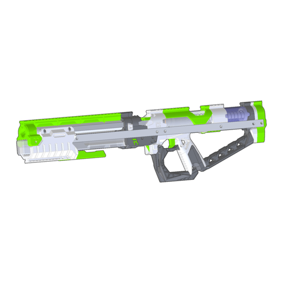
RIVALBURN3 ASSEMBLY INSTRUCTIONS
The Rivalburn 3 is a Mag-Fed Pump-Action Homemade Nerf Blaster design released as a CC-NC license file set by Captain
Slug (http://www.captainslug.com).
You are welcome to and encouraged to modify the files in any way you want. The Majority of the parts can be printed
with infill as low as 20% in PLA, but I would recommend printing in layers of 300 Micron or smaller. I would recommend
a minimum of 1.5mm walls/perimeters for every part.
Hardware kits and Full Blasters are available for sale as made-to-order items. I'm producing these myself in what
remains of my free time.
https://www.etsy.com/shop/CaptainSlug
DO NOT STORE IN TEMPERATURES ABOVE 100F. Storing the blaster inside of a car in warmer months will
cause the printed parts to distort or warp beyond their intended shape. If you have to store one in a vehicle,
store it in the trunk.
DO NOT use this blaster for indoor wars or wars involving very short distances. The muzzle velocities this
design can reach are between 150fps and 210fps depending upon the darts used and the spring installed. If
indoor use is intended, obtain the lower fps springs that are currently available for this design (K31 and 788)
and use them.
Advertisement

Related Manuals for Captain Slug RIVALBURN3


Summary of Contents for Captain Slug RIVALBURN3
- Page 1 RIVALBURN3 ASSEMBLY INSTRUCTIONS The Rivalburn 3 is a Mag-Fed Pump-Action Homemade Nerf Blaster design released as a CC-NC license file set by Captain Slug (http://www.captainslug.com). You are welcome to and encouraged to modify the files in any way you want. The Majority of the parts can be printed with infill as low as 20% in PLA, but I would recommend printing in layers of 300 Micron or smaller.
- Page 2 For most of the above hardware list the quantities are the MINIMUM required for assembly. Easily-lost items will have several spares and I typically include extras of the majority of the items. To assemble this blaster you will need a Slotted Screwdriver, Small Philips Screwdriver, Scissors, 3/8” Combination Wrench, and maybe a Small Round Needle File.
- Page 3 Above is a list of every printed part needed to assemble this blaster. The majority of the through holes should print to the required tolerance, but you will likely have one or two that may require minimal filing. Also make sure to trim off any burrs or oversized edges.
- Page 4 Duplicate the same steps used on the Frontbutt print to add two hex standoffs to the sockets in the Coupler print. Place a 10-32 hex nut onto the end of a 1-3/4” length screw, then push the hex nut into the front of the spring guide of BackButt until it bottoms out.
- Page 5 Line up the hole in the Elevator print with the holes in the MagBack sides and drive a 4-40 screw in from each side. Tie a knot into one end of the 3/32” elastic and feed it through the hole in the front of the Elevator print, then in through the hole in the middle of the Magback print.
- Page 6 Hook an extension spring onto the peg on the Sear print, and then use the Sear print to fish the spring down into the Grip print. Connect the available opposite loop on the spring onto the hook inside the Grip print. Insert the round standoff into the hole in the middle of the Sear, and then slide it into the Grip until it lines up with the hole in the Grip print.
- Page 7 Sandwich the resulting assembly with the u-channel pair. Move the elastic cord at the front of the assembly out of the way so that you can slide the barrel into the front. Then slide the Foregrip print over the u-channel pair. Slide the Muzzle print onto the u-channel pair, and over the barrel.
- Page 8 Push a hex nut into the slot in the top of the Magfront assembly, then feed the 13” length threaded rod through the muzzle, through all of the rail segment prints, and then into the front of the hex nut. Drive the threaded rod into the hex nut, leaving roughly ½”...
- Page 9 Slide the Prong print into the slot in the Foregrip print so that the holes in both are lined up. Secure using two or four 4-40 screws. Secure the bolt arms to the ramrod using two 4-40 screws. Add an o-ring to the undercut on the ramrod base. Then peel of the backing from the shockpad and adhere it to the back of the ramrod base.
- Page 10 Force the plunger tube over the ramrod base and into the back of the Magback print until it bottoms out. You may need to use a hammer to lightly tap it until seated. Add an o-ring to the undercut on the Plunger print, and then feed the plunger into the plunger tube. Slide the grip assembly into the u-channel pair.
- Page 11 The following steps are optional. Wedge a printed lower stock spacer or spacer tubing between the heel of the Grip assembly and the lower tang of the Frontbutt print. Insert a hex nut into the slot in the (optional) Grip insert if present. Add a hex nut to one end of the 8.25”...
- Page 12 Insert a magazine into the front of the blaster until the detent latches. This can be done whenever desired regardless of the breech being open or closed. To remove the magazine, pull up on both sides of the MagDetent and push the mag from the exposed portion of it that is behind the foregrip.
Need help?
Do you have a question about the RIVALBURN3 and is the answer not in the manual?
Questions and answers