Advertisement
Quick Links
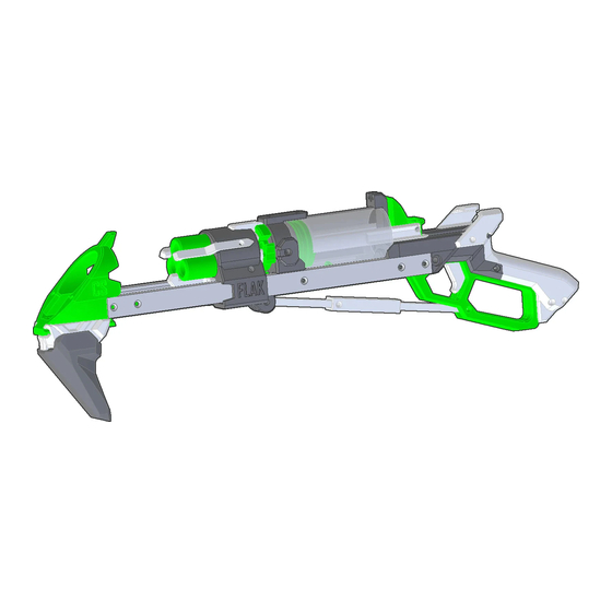
FLAK ASSEMBLY INSTRUCTIONS
The FLAK is a multi-ammo Lever-Action spring-plunger homemade blaster powered by elastic cords. It can be setup to
accept and fire from Rival Mags, Talon Mags, Sledgefire Shells, Spring Thunder Shells, Trilogy Shells, spigot-launched
Missiles (Demolisher Rockets), and anything you want to plug onto a 1/2 SCH40 pipe spigot. It is released as a Non-
Commercial license file set by Captain Slug (http://www.captainslug.com).
You are welcome to and encouraged to modify the files in any way you want. All of the parts can be printed with infill as
low as 20% in PLA, but I would recommend printing in layers of 200 Micron or smaller. Also set the wall/perimeters to
Hardware kits and Blaster kits are available for sale. I'm producing these myself in what remains of my free time.
DO NOT STORE IN TEMPERATURES ABOVE 100F. Storing the blaster inside of a car in warmer months will
cause the printed parts to distort or warp beyond their intended shape. If you need to store one in a vehicle
DO NOT aim this blaster at faces. The muzzle velocities this design can reach are between 80fps and 150fps
For most of the above hardware list the quantities are the MINIMUM required for assembly. Easily-lost items will have
several spares and I typically include extras of the majority of the items. Item #19 is not used in this build.
To assemble this blaster you will need a Small Philips Screwdriver, Flat screwdriver, Scissors, and a Round Needle File.
The Plunger Tube in the Hardware Kit does come pre-lubricated. But it's also a good idea to have extra lubricant on-hand
for the Plunger Tube and I would recommend only using a clear Silicone Grease such as Oatey's brand #30219. Any clear
90% silicone grease will work fine so long as it does not include any additives. NEVER USE SILICONE LUBRICANT FROM
AN AEROSOL CAN. The propellants used in those are harmful to plastic parts.
1.5mm to 2mm thickness.
https://www.etsy.com/shop/CaptainSlug
temporarily, store it in the trunk.
depending upon the darts used and the bands installed.
Advertisement

Related Manuals for Captain Slug FLAK


Summary of Contents for Captain Slug FLAK
- Page 1 FLAK ASSEMBLY INSTRUCTIONS The FLAK is a multi-ammo Lever-Action spring-plunger homemade blaster powered by elastic cords. It can be setup to accept and fire from Rival Mags, Talon Mags, Sledgefire Shells, Spring Thunder Shells, Trilogy Shells, spigot-launched Missiles (Demolisher Rockets), and anything you want to plug onto a 1/2 SCH40 pipe spigot. It is released as a Non- Commercial license file set by Captain Slug (http://www.captainslug.com).
- Page 2 Above is a list of every printed part needed to assemble this blaster. The majority of the through holes should print to the required tolerance, but you will likely have one or two that may require minimal filing. Also make sure to trim off any burrs or oversized edges.
- Page 3 Force a Hex Standoff into the two sockets in the Sideplate print. Drive a 4-40 screw into them from the opposite side. Keep driving the 4-40 screw until the standoffs can no longer be seen through the perpendicular holes at the bottom edge of the print.
- Page 4 A. Once the perpendicular holes where shown are unobstructed by the hex standoffs, drive a 4-40 screw into each. These screws will retain the standoffs and prevent them from backing out of the sockets. B. Remove the 4-40 screws that were used to pull the standoffs into the bottom of the sockets. C.
- Page 5 A. Force a Hex Standoff into the two sockets in the bottom inside of the Muzzle print. B. Drive a 4-40 screw into them from the opposite side. Keep driving the 4-40 screw until the standoffs can no longer be seen through the perpendicular holes at the bottom edge of the print.
- Page 6 Insert a round standoff into the hole in the Sear print, then line the two up with the holes in the Grip print. Secure the round standoff in the Grip print with two 4-40 screws. Slide the Trigger print into the Grip print so that the “heel” is resting inside. Tie the end of the smaller size elastic and then feed it through the holes at the front of the Sear and Trigger prints.
- Page 7 Slide the Lever prints into the grip until the large hole lines up with the large holes in the Trigger and Sideplate prints. Feed a long 10-32 screw in through the Sideplates, Lever, and Trigger prints. Drive a 4-40 screw in through the perpendicular hole in the Sideplate print until it clamps down onto the long 10-32 screw.
- Page 8 Attach the Center print to the front of the Sideplate prints using two 4-40 screws. Slide the Plunger assembly down over the grip assembly. Slide the plunger tube onto the end of the Plunger. Force the Cap print into the plunger tube until it bottoms out. Line up the holes in one of the U-channels with the Sideplate and Cap prints, and secure it with 4-40 screws.
- Page 9 Insert a short pin into each hole in the front of the Center print, then push the rail_max print onto the short pins. Secure the rail_max print to the Cap print using two 4-40 screws. The Rear Half Assembly is complete. Now onto the various ammo type front ends.
- Page 10 Inline RIVAL Magazine Assembly Attach the RamR Print to the front of the Cap print using two 4-40 screws. Tie a knot at the end of the 3/32” elastic, then feed the free end through the ClawR print and into the hole in the side of the CartRT print. Then feed the free end in the hole perpendicular to that inside hole and out the back of the CartRT print.
- Page 11 Line up the hole in the ReleaseR print with the hole in the front of the CartRT print, then drive a 4-40 screw in from each side. The ReleaseR print should rotate freely. Knot the end of a length of 3/32” elastic and feed it in through the hole in the top of the CartRT print, then in through the hole in the side of the ReleaseR print.
- Page 12 Repeat the above steps with the MuzzRT print, the n secure it to the exposed end of the barrel. Make sure to align the upper sight blade so that it is perfectly vertical. Drive a 4-40 screw into the small hole in the front of the MuzzRT print. This is the adjustable hop-up. If when testing the blaster later on and the Rival Rounds fired float upwards too much, this screw will need to be tightened further.
- Page 13 RIVAL Magazine Assembly Attach the RamR Print to the front of the Cap print using two 4-40 screws. Tie a knot at the end of the 3/32” elastic, then feed the free end through the ClawR print and into the hole in the side of the CartR print. Then feed the free end in the hole perpendicular to that inside hole and out the back of the CartR print.
- Page 14 Line up the hole in the ReleaseR print with the holes in the slot in the bottom of the CartR print. Drive a 4-40 screw in from both sides until they push into the hole in the ReleaseR print, retaining it. The ReleaseR print should still be able to rotate after both screws are installed.
- Page 15 Add a Hex nut to the socket inside the barrel hole of the MuzzR print, then drive a 10-32 screw into it from the hole underneath until it pulls it tightly into the socket. Back the screw out enough to allow the barrel to be inserted and bottomed out past the screw. Tighten the screw again until it clamps down onto the barrel.
- Page 16 Slide the Rival Assembly onto the U-channel pair. Line up the hole in the Linkage assembly with the holes in the slot in the front of the Lever Assembly. Drive a 4-40 screw in from both sides until they push into the hole in the Linkage assembly, retaining it. The Linkage assembly print should still be able to rotate after both screws are installed.
- Page 17 TALON Magazine Assembly Press the Ramrod core into the RamR print. Drive a 4-40 screw in from each side to retain it. These can be adjusted later to correct for vertical alignment relative to the barrel. Add an 012 o-ring to the undercut on the ramrod. Attach the Ramrod assembly to the front of the Cap print using two 4-40 screws.
- Page 18 Line up the hole in the ReleaseD print with the holes in the slot in the bottom of the CartD print. Drive a 4-40 screw in from both sides until they push into the hole in the ReleaseD print, retaining it. The ReleaseD print should still be able to rotate after both screws are installed.
- Page 19 Slide the Talon Mag assembly onto the U-channels. Line up the hole in the Linkage assembly with the holes in the slot in the front of the Lever Assembly. Drive a 4-40 screw in from both sides until they push into the hole in the Linkage assembly, retaining it. The Linkage assembly print should still be able to rotate after both screws are installed.
- Page 20 Slide the barrel in through the LipD print and then into the front of the CartD print. Back the screw in the hex nut at the front of the CartD print out enough to allow the barrel to be inserted until flush with the inside surface of the magazine well.
-
Page 21: Shell Assembly
Shell Assembly For the Trilogy shells feed each free end of some 3/32” elastic cord through the two holes in the ExtractorT print, then into the two matching holes in the RamS print. Feed them through until they come out the bottom side of the print. Tie a knot at one of the free ends, then pull up all of the slide from the remaining free end. - Page 22 For the Trilogy sell you will need to use four 4-40 screws to attach the Hook and HookT2 prints to the outside of the CartT print. Otherwise the rest of the steps are the same. Line up the hole in the EjectorS print with the holes in the Cart print and drive a 4-40 screw in from each side. The EjectorS print should rotate freely after the screws are bottomed out.
- Page 23 Line up the hole in the Linkage assembly with the holes in the slot in the back of the CartR print. Drive a 4-40 screw in from both sides until they push into the hole in the Linkage assembly, retaining it. The Linkage assembly print should still be able to rotate after both screws are installed.
- Page 24 Take one of the 1/8” diameter x 28” length elastic cords and tie a granny knot near the end and pull the knot as tight as possible. Feed the free end in through the slot in the middle of a “Cordpler” print, then pull the knot inside. Loop the free end back into the Cordpler print from the opposite side and out the slot.
- Page 25 Wrap the cross-over around the back of the plunger and over to the other side of the blaster. Secure the free end of the loop to the cleat on the other side of the Cap print. Repeat this with a second, third, and if desired a fourth main elastic loop. The 1/8”...
- Page 26 Keep driving the 4-40 screw until the standoffs can no longer be seen through the perpendicular hole in the side of the print. A. Once the perpendicular hole where shown is unobstructed by the hex standoff, drive a 4-40 screw into it the perpendicular hole.
Need help?
Do you have a question about the FLAK and is the answer not in the manual?
Questions and answers