
Related Manuals for Rinnai Infinity E16


Summary of Contents for Rinnai Infinity E16
- Page 1 MODELS: Infinity E16 (REU-E1620W-E) Infinity E24 (REU-E2426W-E) Instantaneous condensing water heaters Operation and installation manual...
- Page 2 REU-E1620W-E) E16 - ( REU-E2426W-E) E24 - ( 776829 Quality system standard ISO 9001 The design, development and manufacture of gas water heating appliances done under Rinnai’s quality management system is certified under the quality management system Standard ISO 9001.
-
Page 3: General Advice
Dear Customer, our compliments for having chosen a Rinnai top quality product, able to assure wellbeing and safety for a long period of time. As a Rinnai Customer you can also count on a qualified aftersales service to guarantee a constant efficiency of Your appliance. -
Page 4: Warranty Period
Replacement of the entire product or replacement of any parts may only be authorised by Rinnai. Rinnai does not authorise any person or company to assume for it any obligation or liability in connection with the replacement of a product or heat exchanger. If Rinnai determines that repair of a product is not possible, Rinnai will replace the product with a comparable product, at Rinnai’s discretion. -
Page 5: Table Of Contents
1.3 WATER TEMPERATURE CONTROL ..............................13 1.3.1 MAXIMUM DELIVERY TEMPERATURES ..........................13 1.3.2 OPERATION WITHOUT WATER CONTROLLERS ......................... 13 1.3.3 RINNAI WATER CONTROLLERS ............................... 13 1.3.4 WATER CONTROLLER COMBINATIONS & CONFIGURATIONS ..................14 1.3.5 UNIVERSAL WATER CONTROLLER (MC-601) OPERATION .................... 15 1.4 TROUBLE SHOOTING .................................... - Page 6 3. MAINTENANCE INSTRUCTIONS ................................34 3.1 PCB INTERFACE LAYOUT AND FUNCTIONS ..........................35 3.2 GAS CONVERSION AND PRESSURE ADJUSTMENT ........................36 3.3 DATA TRANSFER BETWEEN PCB’S ..............................37 3.4 WATER FLOW CHART .................................... 37 3.5 FLOW CHART ......................................38 3.6 WIRING DIAGRAM AND DIAGNOSTIC POINTS ........................... 39 3.7 MAINTENANCE ......................................
-
Page 7: User's Instructions
1. USER’S INSTRUCTIONS The following section provides instructions for proper use of the product. This section is intended for the use by qualified technical personnel and end users. -
Page 8: If You Smell Gas
The user must not use the appliance in any way that it was not meant to be used. The user may only use the heater as detailed in the User portion of this manual. Interference with a sealed component is not permitted. In case of defect parts only use genuine Rinnai components for replacement. -
Page 9: Features And Benefits
Congratulations on purchasing the latest technology temperature controlled Rinnai continuous flow water heating system. The Rinnai continuous flow water heater products NEVER RUN OUT of hot water. Whilst electricity, water and gas supplies are connected, hot water is available whenever hot water taps are open. -
Page 10: Important Safety Information
Do not modify this appliance. Do not attempt to repair, replace or open sealed parts or disassemble the appliance: improper adjustment, alteration, service or maintenance could significantly affect the safety of the product. Contact the Rinnai service if you detect any unusual condition. Use original parts to repair the appliance. -
Page 11: Operational Safety Information
Do not store flammable objects near the appliance: it could cause a product failure or fire. Do not spray aerosols in the vicinity of this appliance while it is in operation. Check that the appliance is supplied with the correct gas type and pressure according to the data plate: ensure that the gas in use matches with the gas indicated on the data plate. - Page 12 If water pipes are frozen, there would not be water flow in the system. Use a heat source (e.g. hair dryer) to unfreeze the frozen components and pipes. Before using the appliance after defrosting contact the Rinnai service to verify possible damages.
-
Page 13: Water Temperature Control
1.3.2 OPERATION WITHOUT WATER CONTROLLERS Rinnai continuous flow water heater products do not use a pilot light. When installed and operated, the opening of any hot water tap will automatically start the appliance. Once water is flowing through the appliance the burner will be ignited by electronic ignition. -
Page 14: Water Controller Combinations & Configurations
Water resistance The MC-601 universal water controller is a water resistant device, however excessive exposure to water such as immersion may result in damage to the water controller. Durability of water controllers is improved when positioned outside of the shower recess. Controllers must be installed at least 400 mm above the highest part of a sink, basin or bath. -
Page 15: Universal Water Controller (Mc-601) Operation
1.3.5 UNIVERSAL WATER CONTROLLER (MC-601) OPERATION WATE HEATE 'IN USE' INDICATO Indicates that a water heater is delivering hot water. DIGITAL MONITO Indicates the temperature selected. Error messages flash in event of a fault. °C TEMPE ATU E CONT OL BUTTONS CONTROLLE P IO ITY INDICATO Used to select water temperature. - Page 16 Lock function To prevent tampering and increase the safety level of the product, °C especially for children, it is possible to lock the control panel. To lock the panel it is necessary to press, and keep pressed for about five seconds, the ‘Priority’ keys and the key to increase the temperature (up arrow) (Fig.1).
-
Page 17: Trouble Shooting
1.4 TROUBLE SHOOTING Rinnai continuous flow water heaters have a self diagnostic capability. If a fault occurs, an error code will flash on the digital monitor of your water controllers. This assists with diagnosing the fault, and may enable you to overcome a problem without a service call. -
Page 18: Trouble Shooting Without Remote Control
Rinnai has a service and spare parts network with personnel who are fully trained and equipped to give the best service on your Rinnai appliance. If your appliance requires service, please call our national help line. - Page 19 If the information in this manual is not followed exactly a fire or explosion could result. This manual must be read in its entirety before installing the appliance. If you are unsure of any point contact Rinnai or your supplier.
-
Page 20: Installer's Instructions
2. INSTALLER’S INSTRUCTIONS The following section provides specific instructions for proper installation of the product. This section is intended for the use by qualified technical personnel. -
Page 21: Important Information
It is the installer’s responsibility to ensure that the unit has been installed to all current requirements. Please be sure that you are fully aware of your obligations and responsibilities under these regulations. In case of defective parts only use genuine Rinnai components for replacement failure to do so will invalidate any warranty. Disposal Information: Under the laws and local regulations, this product must be disposed separately from household waste. -
Page 22: Installation Warnings
The Rinnai Infinity is conceived as continuous flow water heater. The appliance is suitable for domestic use to produce hot water. The appliance must be power plugged, connected to the gas line, to the sanitary installation, and to a suitable discharge point to drain the condensate. -
Page 23: Unpacking The Water Heater
Prior to use make sure that the water heater is set up for the correct type of gas and that the appliance is intact. If the appliance is clearly damaged or you have doubts do not install the water heater and contact your supplier or Rinnai immediately for further information. Together with the appliance, in the packaging, you can find the following: (5x) Screws and wall plugs to fix the appliance... -
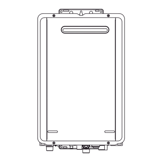
Page 24: Main Components
2.4 MAIN COMPONENTS Illustration varies depending on model. NAME NAME CASING ASS’Y GAS CONTROL ASS’Y FRONT PANEL ASS’Y WATER FLOW CONTROL DEVICE FLUE OUTLET GAS CONNECTION OVERHEAT SWITCH WATER FILTER ASS’Y HEAT EXCHANGER WATER INLET THERMAL FUSE NEUTRALISED DRAIN OUTLET FLAME ROD NEUTRALISER TANK DRAIN VALVE ELECTRODE... -
Page 25: General Scheme And Operation Principles
2.5 GENERAL SCHEME AND OPERATION PRINCIPLES *Only for REU-E2426W-E model. 2.5.1 OPERATION PRINCIPLES Ignition Press ON/OFF Button of Remote Controller to turn on unit and the remote controller display and priority LED will light up. When a hot water tap is opened the water flow Sensor revolves and sends a pulse signal to the printed circuit board (PCB). -
Page 26: Installation
The unit will operate at lower supply pressures but the maximum flow rate may not be achieved. Most installations will use high temperature setpoints which will reduce the available flow rate and heat exchanger pressure drop, and therefore less pressure will be required at the inlet. Contact Rinnai or your supplier for further instruction. -
Page 27: Gas Connection
III. The appliance is equipped with power cord and plug: if the cable has to be replaced contact qualified professionals and use original Rinnai parts only not to invalidate the warranty. Do not use adaptors, multiple socket or extension cords. -
Page 28: Appliance Location
2.6.6 APPLIANCE LOCATION The External appliance should be considered as a flue terminal. There is guidance below taken from BS5440 regarding positioning and distances however this is for guidenance only. The current standards should always be consulted before installtion incase any updates have been made to the standards, Symbol Terminal Position Dimensions... -
Page 29: Condensate Guidelines
2.6.7 CONDENSATE GUIDELINES To prevent condensate damage, follow these guidelines: • Do not plumb the condensate drain with the pressure relief valve; both must be plumbed independently to drain. • All condensate must drain and be disposed of according to local codes. •... -
Page 30: Water Control
• The FOURTH water controller in any installation must be an universal water controller. For more information regarding deluxe kitchen and bathroom water controllers, contact Rinnai or visit: www.rinnai.it. Location • Do not install water controllers near a heat source, such as a cook top, stove or oven. Heat, steam, smoke and hot oil may cause damage. -
Page 31: Universal Water Controller (Mc-601) Installation
2.7.2 UNIVERSAL WATER CONTROLLER (MC-601) INSTALLATION 1. Determine the most suitable position. 2. Mark and drill 3 holes (mounting and cable access) for water controller dimensions. Film Controller Cable Cover Plates Screws Connector Fig. 1 Fig. 2 Fig. 3 Fig. 4 3. -
Page 32: Commissioning
• After testing is completed, explain to the householder the functions and operation of the water heater and water controllers (if fitted). Remind the customer to complete the warranty card and forward to Rinnai. • Inform customer on use of an adequate water softening system to prevent damages to heat exchanger. -
Page 33: Benchmark Commissioning Sheet
GAS FIRED CONTINUOUS FLOW WATER HEATER COMMISSIONING CHECKLIST 2.9 BENCHMARK COMMISSIONING SHEET This Commissioning Checklist is to be completed in full by the competent person who commissioned the water heater as a means of demonstrating compliance with the appropriate Building Regulations and then handed to the customer to keep for future reference. Failure to install and commission according to the manufacturer’s instructions and complete this Benchmark Commissioning Checklist will invalidate the warranty. -
Page 34: Maintenance Instructions
3. MAINTENANCE INSTRUCTIONS The following section provides specific instructions for proper maintenance of the product. This section is intended for the use by qualified technical personnel. -
Page 35: Pcb Interface Layout And Functions
3.1 PCB INTERFACE LAYOUT AND FUNCTIONS Operation of the PCB interface To enter into the PCB’s programming mode press PB2 until Communication interface socket the LED digital display shows “1” (Gas type); the current set value of “menu 1” will be displayed shortly afterwards (the PB1 - Data transfer button: activates data transfer when PCB is replaced possible values of “menu 1”... -
Page 36: Gas Conversion And Pressure Adjustment
3.2 GAS CONVERSION AND PRESSURE ADJUSTMENT Only qualified professionals are authorized to carry out the operations described. The product warranty does not cover any alterations due to non-qualified personnel. IMPO TANT The min and max gas operating pressures are factory pre-set: under normal circumstances any adjustment is not required during installation. -
Page 37: Data Transfer Between Pcb's
3.3 DATA TRANSFER BETWEEN PCB’S If a new PCB needs replacing, you can transfer data (gas type, model type, gas pressure and error history) from the existing PCB to the new one by doing the following: 1. Check the current settings and note them on a piece of paper. 2. -
Page 38: Flow Chart
3.5 FLOW CHART... -
Page 39: Wiring Diagram And Diagnostic Points
3.6 WIRING DIAGRAM AND DIAGNOSTIC POINTS MEASUREMENT POINT COMPONENT RANGE OF VALUE CN/Con.re WIRE COLOUR MAIN POWER CODE BR-BL AC198-264V REMOTE CONTROLLER DC11-14V 446-514Ω ANTI-FREEZE HEATER 139-161Ω VALVE HEATER 6472-7517Ω NEUTRALIZER TANK HEATER R-BK DC11-14V (DURING IGNITION) IGNITER Y-BODY (GND) OVER AC2V (DURING OPERATION) FLAME ROD THERMAL FUSE... -
Page 40: Maintenance
The appliance must be inspected, repaired and maintained by a licensed professional. The licensed professional must verify proper operation after servicing. For more detailed instructions on maintenance contact Rinnai or your supplier. Cleaning It is imperative that control compartments, burners, and circulating air passageways of the appliance be kept clean. -
Page 41: Flushing The Heat Exchanger
3.7.1 FLUSHING THE HEAT EXCHANGER The procedure for flushing the exchanger is shown below. Flushing the heat exchanger removes the limescale deposits that form with the use of the appliance. The formation of limescale deposits depends on various factors: the quality of the water used, the temperature of use, and the frequency of use. -
Page 42: Manual Draining Of The Water Heater
3.7.2 MANUAL DRAINING OF THE WATER HEATER If the water heater is not going to be used during a period of possible freezing weather, it is recommended that the water inside the water heater be drained. To manually drain the water: 1. -
Page 43: Service Record
3.7.3 SERVICE RECORD SERVICE RECORD It is recommended that your heating system is serviced regularly and that the appropriate Service Interval Record is completed. Service Provider Before completing the appropriate Service Interval Record below, please ensure you have carried out the service as described in the manufacturer’s instructions. -
Page 44: Technical Data
3.8 TECHNICAL DATA Infinity Model REU-E1620W-E REU-E2426W-E Unit Installation External, outdoor G20 Nat Gas min gas pression mbar G20 Nat Gas max gas pression mbar G230 Air/Propane min gas pression mbar G230 Air/Propane max gas pression 10.0 mbar G30 Butane min gas pression mbar G30 Butane max gas pression mbar... -
Page 45: Product Fiche
3.9 PRODUCT FICHE Unit Supplier’s name Rinnai UK Ltd Supplier’s model REU-E1620W-E Load profile Water heating energy efficiency class Water heating energy efficiency (ŋ 90.2 Annual electricity consumption (AEC) kWh/annum Annual fuel consumption (AFC) - (Hs) GJ/annum Temperature setting °C Indoor sound power level (LWA) Values tested with appliance set @60°C - Gas: G20mbar - High calorific value (Hs) - According to Reg. - Page 48 Rinnai UK LTD. 9 Christleton Court, Manor Park, Runcorn, U339-1170(01) WA7 1ST 0300 373 0660 www.rinnaiuk.com 060 00012 39724 6...
Need help?
Do you have a question about the Infinity E16 and is the answer not in the manual?
Questions and answers