
Related Manuals for Rinnai REU-E2024W-E


Summary of Contents for Rinnai REU-E2024W-E
- Page 1 MODELS: Infinity 16e (REU-E1620W-E) Infinity 20e (REU-E2024W-E) Infinity 24e (REU-E2426W-E) Istantaneous condensing water heaters Operation and installation manual...
- Page 2 Infinity 20e - REU-E2024W-E Infinity 24e - REU-E2426W-E Certificate number: 776829 2797 Quality system standard ISO 9001 The design, development and manufacture of gas water heating appliances done under Rinnai’s quality management system is certified under the quality management system Standard ISO 9001.
- Page 3 Dear Customer, our compliments for having chosen a Rinnai top-quality product, able to assure well-being and safety for a long period of time. As a Rinnai Customer you can also count on a qualified after-sales service to guarantee a constant efficiency of Your appliance.
- Page 4 Rinnai does not authorise any person or company to assume for it any obligation or liability in connection with the replacement of a product or heat exchanger. If Rinnai determines that repair of a product is not possible, Rinnai will replace the product with a comparable product, at Rinnai’s discretion.
- Page 5 1.3 WATER TEMPERATURE CONTROL ................................... 12 1.3. 1 MAXIMUM DELIVERY TEMPERATURES ............................... 12 1.3.2 OPERATION WITHOUT WATER CONTROLLERS ..........................12 1.3.3 RINNAI WATER CONTROLLERS ..................................12 1.3.4 WATER CONTROLLER COMBINATIONS & CONFIGURATIONS ....................13 1.3.5 UNIVERSAL WATER CONTROLLER (MC-601) OPERATION ....................... 14 1.4 TROUBLE SHOOTING ...........................................
- Page 7 1. U SER’S INSTRUCTIONS The following section provides instructions for proper use of the product. This section is intended for the use by qualified technical personnel and end users.
- Page 8 Congratulations on purchasing the latest technology temperature controlled Rinnai continuous flow water heating system. The Rinnai continuous flow water heater products NEVER RUN OUT of hot water. Whilst electricity, water and gas supplies are connected, hot water is available whenever hot water taps are open.
- Page 9 Do not modify this appliance. Do not attempt to repair, replace or open sealed parts or disassemble the appliance: improper adjustment, alteration, service or maintenance could significantly affect the safety of the product. Contact the Rinnai service if you detect any unusual condition.
- Page 10 Do not store flammable objects near the appliance: it could cause a product failure or fire. Do not spray aerosols in the vicinity of this appliance while it is in operation. Check that the appliance is supplied with the correct gas type and pressure according to the data plate: ensure that the gas in use matches with the gas indicated on the data plate.
- Page 11 If water pipes are frozen, there would not be water flow in the system. Use a heat source (e.g. hair dryer) to unfreeze the frozen components and pipes. Before using the appliance after defrosting contact the Rinnai service to verify possible damages.
- Page 12 1.3.2 OPERATION WITHOUT WATER CONTROLLERS Rinnai continuous flow water heater products do not use a pilot light. When installed and operated, the opening of any hot water tap will automatically start the appliance. Once water is flowing through the appliance the burner will be ignited by electronic ignition.
- Page 13 Universal water controllers allow temperature selection. Deluxe water controllers allow temperature selection, have a clock function and, Deluxe Bathroom water controllers, have a shower saver/bath fill function. Contact Rinnai for further information regarding Deluxe water controllers or visit www.rinnai.it 1.3.4 WATER CONTROLLER COMBINATIONS & CONFIGURATIONS A maximum of 4 water controllers can be fitted.
- Page 14 1.3.5 UNIVERSAL WATER CONTROLLER (MC-601) OPERATION WATE HEATE 'IN USE' INDICATO Indicates that a water heater is delivering hot water. DIGITAL MONITO Indicates the temperature selected. Error messages flash in event of a fault. °C TEMPE ATU E CONT OL BUTTONS CONTROLLE P IO ITY INDICATO Used to select water temperature.
- Page 15 Loc function To prevent tampering and increase the safety level of the product, especially for °C children, it is possible to lock the control panel. To lock the panel it is necessary to press, and keep pressed for about five seconds, the ‘Priority’...
- Page 16 1.4 TROUBLE SHOOTING Rinnai continuous flow water heaters have a self diagnostic capability. If a fault occurs, an error code will flash on the digital monitor of your water controllers. This assists with diagnosing the fault, and may enable you to overcome a problem without a service call.
- Page 17 Rinnai has a service and spare parts network with personnel who are fully trained and equipped to give the best service on your Rinnai appliance. If your appliance requires service, please call our national help line.
- Page 19 2. I NSTALLER’S INSTRUCTIONS The following section provides specific instructions for proper installation of the product. This section is intended for the use by qualified technical personnel.
- Page 20 The Rinnai Infinity is conceived as continuous flow water heater. The appliance is suitable for domestic use to produce hot water. The appliance must be power plugged, connected to the gas line, to the sanitary installation, and to a suitable discharge point to drain the condensate.
- Page 21 Prior to use make sure that the water heater is set up for the correct type of gas and that the appliance is intact. If the appliance is clearly damaged or you have doubts do not install the water heater and contact your supplier or Rinnai immediately for further information.
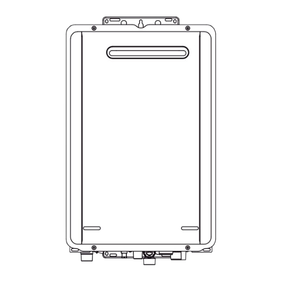
- Page 22 2.4 MAIN COMPONENTS Illustration represents E2024W. NAME NAME CASING ASS’Y GAS CONTROL ASS’Y FRINT PANEL ASS’Y WATER FLOW CONTROL DEVICE FLUE OUTLET GAS CONNECTION OVERHEAT SWITCH WATER FILTER ASS’Y HEAT EXCHANGER WATER INLET THERMAL FUSE NEUTRALIZED DRAIN OUTLET FLAME ROD NEUTRALIZER TANK DRAIN VALVE ELECTRODE PRESSURE RELIEF VALVE...
- Page 23 2.5 GENERAL SCHEME AND OPERATION PRINCIPLES *Only for REU-E2426W-E model. 2.5.1 OPERATION PRINCIPLES Ignition Press ON/OFF Button of Remote Controller to turn on unit and the remote controller display and priority LED will light up. When a hot water tap is opened the water flow Sensor revolves and sends a pulse signal to the printed circuit board (PCB). When the PCB detects water flow it compares the measured temperature to the temperature setpoint.
- Page 24 A minimum horizontal clearance of 500mm between a building structure and obstruction facing the terminal. For correct operation of Rinnai external continuous flow water heaters such a MINIMUM OBSTRUCTION HEIGHT IS TO BE NO LESS building structure MUST ‘obstruct’...
- Page 25 power. Gas pipe sizing must consider the gas input to this appliance as well as all the other gas appliances in the premises. Sufficient gas must be available at the appliance if correct operation is to be expected; insufficient gas will damage the unit. The available gas pressure affects directly the power output and can result in discomfort if not correct.
- Page 26 III. The appliance is equipped with power cord and plug: if the cable has to be replaced contact qualified professionals and use original Rinnai parts only not to invalidate the warranty. Do not use adaptors, multiple socket or extension cords.
- Page 27 • The FOURTH water controller in any installation must be an universal water controller. For more information regarding deluxe kitchen and bathroom water controllers, contact Rinnai or visit: www.rinnai.it. Location • Do not install water controllers near a heat source, such as a cook top, stove or oven. Heat, steam, smoke and hot oil may cause damage.
- Page 28 2.7.2 UNIVERSAL WATER CONTROLLER (MC-601) INSTALLATION 1. Determine the most suitable position. 2. Mark and drill 3 holes (mounting and cable access) for water controller dimensions. Film Controller Cable Cover Plates Screws Connector Fig. 1 Fig. 2 Fig. 3 Fig. 4 3.
- Page 29 • After testing is completed, explain to the householder the functions and operation of the water heater and water controllers (if fitted). Remind the customer to complete the warranty card and forward to Rinnai. • Inform customer on use of an adequate water softening system to prevent damages to heat exchanger.
- Page 31 3. M AINTENANCE INSTRUCTIONS The following section provides specific instructions for proper maintenance of the product. This section is intended for the use by qualified technical personnel.
- Page 32 3.1 PCB INTERFACE LAYOUT AND FUNCTIONS Operation of the PCB interface To enter into the PCB’s programming mode press PB2 until the Communication interface socket LED digital display shows “1” (Gas type); the current set value of PB1 - Data transfer button: “menu 1”...
- Page 33 3.2 GAS CONVERSION AND PRESSURE ADJUSTMENT Only qualified professionals are authorized to carry out the operations described. The product warranty does not cover any alterations due to non-qualified personnel. IMPO TANT The min and max gas operating pressures are factory pre-set: under normal circumstances any adjustment is not required during installation.
- Page 34 3.3 DATA TRANSFER BETWEEN PCB’S If a new PCB needs replacing, you can transfer data (gas type, model type, gas pressure and error history) from the existing PCB to the new one by doing the following: 1. Check the current settings and note them on a piece of paper. 2.
- Page 35 3.5 FLOW CHART...
- Page 36 3.6 WIRING DIAGRAM AND DIAGNOSTIC POINTS MEASUREMENT POINT COMPONENT RANGE OF VALUE CN/Con.re WIRE COLOUR MAIN POWER CODE BR-BL AC198-264V REMOTE CONTROLLER DC11-14V ANTI-FREEZE HEATER 446-514Ω VALVE HEATER 139-161Ω NEUTRALIZER TANK HEATER 6472-7517Ω IGNITER R-BK DC11-14V (DURING IGNITION) FLAME ROD Y-BODY (GND) OVER AC2V (DURING OPERATION) THERMAL FUSE...
- Page 37 The appliance must be inspected, repaired and maintained by a licensed professional. The licensed professional must verify proper operation after servicing. For more detailed instructions on maintenance contact Rinnai or your supplier. Cleaning It is imperative that control compartments, burners, and circulating air passageways of the appliance be kept clean. Clean as follows: 1.
- Page 38 3.7.1 FLUSHING THE HEAT EXCHANGER The procedure for flushing the exchanger is shown below. Flushing the heat exchanger removes the limescale deposits that form with the use of the appliance. The formation of limescale deposits depends on various factors: the quality of the water used, the temperature of use, and the frequency of use.
- Page 39 3.7.2 MANUAL DRAINING OF THE WATER HEATER If the water heater is not going to be used during a period of possible freezing weather, it is recommended that the water inside the water heater be drained. To manually drain the water: 1.
- Page 40 3.8 TECHNICAL DATA Infinity Model REU-E1620W-E REU-E2024W-E REU-E2426W-E Unit Installation External, outdoor G20 Nat Gas min gas pression mbar G20 Nat Gas max gas pression 8. 1 mbar G230 Air/Propane min gas pression 2. 1 mbar G230 Air/Propane max gas pression 10.0...
- Page 41 3.9 PRODUCT FICHE Unit Supplier’s name Rinnai Italia srl Supplier’s model REU-E1620W-E Load profile Water heating energy efficiency class Water heating energy efficiency (ŋ 90.2 Annual electricity consumption (AEC) kWh/annum Annual fuel consumption (AFC) - (Hs) GJ/annum Temperature setting °C Indoor sound power level (LWA) Values tested with appliance set @60°C - Gas: G20mbar - High calorific value (Hs) - According to Reg.
- Page 42 NOTE...
- Page 44 Via Liguria, 37 41012 - Carpi, Modena U339-1171(00) Tel: +39 059 622 9248 e-mail: info@rinnai.it rinnai.it 39759 8 060 00012 V. 1- 230524 - This manual edition replaces any previously published ones.
Need help?
Do you have a question about the REU-E2024W-E and is the answer not in the manual?
Questions and answers