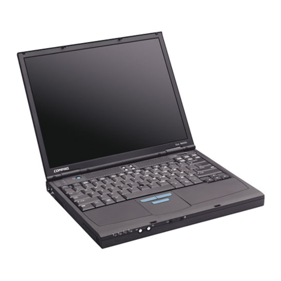
Compaq Evo N600c Series Hardware Manual
Hp evo n600c: hardware guide
Hide thumbs
Also See for Evo N600c Series:
- Maintenance and service manual (217 pages) ,
- Quickspecs (26 pages) ,
- User manual (172 pages)
Table of Contents
Advertisement
b
Hardware Guide
Evo Notebook N600c Series
Document Part Number: 229045-002
November 2001
This guide identifies computer hardware features and provides
procedures for using them. It also includes instructions for setting
up the computer, information about connecting external devices,
and computer specifications.
Advertisement
Table of Contents

Related Manuals for Compaq Evo N600c Series


Summary of Contents for Compaq Evo N600c Series
- Page 1 Hardware Guide Evo Notebook N600c Series Document Part Number: 229045-002 November 2001 This guide identifies computer hardware features and provides procedures for using them. It also includes instructions for setting up the computer, information about connecting external devices, and computer specifications.
- Page 2 © 2001 Compaq Computer Corporation Compaq and the Compaq logo Registered in U. S. Patent and Trademark Office. Evo is a trademark of Compaq Information Technologies Group, L.P. Microsoft, MS-DOS, Windows, Windows NT are trademarks of Microsoft Corporation. All other product names mentioned herein may be trademarks of their respective companies.
-
Page 3: Table Of Contents
Contents 1 Hardware and Software Setup Setting Up the Hardware ......1–1 Setting Up the Software ......1–4 Installing Optional Applications. - Page 4 Contents Using the Dual Pointing Device (Dual Models)..3–3 Setting Pointing Device Preferences ... . 3–4 Replacing the Pointing Stick Cap ....3–5 Using Hotkeys and Shortcut Keys .
- Page 5 Contents 5 Removable Drives Adding a Drive to the System ..... 5–1 Caring for Drives....... 5–2 Removing and Inserting a Primary Hard Drive .
- Page 6 Contents Connecting an External Diskette Drive Bay ..7–4 Connecting a USB Device......7–4 Using a USB Device.
-
Page 7: Hardware And Software Setup
Hardware and Software Setup Setting Up the Hardware Ä CAUTION: Setup must begin with connecting the computer to AC power. To prevent file corruption, possible damage to components, and ensure that the correct drivers load during initial setup: Do not set up the computer while it is docked in an optional docking base. - Page 8 Hardware and Software Setup 1. Place the computer on a flat surface near an electrical outlet, then connect the computer to external AC power. Plug the AC Adapter cable into the DC power connector 1 . Plug the power cord into the AC Adapter 2 and into an electrical outlet 3 .
- Page 9 Hardware and Software Setup 3. Turn on the computer by sliding and releasing the power switch 1 . Turning on the computer When the computer is turned on: The power/suspend light 2 turns on. The battery pack in the battery bay begins to charge and the battery light 3 turns on.
-
Page 10: Setting Up The Software
Hardware and Software Setup Setting Up the Software The initial setup prompt appears on the screen as soon as the computer is connected to external power. Before responding to the initial setup prompt and proceeding through the online instructions, read the following caution and initial setup information: Ä... -
Page 11: After Software Setup
Hardware and Software Setup To install a preloaded Compaq utility, select the Setup Compaq Software icon on the Desktop, then follow the instructions on the screen. If the icon does not display on the Desktop after initial setup is complete, select Start > Run. On the command line, type: C:\cpqapps\setup.exe preload /s ✎... - Page 12 Hardware and Software Setup Hibernation can be initiated by default as described below, but it may be more convenient to initiate it from a button or switch. ❏ Microsoft Windows 98 or Microsoft Windows 2000 Professional operating system—By default Hibernation can be initiated only from the Windows Shut Down menu.
-
Page 13: Look At The Computer
A Look at the Computer Display Components Identifying display components Display components and their functions Display release latch Opens the computer. MultiPort Supports an optional USB-enabled wireless device such as a Bluetooth, 802.11 wireless LAN, or PC Smart Card Reader module. Hardware Guide 2–1... -
Page 14: Pointing Device Components (Pointing Stick Models)
A Look at the Computer Pointing Device Components (Pointing Stick Models) Identifying pointing stick components Pointing stick components and their functions EasyPoint IV™ 3D Pointing Moves the pointer, selects, and Stick activates. Left and right pointing-stick Function like the left and right buttons buttons on an external mouse. -
Page 15: Pointing Device Components (Touchpad Models)
A Look at the Computer Pointing Device Components (TouchPad Models) Identifying TouchPad components TouchPad components and their functions TouchPad Moves the pointer, selects, and activates. Left and right TouchPad Function like the left and right buttons buttons on an external mouse. Hardware Guide 2–3... -
Page 16: Pointing Device Components (Dual Models)
A Look at the Computer Pointing Device Components (Dual Models) Identifying dual pointing device components Dual pointing device components and their functions Pointing stick Moves the pointer, selects, and activates. Left and right pointing-stick Function like the left and right buttons buttons on an external mouse. -
Page 17: Top Components: Speakers, Mini Pci Compartment
A Look at the Computer Top Components: Speakers, Mini PCI Compartment Identifying the speakers and mini PCI compartment Speakers and mini PCI compartment and their functions Stereo speakers (2) Produce stereo sound. Mini PCI (personal Supports an optional modem card, computer interface) combination modem/NIC (network compartment... -
Page 18: Top Components: Lights
A Look at the Computer Top Components: Lights Identifying the lights on the top of the computer 2–6 Hardware Guide... - Page 19 A Look at the Computer Lights on the top of the computer and their functions Caps lock light On: Caps lock is on. Scroll lock light On: Scroll lock is on. Num lock light On: Num lock is on or the embedded numeric keypad is enabled.
-
Page 20: Top Components: Buttons, Keys, Switches
A Look at the Computer Top Components: Buttons, Keys, Switches Identifying the buttons, keys and switches on the top of the computer 2–8 Hardware Guide... -
Page 21: And Their Functions
A Look at the Computer Buttons, keys and switches on the top of the computer and their functions † Suspend button Turns on the computer if it is off. †‡ Initiates and exits Suspend. When pressed while sliding the power switch, resets the computer. -
Page 22: Left Side Components
A Look at the Computer Left Side Components Identifying left side components Left side components and their functions Network speed light On: Connection speed is 100 Mb/Sec. (network models only) Off: Connection speed is 10 Mb/Sec. RJ-45 jack Connects the network cable. A network cable is included with network models. -
Page 23: Right Side Components
A Look at the Computer Right Side Components Identifying right side components Right side components and their functions Security cable slot Attaches an optional security cable to the computer. MultiBay Supports optional MultiBay devices. RJ-11 jack (internal modem Connects the modem cable. A models only) modem cable is included with internal modem models. -
Page 24: Front Panel Components
A Look at the Computer Front Panel Components Identifying front panel components Front panel components and their functions Infrared port Links another IrDA-compliant device for wireless communication. Volume buttons (2) Adjust or mute system volume. Stereo speaker/headphone Connects optional, powered stereo (line-out) jack speakers, headphones, headset, or television audio. -
Page 25: Rear Panel Components
A Look at the Computer Rear Panel Components Identifying rear panel components Rear panel components and their functions DC power connector Connects an AC Adapter or an optional Automobile Power Adapter/Charger, Aircraft Power Adapter, or DC cable. Keyboard/pointing device Connects an optional PS/2 device (PS/2) connector such as a keyboard or mouse. -
Page 26: Bottom Components
A Look at the Computer Bottom Components Identifying bottom components ✎ The location of the Certificate of Authenticity label ( 8 ) may vary by model and configuration. 2–14 Hardware Guide... - Page 27 A Look at the Computer Bottom components and their functions MultiBay recess Provides a grip area for removing an optional MultiBay device from the MultiBay. MultiBay release latch Releases an optional MultiBay device from the MultiBay. System label Provides regulatory information about the computer.
-
Page 28: Additional Standard Components
A Look at the Computer Additional Standard Components The components included with the computer vary by geographical region and the computer hardware configuration ordered. The following illustration and table identify the standard external components included with most computer models. ✎ This illustration does not include printed documentation or such components as the hard drive and primary battery pack, which ship inside computer bays identified in previous sections. - Page 29 A Look at the Computer Additional standard components and their functions Power cord Connects the AC Adapter to an AC electrical outlet. Modem cable (internal Connects the modem to an RJ-11 modem models only) telephone jack or to a country-specific modem adapter.
- Page 30 A Look at the Computer Additional standard components and their functions (continued) Notebook Products Contains the following guides: Reference Library CD Hardware Guide Compaq Utilities Modem and Networking Modem Commands Maintenance, Shipping and Travel Troubleshooting Regulatory and Safety Notices Safety & Comfort Guide Bag containing 2 spare Replace worn pointing stick cap.
-
Page 31: Pointing Devices And Keyboard
Pointing Devices and Keyboard Using a Pointing Device Using the Pointing Stick (Pointing Stick Models) To move the cursor, press the pointing stick 1 in the direction you want to move the cursor. Use the left 2 and right 3 pointing-stick buttons as you would the left and right buttons on an external mouse. -
Page 32: Using The Touchpad (Touchpad Models)
Pointing Devices and Keyboard Using the TouchPad (TouchPad Models) To move the cursor, slide your finger across the TouchPad surface 1 in the direction you want to move the cursor. Use the left 2 and right 3 TouchPad buttons as you would the left and right buttons on an external mouse. -
Page 33: Using The Dual Pointing Device (Dual Models)
Pointing Devices and Keyboard Using the Dual Pointing Device (Dual Models) By default, the pointing stick and TouchPad components can be used interchangeably. Using the Pointing Stick Components To move the cursor, press the pointing stick 1 in the direction you want to move the cursor. -
Page 34: Setting Pointing Device Preferences
Pointing Devices and Keyboard Setting Pointing Device Preferences Pointing Stick, TouchPad, and Dual Device Preferences All pointing devices are supported by the mouse software in your operating system. To access the custom settings available in the software, select Start > Settings > Control Panel > Mouse. All pointing devices perform mouse functions with any software that supports a Windows-compatible mouse. -
Page 35: Replacing The Pointing Stick Cap
Pointing Devices and Keyboard ❏ To change the language, press ❏ For navigation instructions, press 3. Select Advanced > Device Options, then press enter. 4. In the Internal Pointing Devices field, select among: ❏ Both—To enable all dual device components. ❏... -
Page 36: Using Hotkeys And Shortcut Keys
Pointing Devices and Keyboard Using Hotkeys and Shortcut Keys Hotkeys and shortcut keys are preset combinations of the key 1 and another key that access or execute frequently used system functions. A hotkey is a combination of the key and one of the function keys 2 . -
Page 37: Hotkey And Shortcut Key Quick Reference
Pointing Devices and Keyboard Hotkey and Shortcut Key Quick Reference Function Hotkey Return to Original State Turn a device in the Fn+F2 Fn+F2 MultiPort on or off.* Switch display and Fn+F4 Fn+F4 image. Adjust system volume. Fn+F5 Fn+F5 Initiate Quick Controls. Fn+F6 Enter power-on password Set power conservation... -
Page 38: Hotkey And Shortcut Key Procedures
Pointing Devices and Keyboard Hotkey and Shortcut Key Procedures Most hotkeys and shortcut keys can be used as described at anytime and from within any application, with 2 exceptions: To use hotkeys or shortcut keys on an external keyboard, press the key twice, then the other key only of the scroll lock hotkey combination. -
Page 39: Switch Display And Image (Fn+F4)
Pointing Devices and Keyboard 4. Select MultiPort Fn+F2. The status of the device in the MultiPort is displayed at the bottom of the screen. 5. To change the status of the device in the MultiPort, press the hotkeys. The device in the MultiPort will remain in Fn+F2 the status you select when the hotkeys are disabled. -
Page 40: Adjust System Volume (Fn+F5)
Pointing Devices and Keyboard Adjust System Volume (Fn+F5) Press to display a system volume slide bar. Click and drag Fn+F5 the slide bar upward to increase volume or downward to decrease volume. You also can adjust the volume by pressing then pressing Fn+F5, the left and right arrow keys. -
Page 41: Set Power Conservation Level (Fn+F7)
Pointing Devices and Keyboard Set Power Conservation Level (Fn+F7) Windows 98 or Windows 2000 Professional—Press Fn+F7 to open the Power Schemes window. Windows NT 4.0—Press to open the Battery Fn+F7 Conservation Settings window. To select a preset battery conservation level, choose among: ❏... -
Page 42: Adjust Screen Brightness (Fn+F10)
Pointing Devices and Keyboard Adjust Screen Brightness (Fn+F10) Press to display the screen brightness control slide Fn+F10 bar, then: Click and drag upward on the slide bar to increase screen brightness or downward to decrease screen brightness. Press the left arrow key to decrease screen brightness or the right arrow key to increase screen brightness. -
Page 43: Using The Fn Key Sequentially
Pointing Devices and Keyboard Using the Fn Key Sequentially Many commands are entered by simultaneously pressing the key and another key. For example, hotkey commands are entered by pressing a function key. Fn + If you enable sequential commands, all commands that can be entered by simultaneously pressing the key and another key can also be entered by sequentially pressing... -
Page 44: Using The Embedded Numeric Keypad
Pointing Devices and Keyboard Using the Embedded Numeric Keypad The 15 keys of the embedded numeric keypad 1 can be used for the functions indicated by the icons in the upper right corner of each key. Enabling the numeric keypad assigns those functions to the keypad keys. -
Page 45: Using Numeric Keypad Keys As Standard Keys
Pointing Devices and Keyboard Using Numeric Keypad Keys as Standard Keys To use the numeric keypad keys temporarily as standard keys while the numeric keypad is enabled: Press and hold to type in lowercase. Press and hold to type in uppercase. Fn+shift When the key is released, the numeric keypad functions return. -
Page 46: Using The Easy Access Buttons
Pointing Devices and Keyboard Using the Easy Access Buttons The 4 Easy Access buttons enable you to access an Internet or network destination or a software application or data file in your system with a keystroke. Using Default Settings Until your Internet or network services are set up, all buttons launch the Internet setup wizard for your operating system. -
Page 47: Using Custom Assignments And Schemes
Pointing Devices and Keyboard Using Custom Assignments and Schemes Each button can be assigned to an Internet or network destination or to any software application or data file in your system. Button assignments can be grouped into schemes. When you select a scheme, only the button assignments within that scheme are active. -
Page 48: Battery Packs
Battery Packs Charging Battery Packs Any battery pack in the system charges whenever the computer is connected to external power. The computer supports up to 2 battery packs. A primary battery pack 1 is an 8-cell lithium ion battery pack that can be used only in the battery bay. A MultiBay battery pack 2 is an optional 6-cell lithium ion battery pack that can be used only in the MultiBay. -
Page 49: Using A New Battery Pack
Battery Packs Charge sequence: 1. Computer battery bay 2. Computer MultiBay 3. Docking base bay(s) (Docking base bay availability and functionality vary by model and configuration. For information about charging battery packs in your docking base, refer your docking base documentation.) Discharge sequence: 1. -
Page 50: Replacing A Primary Battery Pack
Battery Packs Replacing a Primary Battery Pack Ä CAUTION: To prevent loss of information when removing a primary battery pack that is the only power source available to the system, initiate Hibernation or turn off the computer before removing the battery pack. -
Page 51: Replacing A Multibay Battery Pack
Battery Packs Replacing a MultiBay Battery Pack Ä CAUTION: To prevent loss of information when removing a MultiBay battery pack that is the only power source available to the system, initiate Hibernation or turn off the computer before removing the battery pack. 1. -
Page 52: Storing A Battery Pack
Battery Packs Storing a Battery Pack If a computer will be unused and unplugged for more than 2 weeks, remove and store the battery pack(s). Ä CAUTION: To prevent damage to a battery pack, do not expose it to high temperatures for extended periods of time. High temperatures accelerate the self-discharge rate of a stored battery pack. -
Page 53: Removable Drives
Removable Drives Adding a Drive to the System Removable drives enable you to store and access data. A standard drive can be added to the system by inserting the drive into the computer or an optional docking base. A diskette drive can also be inserted into an optional external diskette drive bay. -
Page 54: Caring For Drives
Removable Drives Caring for Drives Drives are fragile computer components that must be handled with care. Ä CAUTION: To prevent damage to the computer and drive and loss of information, ensure that you are discharged of static electricity before handling a drive. Avoid touching the connectors on the drive. For more information about preventing electrostatic discharge damage, refer on this CD to Regulatory and Safety Notices. - Page 55 Removable Drives 4. Remove the hard drive retaining screw. Removing the hard drive retaining screw 5. With the drive bottom-side up, slide the bottom half of the front bezel upward to provide a handle. Extending the front bezel to provide a handle Hardware Guide 5–3...
- Page 56 Removable Drives 6. To remove a hard drive, pull the drive out of the bay. Removing the hard drive from the hard drive bay 7. To insert a hard drive, slide the hard drive into the bay until the drive is seated. Inserting the hard drive into the hard drive bay 5–4 Hardware Guide...
- Page 57 Removable Drives 8. Close the front bezel of the hard drive. Closing the front bezel of a hard drive 9. If you have inserted a hard drive, reinsert the hard drive retaining screw. (If you removed but did not replace a hard drive, put the retaining screw in a safe place.) Replacing the hard drive retaining screw Hardware Guide...
-
Page 58: Removing And Inserting A Multibay Drive
Removable Drives Removing and Inserting a MultiBay Drive Using a MultiBay Hard Drive Adapter A hard drive must be inserted into a MultiBay hard drive adapter before it can be used in the MultiBay. A hard drive assembly (a hard drive inserted into a MultiBay adapter) is inserted into and removed from the MultiBay the same way as any other MultiBay drive. - Page 59 Removable Drives 2. Slide the 2 adapter selection switches into position 1. Sliding the adapter selection switches 3. Lower the drive into the adapter 1 , then slide the drive connectors on the drive toward the drive connectors in the adapter 2 until the connectors engage and the drive is seated.
- Page 60 Removable Drives Removing a Hard Drive from a MultiBay Hard Drive Adapter 1. Slide the adapter release latch toward the left. Sliding the adapter release latch 5–8 Hardware Guide...
-
Page 61: Removing A Drive From The Multibay
Removable Drives 2. Gently disengage the drive connectors 1 by sliding the drive toward the front of the adapter. 3. Remove the drive from the adapter 2 . Removing a hard drive from a MultiBay hard drive adapter Removing a Drive from the MultiBay CAUTION: To prevent system lockup and loss of information: Windows 98 or Windows NT 4.0—Shut down the computer before removing a hard drive or a Zip drive from the MultiBay. - Page 62 Removable Drives 1. If the drive has a media tray, remove the media, then close the tray. 2. Follow the instructions in the preceding caution, then close the display. 3. Turn the computer bottom-side up 1 . 4. Slide the MultiBay release latch 2 toward the rear of the computer.
-
Page 63: Inserting A Drive Into The Multibay
Removable Drives Inserting a Drive into the MultiBay 1. Before inserting a hard drive into the MultiBay: ❏ Insert the drive into a MultiBay hard drive adapter as described earlier in this section. ❏ Ensure that the hard drive bezel is closed before inserting the hard drive assembly (a hard drive inserted into a MultiBay hard drive adapter) into the MultiBay. -
Page 64: Inserting And Removing Drive Media
Removable Drives Inserting and Removing Drive Media Inserting a CD, CD-RW or DVD 1. Turn on the computer. 2. Press the media release button 1 on the drive bezel to release the media tray, then pull the tray outward until it is fully extended 2 . -
Page 65: Removing A Cd, Cd-Rw Or Dvd (Power)
Removable Drives Removing a CD, CD-RW or DVD (Power) If power is available: 1. Turn on the computer. 2. Press the release button 1 on the drive bezel to release the media tray, then pull the tray outward until it is fully extended 2 . -
Page 66: Removing A Cd, Cd-Rw Or Dvd (No Power)
Removable Drives Removing a CD, CD-RW or DVD (No Power) If power is unavailable: 1. Insert a paper clip into the release access 1 in the front bezel of the drive. 2. Press gently on the paper clip until the media tray is released, then pull out the tray until it is fully extended 3. -
Page 67: Inserting A Diskette Or Disk
Removable Drives Inserting a Diskette or Disk To insert a diskette or disk into a diskette, SuperDisk, or Zip drive: Gently push the medium, label side up, into the drive until it clicks into place. The media eject button ejects to show the medium is inserted correctly. -
Page 68: Initiating Suspend Or Hibernation
Removable Drives Initiating Suspend or Hibernation Ä CAUTION: To prevent possible video degradation and loss of audio or video playback functionality, do not initiate Suspend or Hibernation while playing any media. To ensure a standard initiation of and exit from Suspend or Hibernation, turn off all media before initiating Suspend or Hibernation. -
Page 69: Audio And Video
Audio and Video Using Audio Features Identifying Audio Features The computer provides the following audio components: Identifying audio features Hardware Guide 6–1... -
Page 70: Using The Microphone Jack
Audio and Video Audio Feature Function Speakers (2) Provide stereo audio playback for multimedia applications. ✎ When the computer is docked in an optional docking base, the computer speakers are disabled and system sound plays through the docking base speakers. For more information, refer to the documentation included with the expansion base. -
Page 71: Using The Stereo Speaker/Headphone Jack
Audio and Video Using the Stereo Speaker/Headphone Jack Å WARNING: To reduce the risk of personal injury, adjust the volume before putting on headphones or a headset. Ä CAUTION: To prevent possible damage to an external device, do not plug a single-sound channel (monaural) connector into the stereo speaker/headphone (line-out) jack. -
Page 72: Using Video Features
Audio and Video Windows Volume Control window ❏ To open the window and access the volume settings, double-click the volume icon on the taskbar. ❏ To activate the Widows Volume Control window while it is open but inactive, press the hotkeys. -
Page 73: Changing The Video Mode
Audio and Video To connect a video device to the composite video-out jack: 1. Plug either end of the composite video cable into the composite video-out jack on the computer 1 . 2. Connect the other end of the cable to the video device as instructed in the device documentation 2 . - Page 74 Audio and Video To change the color television standard mode from NTSC: 1. Turn on or restart the computer. Press while the F10 = ROM Based Setup message is displayed in the lower left corner of the screen. ❏ To change the language, press ❏...
-
Page 75: External Device Connections
External Device Connections Connecting a Standard Device The jacks and connectors described in this guide support the standard external devices that specify them. For information about which jack or connector to use, refer to the documentation included with the device. For information about installing or loading any software such as drivers required by the device, refer to the device documentation, your operating system documentation, or the... -
Page 76: Connecting A Modem Cable
External Device Connections Connecting a Modem Cable A modem cable, which has a 6-pin RJ-11 connector at each end, must be connected to an analog telephone line. Jacks for digital PBX systems may resemble analog telephone jacks, but are not compatible with the modem. -
Page 77: Connecting A Network Cable
External Device Connections For more information about using the modem or about using AT commands and dial modifiers, refer on this CD to the Modem and Networking guide or the Modem Commands guide. Connecting a Network Cable A network cable has an 8-pin RJ-45 connector at each end and may contain noise suppression circuitry, which prevents interference with TV and radio reception. -
Page 78: Connecting An External Diskette Drive Bay
External Device Connections Connecting an External Diskette Drive Bay An optional external diskette drive bay supports only a diskette drive. No other type of drive, including a SuperDisk or Zip drive, can be used in this bay. To connect the external diskette drive bay, connect the free end of the diskette drive bay cable to the parallel connector on the computer 1 . - Page 79 External Device Connections USB hubs can be connected to a USB connector on the computer or a docking base or to other USB devices. Hubs support varying numbers of USB devices and are used to increase the number of USB devices in the system: Powered hubs must be connected to external power.
-
Page 80: Using A Usb Device
External Device Connections Using a USB Device USB devices function in the system the same as comparable non-USB devices, with 1 exception: By default, USB devices do not function unless an operating system that supports USB is loaded. To use a USB keyboard, mouse, or hub connected to a USB connector on the computer during startup or in a non-Windows application or utility, enable USB legacy support. -
Page 81: Linking To An Infrared Device
External Device Connections Linking to an Infrared Device If the computer is running Windows 98 or Windows 2000 Professional, the computer is IrDA-compliant (4 Mbps standard) and can communicate with another infrared-equipped device that is also IrDA-compliant. Infrared signals are sent through an invisible beam of infrared light and require an unobstructed line of sight path. -
Page 82: Configuring The Infrared Port
External Device Connections Configuring the Infrared Port If you are using optional infrared software and a preinstalled operating system, the following information may be helpful. The infrared port default settings are: ❏ DMA=1 ❏ I/O addresses=3E8-3EFh ❏ IRQ=3 The optimal port selections in Direct Cable Connection are: ❏... -
Page 83: Using Suspend With Infrared
External Device Connections Position the ports so they face each other directly. Because the maximum capture angle is 30 degrees, the ports must be aligned no more than 15 degrees off center. Shield the ports from direct sunlight, flashing incandescent light, and energy-saving fluorescent light. -
Page 84: Planning A Docking System
External Device Connections Planning a Docking System The computer is compatible with all 3 Compaq docking solutions: the Expansion Base, the Convenience Base, and the Port Replicator. Docking Considerations To ensure convenient access to the computer and its features, Compaq recommends that you consider the following before setting up your docking system. -
Page 85: Connecting An Optional Cable Lock
External Device Connections Connect your accessories to the USB port on an Expansion Base, Convenience Base, or Port Replicator instead of to a USB port on the computer. To use a wireless LAN (Local Area Network) while the computer is docked in an Expansion Base in a vertical stand, install a Compaq 802.11b MultiPort Wireless LAN module in the computer. -
Page 86: Hardware Upgrades
Hardware Upgrades To order or learn more about hardware upgrades and accessories, visit the Compaq Web site at or refer to http://www.compaq.com, Worldwide Telephone Numbers, included with the computer, to contact a Compaq authorized dealer, reseller, or service provider. For information about obtaining and installing software updates and upgrades, refer on this CD to the Maintenance, Shipping and Travel guide, “How to Get Information, Updates and Help”... -
Page 87: Configuring A Pc Card
Hardware Upgrades When the computer is used with any docking base: The computer cannot be docked while a PC Card or cable is protruding from the lower PC Card slot. The lower PC Card slot is inaccessible while the computer is docked. -
Page 88: Inserting A Pc Card
Hardware Upgrades Inserting a PC Card Ä CAUTION: To prevent damage to the connectors, use minimal pressure when inserting a PC Card into a PC Card slot. Ä CAUTION: Failure to remove a PC Card that extends beyond the computer before transporting the computer may cause permanent damage to the PC Card connectors. -
Page 89: Removing A Pc Card
Hardware Upgrades Removing a PC Card Ä CAUTION: To prevent loss of work or system lockup: Windows 98—Select the PC Card icon in the taskbar, then stop the card you plan to remove. A message displays when the card can be safely removed. Windows 2000 Professional—Select the Unplug or Eject icon in the taskbar, then stop the card you plan to remove. -
Page 90: Turning Off Power To A Pc Card
Hardware Upgrades Turning Off Power to a PC Card When a PC Card is inserted in the computer, the PC Card draws power from the system even when it is not in use. To conserve power, stop any PC Cards that are not in use: Windows 98—Select the PC Card icon in the taskbar, then select the PC Card(s) you want to stop. -
Page 91: Upgrading Memory
Hardware Upgrades Upgrading Memory You can increase RAM (random access memory) with optional PC Cards or memory expansion boards. The computer has 2 memory expansion slots and 2 PC Card slots. The PC Card slots support 2 Type I or Type II PC Cards or 1 Type III PC Card. -
Page 92: Removing Or Inserting A Memory Expansion Board
Hardware Upgrades Removing or Inserting a Memory Expansion Board Å WARNING: The memory and mini PCI compartments are the only user-accessible internal compartments on the computer. All other areas that require a tool to access should be opened only by a Compaq authorized service provider. - Page 93 Hardware Upgrades 6. Remove the 2 screws securing the memory expansion compartment cover 1 , then tilt up and remove the cover 2 . Opening the memory expansion compartment 7. Remove or insert the memory expansion board. To remove a memory expansion board: a.
- Page 94 Hardware Upgrades To insert a memory expansion board: a. Align the keyed (notched) edge of the board with the keyed area in an expansion slot 1 . (If no other memory expansion board is in the memory expansion compartment, insert the board into the lower slot.) b.
- Page 95 Hardware Upgrades 8. Align the tabs on the memory expansion compartment cover with the cover slots on the computer, then tilt the cover downward until it is seated 1 . 9. Replace the 2 screws securing the cover to the computer 2 . Closing the memory expansion compartment 8–10 Hardware Guide...
-
Page 96: Specifications
Specifications This computer has been tested and found to comply with the limits for a Class B digital device. For additional governmental agency information refer on this CD to Regulatory and Safety Notices. Regulatory Agency Series Numbers Regulatory agencies worldwide use agency series numbers for product identification. -
Page 97: Computer Dimensions
Specifications Computer Dimensions Dimension U.S. Metric Height 1.2 in. 3.1 cm Width 12.0 in. 30.76 cm Depth 9.8 in. 25.0 cm Operating Environment Factor U.S. Metric Temperature Operating 50° to 95° F 10° to 35° C Nonoperating 14° to 140° F –10°... -
Page 98: Rated Input Power
Specifications Rated Input Power Input Power Rating Operating voltage 100–120/220–240 VAC RMS Operating current 1.2/0.6 A RMS Operating frequency range 50–60 Hz AC When powered by a DC source 18.5V MAX ✎ This product is designed for IT power systems in Norway with phase-to-phase voltage not exceeding 240 Vms. - Page 99 Index audio devices, connecting external 6–2 7–1 AC Adapter Automobile Power connecting 1–2 Adapter/Charger (optional) 2–13 function of 2–17 accelerator, graphics 3–12 adapter battery bay for AC power cord. See AC device supported 2–15 Adapter location number, in battery for connecting AC Adapter to charge displays 3–11 electrical outlet (Japan only).
- Page 100 Index primary, removing 4–3 calibration of battery packs 1–5 recycling 4–5 camcorder (optional) 6–4 7–1 replacing 4–2 cap, replacing pointing stick 2–18 storing 4–5 3–5 battery release latch 2–15 caps lock light 2–7 bay. See battery bay; external card and socket services, PC Card diskette drive bay;...
- Page 101 Index Compaq utilities. See utilities, Compaq DC cable 2–13 compartment DC power connector memory expansion 2–15 8–8 connecting AC Adapter to 1–2 mini PCI 2–5 devices supported 2–13 See also battery bay; external device drivers diskette drive bay; hard drive PC Card 8–2 bay;...
- Page 102 Index display, internal removing (power unavailable) closing 1–5 2–9 5–14 expanding or centering image troubleshooting 5–16 on 3–12 DVD drive (optional) opening 1–2 IDE drive light 2–7 screen brightness 3–12 inserting DVD into 5–12 switching image to or from 3–9 inserting into MultiBay 5–11 docking base (optional) locations supported 5–1...
- Page 103 Index Fn key headphones, headset (optional) identifying 3–13 connecting 6–3 7–1 using in embedded numeric stereo speaker/headphone keyboard commands 3–14 (line-out) jack 6–1 using in hotkeys, shortcut keys Hibernation 3–6 assigning to display switch, using sequentially 3–13 power switch, or suspend function keys 3–6 button 1–5 exiting 5–16...
- Page 104 Index turn MultiPort device on or off using Suspend (Standby) with 3–8 7–9 See also shortcut keys Internet commands destinations, accessing with hub, USB 7–4 Easy Access Buttons 3–16 humidity specifications 9–2 setup wizard 3–16 IRQs (interrupt requests) 7–8 IDE (Integrated Drive Electronics) light 2–7 jack identifying components...
- Page 105 Index keyboard/pointing device (PS/2) power/suspend 1–3 2–7 connector scroll lock 2–7 connecting device to 7–1 line-out jack (stereo identifying 2–13 speaker/headphone jack) 7–1 using Y-adapter with 7–1 lock, security cable (optional) 7–11 locked system, resetting 2–9 label LS-120 drive. See SuperDisk drive Certificate of Authenticity 1–4 (optional) modem agency approvals 2–15...
- Page 106 Index monitor, external (optional) connecting to 3–16 7–3 connecting 7–1 connection light 2–10 external monitor connector connections in docking system 2–13 7–10 switching display to or from destinations, assigning Easy 3–9 Access buttons to 3–16 using with other video devices jack (RJ-45 jack) 7–3 6–4 Modem and Networking guide...
- Page 107 Index overhead projector (optional) enabling optional composite video-out jack 6–4 non-Windows 3–4 connecting 7–1 pointing stick models 3–1 3–4 external monitor connector replacing pointing stick cap 2–13 2–18 switching display to or from setting preferences 3–4 3–9 TouchPad models 3–2 3–4 using with other video devices port...
- Page 108 Index Maintenance, Shipping and Travel guide 2–18 RAM (Random Access Memory) shortcut keys 8–6 entering commands from regulatory information optional external keyboard agency series numbers 9–1 3–8 Class B designation (FCC) entering commands 2–18 sequentially 3–13 modem agency approvals label Quick Reference to commands 2–15 3–7...
- Page 109 Index speakers, external (optional) power 1–3 1–5 2–9 connecting 6–3 7–1 See also button(s); key; latch stereo speaker/headphone system label 2–15 (line-out) jack 6–1 speakers, internal stereo 6–1 telephone jack (RJ-11jack) 7–2 stand, vertical, using Expansion telephone line Base in 7–10 analog vs.
- Page 110 Index video devices (optional), connecting external 6–4 7–1 video-out jack, composite 6–4 7–1 connections in docking system volume, adjusting 2–12 6–3 7–10 devices, connecting 7–4 keyboard, using hotkeys with weight saver 2–17 5–10 3–8 weight, computer 9–2 legacy support 7–6 Windows application key 2–9 wireless devices 2–1 wireless LAN (Local Area...
Need help?
Do you have a question about the Evo N600c Series and is the answer not in the manual?
Questions and answers