
Related Manuals for JYTEK PXIe-3117a


Summary of Contents for JYTEK PXIe-3117a
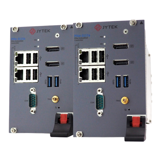
- Page 1 PXIe-3117a/3115a PXI Express Embedded Controller User’s Manual Manual Rev.: Revision Date: Aug. 28, 2024...
-
Page 2: Revision History
Revision History Revision Release Date Description of Change(s) 2024-8-28 Initial release... -
Page 3: Preface
Restriction of Hazardous Substances (RoHS) directive and Waste Electrical and Electronic Equipment (WEEE) directive. Environmental protection is a top priority for JYTEK. We have enforced measures to ensure that our products, manufacturing processes, components, and raw materials have as little impact on the environment as possible. -
Page 4: California Proposition 65 Warning
California Proposition 65 Warning WARNING: This product can expose you to chemicals including acrylamide, arsenic, benzene, cadmium, Tris(1,3-dichloro-2-propyl)phosphate (TDCPP), 1,4-Dioxane, ane, formaldehyde, lead, DEHP, styrene, DINP, BBP, PVC, and vinyl materials, which are known to the State of California to cause cancer, and acrylamide, benzene, cadmium, lead, mercury, phthalates, toluene, DEHP, DIDP, DnHP, DBP, BBP, PVC, and vinyl materials, which are known to the State of California to cause birth defects or... -
Page 5: Table Of Contents
2 Getting Started ..............17 Package Contents ............. 17 Operating System Installation ..........17 2.2.1 Installation Environment ........... 18 2.2.2 Installing the PXIe-3117a/3115a....... 20 2.2.3 Replacing the Hard Drive or Solid State Drive ..23 2.2.4 Replacing the Battery Backup ........25 2.2.5... - Page 6 3 Driver Installation.............. 27 A Appendix: PXI Trigger I/O Function Reference....29 Data Types................. 29 Function Library ..............30 A.2.1 JYSM_Trig_Open.............30 A.2.2 JYSM_Trig_Close............ 31 A.2.3 JYSM_Trig_SetConfig..........31 A.2.4 JYSM_Trig_GetConfig ..........32 A.2.5 JYSM_Trig_SetValue ..........33 A.2.6 JYSM_Trig_GetValue..........33 A.2.7 JYSM_Trig_SetRouteSignal ........34 A.2.8 JYSM_Trig_GetRouteSignal........
- Page 7 This page intentionally left blank. viii...
-
Page 8: List Of Figures
PXIe-3117a/3115a List of Figures Figure 1-1: Functional Block Diagram..........3 Figure 1-2: Front Panel ..............7 Figure 1-3: PXI Trigger SMB Jack ............. 8 Figure 1-4: DisplayPort Connector............. 9 Figure 1-5: LED Indicators ............... 11 Figure 1-6: COM Port............... 14... - Page 9 This page intentionally left blank.
-
Page 10: List Of Tables
PXIe-3117a/3115a List of Tables Table 1-1: Front Panel Legend ............7 Table 1-2: DisplayPort Pin Assignment ..........9 Table 1-3: LED Indicator Legend ............ 11 Table 1-4: USB 2.0 Port Pin Assignment........12 Table 1-5: Ethernet Port Pin Assignments........12 Table 1-6: D-sub COM Port Signal Functions......... - Page 11 This page intentionally left blank.
-
Page 12: Introduction
PXIe-3117a/3115a Introduction The JYTEK PXIe-3117a/3115a PXI Express embedded controllers are designed to offer a cost-effective solution for hybrid PXI Express-based testing systems while maintaining strong performance. Based on the 9th and 8th generation Intel Core™ i7/i5 processors, these controllers ®... -
Page 13: Features
1.1 Features -5 PXI Express Hardware Specification Rev.1.1 PXIe-3117a: Intel Core™ i7-9850HE ® (Base Frequency 2.7 GHz, Turbo Frequency 4.4 GHz) PXIe-3115a: Intel Core™i5-8400H ® (Base Frequency 2.5 GHz, Turbo Frequency 4.2 GHz) DDR4-2400MHz SODIMM x2 Default: 16GB, up to 64GB 2400 MHz ... -
Page 14: Specifications
Supports 2400 MHz RAM up to 64 GB total Supports non-ECC, unbuffered memory The externally accessible SODIMM socket can accept replacement DDR4 DRAM DIMM modules. PXIe-3117a/3115a specifications and stability guarantees are only NOTE: NOTE: supported when JYTEK-provided DDR4 DRAM SODIMM modules are used. Introduction... - Page 15 Video DisplayPort supports up to 3840 x 2160 @ 60Hz resolution 3840 x 2160 @60Hz DisplayPort adapters to other standards are available,w/max.resolutiondependent on adapter. Support only DisplayPort to HDMI and VGA. DisplayPort adapters for other standards are available, with maximum available resolution dependent on the adapter chosen NOTE:...
-
Page 16: Shock And Vibration
Functional shock 30G, half-sine, 11ms pulse duration Random vibration: Operating 5 to 500Hz, 0.21Grms, 3 axes Non-operating 5 to 500Hz, 2.46Grms, 3 axes Environmental & Shock and Vibration values are only guaranteed with use of an JYTEK provided SSD. NOTE: NOTE: Introduction... -
Page 17: Power Requirements
Power Requirements Typical Consumption DC +3.3V DC +5V DC +12V Typical operation 4.50 A 0.10 A 1.94 A (Measured while W10 is idle) Heavy operation (Measured while W10 is under heavy 6.79 A 4.00 A 7.32 A CPU and storage utilization) Introduction... -
Page 18: I/O And Indicators
PXIe-3117a/3115a 1.3 I/O and Indicators 1.3.1 Front Panel Figure 1-2: Front Panel 2x DisplayPort 2x Gigabit Ethernet 4x Type-A USB 2.0 LED indicators 2 USB 3.2 Reset PXI Trigger COM port Table 1-1: Front Panel Legend Introduction... -
Page 19: Figure 1-3: Pxi Trigger Smb Jack
The PXI trigger connector is an SMB jack, used to route external trigger signals to or from the PXI backplane. Trigger signals are TTL-compatible and edge sensitive. The PXIe-3117a/3115a provides four trigger routing modes from/to the PXI trigger connector to synchronize PXI modules, including From a selected trigger bus line to PXI trigger connector ... -
Page 20: Figure 1-4: Displayport Connector
PXIe-3117a/3115a Figure 1-4: DisplayPort Connector Signal Signal CN_DDPx0+ CN_DDPx3- CN_DDPx0- CN_DDPx_AUX_SEL CN_DDPx1+ CN_DDPx_CONFIG2 CN_DDPx_AUX+ CN_DDPx1- CN_DDPx2+ CN_DDPx_AUX- CN_DDPx_HPD CN_DDPx2- CN_DDPx3+ +V3.3_DDPx_PWR Table 1-2: DisplayPort Pin Assignment Introduction... -
Page 21: Reset Button
1.3.2 Reset Button The reset button, activated by insertion of any pin-like implement, executes a hard reset for the PXIe-3117a/3115a. Introduction... -
Page 22: Led Indicators
Table 1-3: LED Indicator Legend 1.3.4 USB 2.0 Ports The PXIe-3117a/3115a provides four USB 2.0 ports via USB Type-A connectors on the faceplate, all compatible with hi- speed, full-speed and low-speed USB devices. Supported boot devices include USB flash drive, USB floppy, USB CD-ROM, and... -
Page 23: Gigabit Ethernet Ports
Power 5V USB Data- USB Data + Ground Table 1-4: USB 2.0 Port Pin Assignment 1.3.5 Gigabit Ethernet Ports Dual Gigabit Ethernet connection is provided on the PXIe-3117a/3115a front panel. 1000Base-T Signal 100/10Base-T Signal MDI0+ MDI0- MDI1+ MDI2+ Reserved MDI2-... -
Page 24: Usb 3.0 Ports
1000 Mbps 1.3.6 USB 3.2 Ports The PXIe-3117a/3115a provides two Type-A USB 3.2 ports on the front panel, supporting SuperSpeed, Hi-Speed, full-speed, and low- speed transmission for downstream. Multiple boot devices, including USB flash, USB external HD, and USB CD-ROM drives are supported, with boot priority configured in BIOS. -
Page 25: Com Port
1.3.7 COM Port A COM port on the front panel with a D-sub 9-pin connector supports RS-232 Figure 1-6: COM Port Signal Name RS-232 Table 1-6: D-sub COM Port Signal Functions Introduction... -
Page 26: Onboard Connections And Settings
PXIe-3117a/3115a 1.3.8 Onboard Connections and Settings Figure 1-7: Onboard Configuration Clear CMOS switch M.2 connector System battery Table 1-7: Onboard Configuration Legend Introduction... - Page 27 This page intentionally left blank. Introduction...
-
Page 28: Getting Started
PXIe-3117a/3115a Getting Started This chapter describes procedures for installing the PXIe-3117a/3115a and making preparations for its operation, includ-ing hardware and software setup. Please note that the PXIe-3117a/3115a is shipped with RAM and SSD preinstalled. Please contact JYTEK or authorized dealer if there are any problems during the installation. -
Page 29: Installation Environment
Most operating systems require initial installation from a hard drive, floppy drive, or CD-ROM drive. The PXIe-3117a/3115a controller supports USB CD-ROM drive, USB flash disk, USB external hard drive, or a USB floppy drive as the first boot device. These... - Page 30 Anti-static wrist strap Anti-static mat JYTEK PXIe-3117a/3115a system controllers are electrostatically sensitive and can be easily damaged by static electricity. The equipment must be handled on a grounded anti- static mat, and operators must wear an anti-static wristband, grounded at the same point as the anti-static mat.
-
Page 31: Installing The Pxie-3117A/3115A
2.2.2 Installing the PXIe-3117a/3115a 1. Remove all screw caps (x4). Getting Started... - Page 32 PXIe-3117a/3115a 2. Release the red locking lever. 3. Depress the latch. 4. Locate the system controller slot on the chassis (Slot 1). Getting Started...
- Page 33 PXIe-3117a/3115a into the chassis, as shown 6. Elevate the latch until the PXIe-3117a/3115a is fully seated in the chassis backplane. The alignment pin on the rear of the latch can be threaded into the best fit alignment port in the chassis rail.
-
Page 34: Replacing The Hard Drive Or Solid State Drive
Replacing the Hard Drive or Solid State Drive The PXIe-3117a/3115a provides a NVME M.2 port for optional SSD. Installing an SSD is accomplished as follows. 1. Locate the four screws housing to the PXIe-3117a/3115a controller, as shown. 2. Remove the screws. - Page 35 4. Locate the four screws (two on each side, as shown) fixing the hard drive, and remove. 5. To install an SSD, reverse the steps and reinstall the PXIe-3117a/3115a into the PXI system. Getting Started...
-
Page 36: Replacing The Battery Backup
PXIe-3117a/3115a 2.2.4 Replacing the Battery Backup The PXIe-3117a/3115a is provided with a 3.0 V “coin cell” lithium battery, replacement of which is as follows. 1. Turn off the PXI chassis. 2. Remove the PXIe-3117a/3115a embedded controller from the chassis. Observe all anti-static precautions. -
Page 37: Clearing Cmos
2.2.5 Clearing CMOS In the event of a system malfunction causing the PXIe-3117a/3115a to halt or fail to boot, clear the CMOS and restore the controller BIOS to its default settings. To clear the CMOS: 1. Shut down the controller operating system and turn off the PXI Chassis. -
Page 38: Driver Installation
PXIe-3117a/3115a Driver Installation Windows 10 carries most device drivers for the PXIe-3117a/3115a, built-in. Others can be downloaded from the JYTEK PXIe-3117a/3115a Product Page. After downloading, execute the Setup file, and follow the instructions to complete installation for the following drivers. - Page 39 This page intentionally left blank. Driver Installation...
-
Page 40: Appendix A - Pxi Trigger I/O Function Reference
Reference This appendix describes the use of the PXI trigger I/O function library for the PXIe-3117a/3115a controller, to program routing of trigger signals between the trigger I/O connectors on the faceplate and the PXI trigger bus on the backplane. The API files are located in the installation directory of the PXI Trigger I/O driver. -
Page 41: Function Library
A.2.1 JYSM_Trig_Open Description Initializes the trigger I/O function of the PXIe-3117a/3115a controller. This function must be called before the invocation of any other trigger I/O function. Syntax int JYSM_Trig_Open(const char* systemModuleInstanceName, JYSM_TrigDeviceHandle* hDevice);... -
Page 42: Jysm_Trig_Close
PXIe-3117a/3115a A.2.2 JYSM_Trig_Close Description Closes the trigger I/O function of the PXIe-3117a/3115a controller, releasing resources allocated for the trigger I/O function. Users must invoke `JYSM_Trig_Close` before exiting the application. Syntax int JYSM_Trig_Close(JYSM_TrigDeviceHandle hDevice); Parameter hDevice: Device handle. Return Code 0: Success ErrorCode_InvalidHandle`: Invalid handle. -
Page 43: Jysm_Trig_Getconfig
Return Code 0: Success ErrorCode_InvalidHandle: Invalid handle. A.2.4 JYSM_Trig_GetConfig Description Retrieves the configuration of trigger lines. Syntax int JYSM_Trig_GetConfig(JYSM_TrigDeviceHandle hDevice, JYSM_Trig_Lines line, JYSM_Trig_LineOperatingType* opType); Parameters hDevice: System module handle. line: Line to query. opType: Pointer to the line operating type. Return Code 0: Success ErrorCode_InvalidHandle: Invalid handle. -
Page 44: Jysm_Trig_Setvalue
A.2.5 JYSM_Trig_SetValue Description Sets a value to a trigger line. Syntax int JYSM_Trig_SetValue(JYSM_TrigDeviceHandle hDevice, JYSM_Trig_Lines line, BOOL value); Parameters hDevice: System module handle. line: Line to set the value. value: Value to set (TRUE or FALSE). Return Code 0: Success ErrorCode_InvalidHandle`: Invalid handle. -
Page 45: Jysm_Trig_Setroutesignal
PXIe-3117a/3115a Return Code 0: Success ErrorCode_InvalidHandle: Invalid handle. A.2.7 JYSM_Trig_SetRouteSignal Description Description: Routes trigger signals between trigger lines. Syntax int JYSM_Trig_SetRouteSignal(JYSM_TrigDeviceHandle hDevice, JYSM_Trig_Lines destLine, JYSM_Trig_Lines sourceLine); Parameters hDevice: System module handle. destLine: Destination line for routing. sourceLine: Source line for routing. -
Page 46: Jysm_Trig_Getroutesignal
PXIe-3117a/3115a A.2.8 JYSM_Trig_GetRouteSignal Description Retrieves the routing configuration of trigger lines. Syntax int JYSM_Trig_GetRouteSignal(JYSM_TrigDeviceHandle hDevice, JYSM_Trig_Lines destLine, JYSM_Trig_Lines* sourceLine); Parameters hDevice: System module handle. destLine: Destination line to query. sourceLine: Pointer to store the source line. Return Code 0: Success ErrorCode_InvalidHandle: Invalid handle. - Page 47 This page intentionally left blank.
-
Page 48: Appendix B Legacy Boot Mode Settings
PXIe-3117a/3115a Appendix B Legacy Boot Mode Settings UEFI boot mode is default for the PXIe-3117a/3115a BIOS. To boot in legacy boot mode, change related settings in BIOS menu: 1.Power on and press DEL to enter BIOS menu 2.Move to Boot 3.Select CSM Configuration... - Page 49 This page intentionally left blank.
-
Page 50: Important Safety Instructions
PXIe-3117a/3115a Important Safety Instructions For user safety, please read and follow all instructions, Warnings, Cautions, and Notes marked in this manual and on the associated device before handling/operating the device, to avoid injury or damage. S'il vous plaît prêter attention stricte à tous les avertissements et mises en garde figurant sur l'appareil , pour éviter des blessures... - Page 51 Never attempt to repair the device, which should only be serviced by qualified technical personnel using suitable tools A Lithium-type battery may be provided for uninterrupted backup or emergency power. Risk of explosion if battery is replaced with one of an incorrect type;...
- Page 52 PXIe-3117a/3115a BURN HAZARD Touching this surface could result in bodily injury. To reduce risk, allow the surface to cool before touching. RISQUE DE BRÛLURES Ne touchez pas cette surface, cela pourrait entraîner des blessures. Pour éviter tout danger, laissez la surface refroidir...
- Page 53 This page intentionally left blank.
-
Page 54: Getting Service
PXIe-3117a/3115a Getting Service Contact us should you require any service or assistance. Shanghai Jianyi Technology Co., Ltd. Web Site http://www.jytek.com Address: 上海市浦东新区张江高科技园区芳春路300号 300 Fang Chun Rd., Zhangjiang Hi-Tech Park, Pudong New Area, Shanghai,201203,China Tel: +86-21-5047-5899 Email: service@jytek.com...
Need help?
Do you have a question about the PXIe-3117a and is the answer not in the manual?
Questions and answers