
Subscribe to Our Youtube Channel
Related Manuals for JYTEK PXI Express PXIe-63975


Summary of Contents for JYTEK PXI Express PXIe-63975
- Page 1 PXIe-63975 PXI Express™ Embedded Controller User’s Manual Manual Rev.: 1.00 Revision Date:Jul 29, 2017...
-
Page 2: Getting Service
Getting Service Contact us should you require any service or assistance. SHANGHAI JYTEK Co., Ltd. Web site: http://www.jytek.com Address: 300 Fang Chun Rd., Zhangjiang Hi-Tech Park, Pudong New Area, Shanghai, 201203 China Tel: +86-21-5047-5899 Fax: +86-21-5047-5899 Email: service@jytek.com Additional information, aids, and tips that help users perform tasks Information to prevent minor physical injury, component damage, data loss, and/or program corruption when trying to complete a task. -
Page 3: Table Of Contents
Table of Contents Getting Service �������������������������������������������������������������������������������������������������� I 1 Introduction ������������������������������������������������������������������������������������������������ 1 1�1 Features ��������������������������������������������������������������������������������������������� 1 1.2 Specifications ������������������������������������������������������������������������������������� 3 2 Getting Started �������������������������������������������������������������������������������������������� 6 2�1 Package Contents ������������������������������������������������������������������������������� 6 2.2 Operating System Installation ������������������������������������������������������������� 6 2.3 Hardware Instructions ������������������������������������������������������������������������ 7 2�3�1 Faceplate Connectors &... - Page 4 4�7 Save & Exit Setup ������������������������������������������������������������������������������27 Appendix A - PXI Trigger I/O Function Reference����������������������������������������������28 A.1 Data Types ����������������������������������������������������������������������������������������28 A.2 Function Library ��������������������������������������������������������������������������������29 A�2�1 TRIG_Init �������������������������������������������������������������������������������29 A�2�2 TRIG_Close ����������������������������������������������������������������������������29 A.2.3 TRIG_SetSoftTrg ���������������������������������������������������������������������30 A�2�4 TRIG_Trigger_Route ���������������������������������������������������������������30 A�2�5 TRIG_Trigger_Clear ����������������������������������������������������������������32 A.2.6 TRIG_GetSoftTrg ��������������������������������������������������������������������32 A.2.7 TRIG_Trigger_Route_Query����������������������������������������������������33 A�2�8 TRIG_GetDriverRevision ���������������������������������������������������������34 A�2�9 CONTROLLER_GetHwRevision ������������������������������������������������35...
- Page 5 List of Tables Table 2-1: DVI-I Pin Assignment ����������������������������������������������������������������������� 9 Table 2-2: GPIB Pin Description �����������������������������������������������������������������������10 Table 2-3: LED Indicator Legend ����������������������������������������������������������������������11 Table 2-4: USB 2.0 Port Pin Assignment �����������������������������������������������������������11 Table 2-5: PXIe-63975 Ethernet Port Pin Assignments �������������������������������������12 Table 4-1: BIOS Hot Key Functions �������������������������������������������������������������������24 Table 4-2: BIOS Main Setup Menu �������������������������������������������������������������������25 Table 4-3: BIOS Advanced Setup Menu �����������������������������������������������������������26 Table 4-4: BIOS Chipset Configuration Menu ���������������������������������������������������26...
- Page 6 List of Figures Figure 1-1: PXIe-63975 Functional Block Diagram���������������������������������������������� 3 Figure 2-1: PXIe-63975 Faceplate ���������������������������������������������������������������������� 7 Figure 2-2: PXI Trigger SMB Jack������������������������������������������������������������������������ 8 Figure 2-3: PXIe-63975 LED Indicators ��������������������������������������������������������������10 Figure 2-4: PXIe-63975 Onboard Configuration ������������������������������������������������14 Figure 4-1: BIOS Setup Navigation ��������������������������������������������������������������������24...
-
Page 7: Introduction
The PXIe-63975 series also provides dual Gigabit Ethernet ports, one for LAN connection and the other for controlling LXI instruments. With flexible instrument control interfaces and mechanical and electronic reliability, the JYTEK PXIe-63975 is more than equal to the challenges of the most demanding PXIe-based testing systems. - Page 8 ◦ Built-in GPIB (IEEE488) controller ◦ DVI-I video connector ◦ ExpressCard/34 expansion slot ◦ Trigger I/O for advanced PXI™ trigger functions • Programmable watchdog timer...
-
Page 9: Specifications
1�2 Specifications DDR3 Channel A Intel® Core™ 204 pin SODIMM 800/1066MHz i5-520E 2.4GHz Processor DDR3 Channel B 204 pin SODIMM 800/1066MHz Front Panel Intel FDI Connectors GPIB GPIB GPIB controller connector USB 2.0 connector x4 GbE controller GbE I/F PCIe x1 connector 82574L Intel®... - Page 10 • Support for non-ECC unbuffered memory Video • DVI output supporting up to 1920x 1200 @ 60 Hz resolution • CRT output for analog CRT route to DVI-I connector on the faceplate, supporting up to 2048 x 1536 bpp at 75Hz •...
- Page 11 Certification Electromagnetic compatibility: • EMC/EMI: CE, FCC Class A • CE Compliance EN 61326-1 The PXIe-63975 meets the essential requirements of applicable European Directives. Power Requirements Voltage rail 5 V standby 3�3 V 12 V Maximum power 0.12 A 0.75 A 0.76 A 2.81 A consumption...
-
Page 12: Getting Started
• DVI-to-VGA adapter • JYTEK All-In-One USB Flash Driver If any of these items are missing or damaged, contact JYTEK or the dealer from whom you purchased the product. Save the shipping materials and carton in case you want to ship or store the product in the future. -
Page 13: Hardware Instructions
2 Proceed with the OS installation as directed and be sureto select appropriate device types if prompted. Refer to the appropriate hardware manuals for specific device types and compatibility modes of JYTEK PXI products. 3 When installation is complete, reboot the system and set the boot device order in the SETUP boot menu accordingly. -
Page 14: 2�3�2 Pxi Trigger Connector
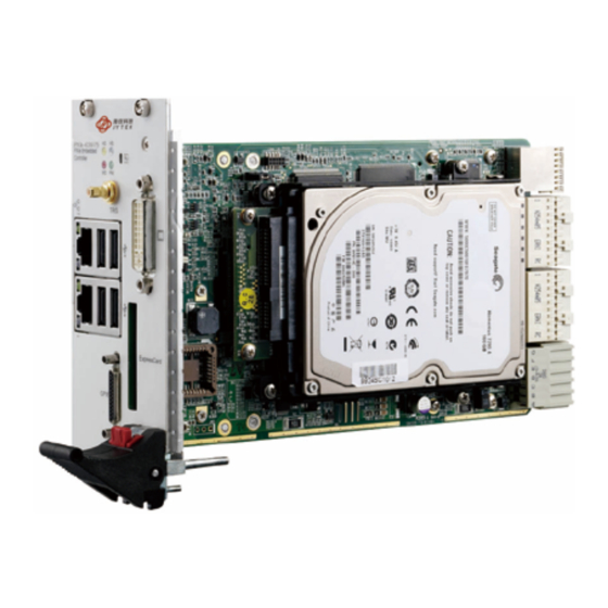
PXI Trigger Connector LED indicators (SMB jack) DVI-I Connector 4X Type-A USB connectors GPIB Connector 2X Gigabit Ethernet (Micro D-Sub 25P) Reset Button ExpressCard/34 2�3�2 PXI Trigger Connector Ground Trigger Figure 2-2: PXI Trigger SMB Jack The PXI trigger connector is a SMB jack, used to route external trigger signals to or from the PXI backplane. -
Page 15: 2�3�4 Gpib Connector
Signal Signal Signal Signal TMDS TMDS TMDS Analog Data1- Data2- Data0- TMDS TMDS TMDS Analog Data2+ Data1+ Data0+ Green Shield Shield Shield Analog Ground Ground Ground Blue Reserved 12 Reserved 20 Reserved C4 Analog HSYNC Reserved 13 Reserved 21 Reserved C5 Analog Ground DDC Clock 14... -
Page 16: Reset Button
Connection with up to 14 instruments Signal Description Signal Description DIO1# GPIB Data 1 DIO5# GPIB Data 5 DIO2# GPIB Data 2 DIO6# GPIB Data 6 DIO3# GPIB Data 3 DIO7# GPIB Data 7 DIO4# GPIB Data 4 DIO8# GPIB Data 8 End Or Identify Remote Enable Data Valid... -
Page 17: 2�3�7 Usb 2�0 Ports
In the event of malfunction, clear the CMOS (please see Section 2.3.15: Clearing CMOS Jumper (JP1)) and reboot the system. If the system fails to respond properly, please contact JYTEK for assistance. 2�3�7 USB 2�0 Ports The PXIe-63975 provides four USB 2.0 ports via USB Type A connectors on the faceplate, all compatible with hi-speed, full-speed and low-speed USB devices. -
Page 18: 2�3�8 Gigabit Ethernet Ports
2�3�8 Gigabit Ethernet Ports Two Intel 82574L GbE controllers via x1 PCI Express interface provide dual Gigabit Ethernet connectivity, with the upper connector supporting Wake-on-LAN function. 1000Base-T Signal 100/10Base-T Signal MDI0+ MDI0- MDI1+ MDI2+ Reserved MDI2- Reserved MDI1- MDI3+ Reserved MDI3- Reserved Table 2-5: PXIe-63975 Ethernet Port Pin Assignments... -
Page 19: 2�3�9 Expresscard/34
2�3�9 ExpressCard/34 The PXIe-63975 controller is equipped with an ExpressCard/34 slot on the front panel, which provides I/O expansion. ExpressCard connector signals are as follows. Signal Description Signal Description Ground +3.3V Power USBD- USB Data - +3.3V Power USBD+ USB Data + CLKREQ# Clock Request CPUSB#... -
Page 20: Onboard Connections And Settings
2�3�10 Onboard Connections and Settings Figure 2-4: PXIe-63975 Onboard Configuration SATA Connector JP1 (CMOS) System Battery While the PXIe-63975 ships with a 2.5” SATA hard drive pre-installed to the SATA port, no HDD is shown installed, for clarity. -
Page 21: Installation Environment
Anti-static wrist strap Anti-static mat JYTEK PXIe-63975 system controllers are electrostatically sensitive and can be easily damaged by static electricity. The equipment must be handled on a grounded anti-static mat, and operators must wear an anti-static wristband, grounded at the same point as the anti-static mat. -
Page 22: 2�3�12 Installing The Pxie-63975
2�3�12 Installing the PXIe-63975 1 Locate the system controller slot (Slot 1) 2 Depress the red locking lever and release the latch 3 Align the controller’s top and bottom edges with the card guides, and carefully slide the PXIe-63975 into the chassis, as shown 4 Elevate the latch until the PXIe-63975 is fully seated in the chassis backplane. - Page 23 3. Gently lift and remove the SATA hard drive, as shown,being careful to not bend o break the SATA Board-to-Board connector.
-
Page 24: Replacing The Battery Backup
4. To replace the HD with a solid state hard drive or other compatible SATA hard drive, reverse the steps and reinstall the PXIe-63975 to the PXI system. 2.3.14 Replacing the Battery Backup The PXIe-63975 is provided with a 3.0 V “coin cell” lithium battery. To replace the battery, proceed as follows. -
Page 25: Clearing Cmos Jumper (Jp1)
negative retaining clip. The battery should easily snap into position. 9. Replace the hard drive. 10. Reinstall the embedded controller into the PXIe chassis and restore power. 2.3.15 Clearing CMOS Jumper (JP1) In the event of a system malfunction causing the PXIe-63975 to halt or fail to boot, clear the CMOS and restore the controller BIOS to its default settings. -
Page 26: Driver Installation
• Identification of Intel® Chipset Components in the Device Manager To install the chipset driver: 1. Close any running applications 2. Insert the JYTEK All-in-One USB Flash Driver (x: denotes the USB driver) ◦ The WinXP chipset driver is located in the directory x:\Driver Installation\PXI Platform\PXI Controller\PXIe-63975\Chipset\WinXP\INF_Update_Utility ◦... -
Page 27: 3�4 Installing The Ethernet Driver
2. Insert the JYTEK All-in-One USB Flash Driver (x: denotes the USB driver) ◦ The WinXP VGA driver is located in the directory x:\Driver Installation\PXI Platform\PXI controller\PXIe-63975\WinXP\VGA ◦ The 32bit Win7 VGA driver is located in the directory x:\Driver Installation\PXI Platform\PXI controller\PXIe-63975\Win7_32Bit\VGA\ ◦... -
Page 28: Installing The Management Engine Driver
To install the management engine driver: 1. Close any running applications. 2. Insert the JYTEK All-in-One USB Flash Driver (x: denotes the USB driver) ◦ The WinXP ME driver is located in the directory x:\ Driver Installation\PXI Platform\PXI controller\PXIe-63975\ME\WinXP\Intel ME ◦... -
Page 29: Bios Setup
4 BIOS Setup The Basic Input/Output System (BIOS) provides a basic level of communication between the processor and peripherals. In addition, the BIOS also contains code for various advanced features applied to the PXIe-63975 controller. The BIOS setup program includes menus for configuring settings and enabling PXIe-63975 controller features. -
Page 30: 4�2 Main Setup
Key(s) Function <F2> Loads previous values into the BIOS <F3> Restores default values into the BIOS <F4> Saves the current configuration and exits BIOS setup <F9> Loads the optimal default BIOS settings Table 4-1: BIOS Hot Key Functions Figure 4-1: BIOS Setup Navigation A hot key legend is located in the right frame on most setup screens. -
Page 31: 4�3 Advanced Setup
Item Detail BIOS Information Includes BIOS version and the date on which the BIOS was built Memory Information Shows memory size, type and speed as detected by the BIOS ME Information Indicates the version of the management engine Board Information Such as hardware revisions and serial number System Date &... -
Page 32: Chipset Configuration
Item Detail Thermal Configuration Sets platform thermal configuration and Intelligent Power Sharing Temperature Monitor Shows the current operating temperature inside the controller. Table 4-3: BIOS Advanced Setup Menu 4�4 Chipset Configuration Item Detail North Bridge Configuration Provides memory and PCIe compliance information South Bridge Configuration Provides SMBus, GbE Controller, Wake on LAN, Audio, USB Configuration, and PCIe Port Configuration... -
Page 33: 4�7 Save & Exit Setup
or User) every time the system boots or when Setup is executed. Administrators and User passwords activate different levels of security. If passwords are used, the system prompts for a three- to twenty-character password. Typed passwords are not displayed. Item Details Password Description Administrator Password... -
Page 34: Appendix A - Pxi Trigger I/O Function Reference
PXI trigger bus on the backplane. A.1 Data Types The PXIe-63975 library uses these data types in pxitrigio.h in the directory X:\JYTEK\PXI Trigger IO\Include. It is recommended that you use these data types in your application programs. -
Page 35: Function Library
A.2 Function Library This section provides detailed definitions of the functions available in the PXIe-63975 function library. Each function includes a description, list of supported cards, syntax, parameter list and Return Code information. A�2�1 TRIG_Init Description Initializes trigger I/O function of PXIe-63975 controller. TRIG_Init must be called before the invocation of any other trigger I/O function. -
Page 36: Trig_Setsofttrg
None Return Code ERR_NoError ERR_BoardNoInit A�2�3 TRIG_SetSoftTrg Description Generates a TTL trigger signal to the trigger I/O SMB connector on the faceplate or the PXI trigger bus on the backplane by software command Supported Controllers PXIe-63975, PXI-63930, PXI-63980 Syntax C/C++ I16 TRIG_SetSoftTrg(U8 Status) Visual Basic TRIG_SetSoftTrg (ByVal status As Byte) As Integer... - Page 37 Visual Basic TRIG_Trigger_Route (ByVal source As Long, ByVal dest As Long, ByVal halfway As Long) As Integer Parameters source Source of trigger routing. It can be one of the following values Available value Description PXI_TRIG_VAL_SMB SMB connector on the faceplate PXI_TRIG_VAL_SOFT Software-generated trigger signal PXI_TRIG_VAL_TRIG0...
-
Page 38: A�2�5 Trig_Trigger_Clear
Available value Description PXI_TRIG_VAL_TRIG7 PXI trigger bus #7 Return Code ERR_NoError ERR_BoardNoInit ERR_Set_Path A�2�5 TRIG_Trigger_Clear Description Clears the trigger routing setting Supported Controllers PXIe-63975, PXI-63930, PXI-63980 Syntax C/C++ I16 TRIG_Trigger_Clear() Visual Basic TRIG_Trigger_Clear() As Integer Parameters None Return Code ERR_NoError ERR_BoardNoInit ERR_Trigger_Clr A�2�6 TRIG_GetSoftTrg... -
Page 39: Trig_Trigger_Route_Query
TRIG_GetSoftTrg (status As Byte) As Integer Parameters Status Returns the logic level of software trigger signal Returned value: 0: Logic low 1: Logic high Return Code ERR_NoError ERR_BoardNoInit ERR_Query_Status A.2.7 TRIG_Trigger_Route_Query Description Acquires the current trigger signal routing path Supported Controllers PXIe-63975, PXI-63930, PXI-63980 Syntax C/C++... -
Page 40: A�2�8 Trig_Getdriverrevision
dest Returns to the current destination of trigger routing, with possible values including: Available Definition Defined Value PXI_TRIG_VAL_NONE PXI_TRIG_VAL_SMB PXI_TRIG_VAL_TRIG0 PXI_TRIG_VAL_TRIG1 PXI_TRIG_VAL_TRIG2 PXI_TRIG_VAL_TRIG3 PXI_TRIG_VAL_TRIG4 PXI_TRIG_VAL_TRIG5 PXI_TRIG_VAL_TRIG6 PXI_TRIG_VAL_TRIG7 halfway Returns to the current halfway point of trigger routing, with possible values including: Available Value Description PXI_TRIG_VAL_NONE... -
Page 41: A�2�9 Controller_Gethwrevision
Visual Basic TRIG_GetDriverRevision (major As Integer, minor1 As Integer, minor2 As Integer) As Integer Parameters major Returns the major version number of the pxi trigger software driver minor1 Returns the first minor version number of the pxi trigger software driver minor2 Returns the second minor version number of the pxi trigger software driver Return Code... -
Page 42: A�2�10 Controller_Getmanufacturer
Return Code ERR_NoError ERR_InvalidParameterValue A�2�10 CONTROLLER_GetManufacturer Description Ascertains the hardware manufacturer Supported Controllers PXIe-63975 Syntax C/C++ I16 CONTROLLER_GetManufacturer( char* Buf, U32 Bufsize ) Visual Basic CONTROLLER_GetManufacturer (Buf As String, Bufsize As Long) As Integer Parameters Character buffer of size declared by the caller of size BufSize, returns a null-terminated string representation of the hardware manufacturer BufSize Size of the Buf, in bytes... -
Page 43: Controller_Getserialnumber
Parameters Character buffer of size declared by the caller of size BufSize, returns a null-terminated string representation of the hardware model name BufSize Size of the Buf, in bytes Return Code ERR_NoError ERR_InvalidParameterValue A.2.12 CONTROLLER_GetSerialNumber Description Acquires the serial number of the hardware Supported Controllers PXIe-63975 Syntax... -
Page 44: Appendix B - Watchdog Timer
Appendix B - Watchdog Timer This appendix describes use of the watchdog timer (WDT) function library for the PXIe- 63975 controller. The watchdog timer is a hardware mechanism resetting the system when the operating system or application halts. After starting, periodic reset of the watchdog timer in the application before expiry is required. -
Page 45: B�1�3 Startwdt
InitWDT(ByVal second as Long) As Boolean Parameter second Specifies the timeout value of the watchdog timer. Value Description Value Description 0 to 255 If the value of the second parameter is between 0 and 255, the resolution of the watchdog timer is 1 second Over 255 If the value of the second parameter exceeds 255, the resolution of the watchdog timer is 1 minute, that is, if a value of 400 is given,... -
Page 46: B�1�5 Stopwdt
ResetWDT or StopWDT should be called before the expiration of the watchdog timer, or the system will be reset. Supported Controllers PXIe-63975, PXI-63930, PXI-63980 Syntax C/C++ BOOL ResetWDT() Visual Basic ResetWDT() As Boolean Parameter None Return Code True If watchdog timer resets successfully False If watchdog timer fails to reset B�1�5 StopWDT... -
Page 47: Important Safety Instructions
Important Safety Instructions For user safety, please read and follow all instructions, WARNINGS, CAUTIONS, and NOTES marked in this manual and on the associated equipment before handling/operating the equipment. • Read these safety instructions carefully. • Keep this user’s manual for future reference. •...
Need help?
Do you have a question about the PXI Express PXIe-63975 and is the answer not in the manual?
Questions and answers