Advertisement
®
VEVOR
TOUGH TOOLS, HALF PRICE
Technical Support and E-Warranty Certificate www.vevor.com/support
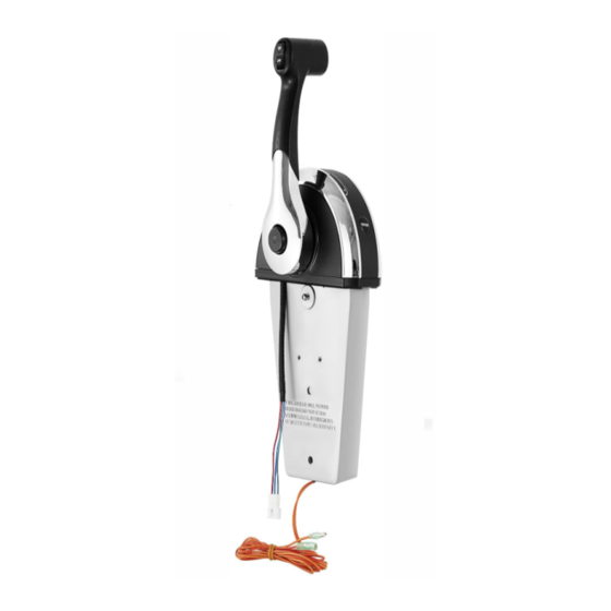
OUTBOARD REMOTE CONTROL BOX
8M0059686
MODEL:
We continue to be committed to provide you tools with competitive price.
"Save Half', "Half Price" or any other similar expressions used by us only represents an
estimate of savings you might benefit from buying certain tools with us compared to the major
top brands and does not necessarily mean to cover all categories of tools offered by us. You
are kindly reminded to verify carefully when you are placing an order with us if you are
actually saving half in comparison with the top major brands
Advertisement
Table of Contents

Subscribe to Our Youtube Channel
Related Manuals for VEVOR 8M0059686


Summary of Contents for VEVOR 8M0059686
- Page 1 ® VEVOR TOUGH TOOLS, HALF PRICE Technical Support and E-Warranty Certificate www.vevor.com/support OUTBOARD REMOTE CONTROL BOX 8M0059686 MODEL: We continue to be committed to provide you tools with competitive price. "Save Half', "Half Price" or any other similar expressions used by us only represents an estimate of savings you might benefit from buying certain tools with us compared to the major top brands and does not necessarily mean to cover all categories of tools offered by us.
- Page 3 This is the original instruction, please read all manual instructions carefully before operating. VEVOR reserves a clear interpretation of our user manual. The appearance of the product shall be subject to the product you received. Please forgive us that we won't inform you again if...
- Page 4 CONSOLE REMOTE CONTROL INSTALLATION AND OPERATION NOTICE After completing installation, place these instructions with the product for the owner's future use. NOTICE This document is written to aid our dealers, boatbuilders, and company service personnel in the proper installation or service of our products. Persons who are not familiar with these or similar products produced by Mercury Marine, and who have not been trained in the recommended servicing or installation procedures should have the work performed by an authorized Mercury Marine dealer technician.
-
Page 5: General Installation Information
CONSOLE REMOTE CONTROL INSTALLATION AND OPERATION Selecting GEN II Remote Control Cables Mercury - Mariner - Force - Mercury MerCruiser Refer to the Mercury Precision Parts Accessories Guide for the available shift and throttle cables for your application. This control requires the use of Mercury/Quicksilver GEN II shift and throttle cables. IMPORTANT: Remote control cables must be the correct length. - Page 6 CONSOLE REMOTE CONTROL INSTAL凶TION AND OPERATION Reinstallation of Control Handle Improper installation can result in sudden, unexpected loss of throttle and shift control, resulting in serious injury or death. Install all control components property. If the control handle is removed and reinstalled for any reason, apply Loctite 271 Thread locker on the threads of the control handle retaining bolt.
- Page 7 CONSOLE REMOTE CONTROL INSTALLATION AND OPERATION : N ING Performing tests with the engine running may cause the propeller to rotate and result in serious injury or death. Use caution when performing a test that requires the engine running, and remove the propeller to avoid injury. Check the operation of the neutral start safety switch.
- Page 8 CONSOLE REMOTE CONTROL INSTALLATION AND OPERATION IMPORTANT: Allow sufficient clearance for the handle movement to avoid interference with boat components or other accessories. Ensure the control handle clears the dash, seats, steering wheel, and any other obstructions when rotating the control handle.
- Page 9 CONSOLE REMOTE CONTROL INSTALLATION AND OPERATION Shift and Throttle Cable Installation Control Cable Anchor Attaching Location Starboard Mount Control Port Mount Control Anchor Attaching Anchor Attaching Outboard Models (U.S. and Belgium Models Only) Location Location Throttle Throttle Shift Cable Shift Cable Cable Cable Force Outboards (except 9.9 and 15)
- Page 10 CONSOLE REMOTE CONTROL INSTALLATION AND OPERATION Remove the screws securing the back plate to the control module. ',;Ill<" 乓 ) a - Back plate b - Washer c - Screw (5) 17557 IMPORTANT: Determine the type of drive unit rotation the cable is installed onto. The shift cable must be correctly installed at the remote control assembly for the appropriate drive unit rotation;...
- Page 11 CONSOLE REMOTE CONTROL INSTALLATION AND OPERATION Tighten the cable fastener screws to the specified to「que. a - Small spacer b- Screw C - Shift cable d - Throttle cable e - Large spacer Tube Ref No. Description Part No Loctite 271 Threadlocker Control cable crew threads 92-809819...
-
Page 12: Mounting The Remote Control
CONSOLE REMOTE CONTROL INSTALLATION AND OPERATION Description lb-in. lb-f t Back plate SC「ews (5) Mounting the Remote Control Single Handle Console Control Models NOTE·The gasket and mounting base must be placed over the console control mount opening prior to installi n g the sh竹and throttle cables to the control module. - Page 13 CONSOLE REMOTE CONTROL INSTALLATION AND OPERATION Turn the control friction adjustment nut counte「clockwise to decrease the resistance Install a cable tie anchor onto the mounting screw located at the right side of the handle. Secure the remote control module assembly to the console with four mounting screws 38 mm (1.5 in.). Tighten the screws securely.
-
Page 14: Wire Color Code Abbreviations
CONSOLE REMOTE CONTROL INSTALLATION AND OPERATION Hook the rear of the cover into the base and fasten the f「ont of the cover to the base with a screw. Tighten the screw securely. a - Cover b - Screw 10. Connect the remote control neutral start safety switch leads to the correct wire connections. Refer to Wiring Diagrams. Starting the engine with the drive in gear can cause serious injury or death. -
Page 15: Wiring Diagrams
CONSOLE REMOTE CONTROL INSTALLATION AND OPERATION Wiring Diagrams Single Outboard 歹 � 一门 a - 14-pin connecto「 b - Ignition key switch c - Lanyard connection for MCM models d - Power trim connector e - Neutral start safety switch leads f - Analog gauge harness... - Page 16 CONSOLE REMOTE CONTROL INSTALLATION AND OPERATION Single Mercury MerCruiser - Gasoline Models 了 c1I( � 值 a - 14-pin connector b - Ignition key switch c - Lanyard connection for MCM models d - Trim limit switch e - Power trim harness connector f - Neutral start safety switch leads g - Analog gauge harness...
- Page 17 CONSOLE REMOTE CONTROL INSTALLATION AND OPERATION Single Mercury MerCruiser - Diesel Models D3.0L/150, D3.6L/180, D4.2L/220 RED/PUR 丘 。 PUR - YEUREC BLK/YEL 江 BLK/YEL 品 丐 ? 笆 � G R : 三 一 三 二 二 :; 三 .--CD �...
- Page 18 CONSOLE REMOTE CONTROL INSTALLATION AND OPERATION Single Mercury MerCruiser- Diesel Model D7.3U270 『 ” 。 。 (QJD仁二二} Y EL/RED - YEL/RED --= YEURED � G R : 三 二 二三 BL U芒二 a - 12 volt source b - Lanyard stop switch leads c - Lanyard stop switch d - Water in fuel indicator e - Coolant temperature indicator...
-
Page 19: Features And Operation
CONSOLE REMOTE CONTROL INSTALLATION AND OPERATION Features and Operation Power trim switch (if equipped) - Used to trim or raise drive unit for trailering, launching, beaching, or shallow water operation. Refer to the Operation and Maintenance Manual for detailed power trim/tilt operating procedures. Trailer switch (if equipped) - Used to raise the drive unit beyond the maximum trim position. - Page 20 CONSOLE REMOTE CONTROL INSTALLATION AND OPERATION 一 \ 、 』 \ / . 于 , 88.9 mm (3-1/2 in.) \ \ 、一一一一一一一一/ 67.3 mm (2-21/32 in.) a- F「ont of boat b - Drill to the co「rect diameter for the fasteners used Alpha, 沁cius, Bravo One, Bravo Two, Bravo Three, C四e M with Waves Logo, K-planes, Mariner, MerCathode, Products of Mercury Marine MerCruiser, Mercury, Mercury wilh Waves Logo, Mercury Marine, Mercury Precision Parts, Mercury Propellers...
- Page 21 Components Picture Screw(M5*55) Nut(M5) Rubber sleeve and screw(M5*40) Screw(M4*8) Washer Screw(M4*7) Plug Insulated terminal sleeve 1 Insulated terminal sleeve 2 Terminal(Male a18nd female) Tie holder Cable tie holder 1 Cable tie holder 2 Cable tie Mounting bracket Cover Decorative seat Rubber buckle Use Manual...
-
Page 22: Correct Disposal
CORRECT DISPOSAL This product is subject to the provision of european Directive 2012 /19/EU. The symbol showing a wheelie bin crossed through indicates that the product requires separate refuse collection in the European Union. This applies to the product and all accessories marked with this symbol.
Need help?
Do you have a question about the 8M0059686 and is the answer not in the manual?
Questions and answers