Table of Contents
Advertisement
Available languages
Available languages
Quick Links
Technical Support and E-Warranty Certificate www.vevor.com/support
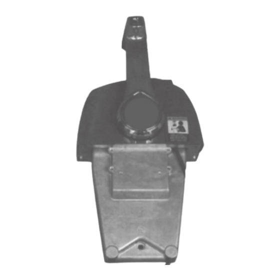
O U T B O A R D R E M O T E C O N T R O L B O X
M O D E L :5006186
We continue to be committed to provide you tools with competitive price.
"Save Half", "Half Price" or any other similar expressions used by us only represents an
estimate of savings you might benefit from buying certain tools with us compared to the major
top brands and does not necessarily mean to cover all categories of tools offered by us. You
are kindly reminded to verify carefully when you are placing an order with us if you are
actually saving half in comparison with the top major brands.
Advertisement
Table of Contents

Related Manuals for VEVOR 5006186


Summary of Contents for VEVOR 5006186
- Page 1 O U T B O A R D R E M O T E C O N T R O L B O X M O D E L :5006186 We continue to be committed to provide you tools with competitive price.
- Page 3 .vev o r.co m /su p p o rt This is the original instruction, please read all manual instructions carefully before operating. VEVOR reserves a clear interpretation of our user manual. The appearance of the product shall be subject to the product you received.
-
Page 4: Safety Information
BINNACLE MOUNT REMOTE CONTROL INSTALLATION AND USER'S GUIDE Always follow common shop safety practices. If APPLICATION you have not had training re l ated t o common ™· ® bin n acle mount re- Use fo『"Evinrude E-TEC shop safety practices, you should do so to pr o mote control assemblies designed for Evinrude ®... - Page 5 CONTENTS OF KITS - BINNACLE MOUNT REMOTE CONTROL Single Lever Binnacle (with keyswitch) PN 5006186...
-
Page 7: Remote Control Operation
Fast Idle REMOTE CONTROL OPERATION Use of fast idle feature is not required on Read and familiarize yourself with the complete Evinrude E-TEC outboards. Refer to operator's operation of the remote control before attempting guide for specific outboard. to start the outboard The fast idle button can be used to advance IMPORTANT: The operation of this remote con... -
Page 9: Installation Instructions
Refer to "SINGLE LEVER BINNACLE MOUNT INSTALLATION INSTRUCTIONS REMOTE CONTROL PR OFI LE DIMENSIO NS" on page 15 and "DUAL LEVER BINNAC L E Read and familiarize yourself with the complete installation instructions of the remote control MOUNT REMOTE CONTROL PROFILE before attempting to install the remote control. - Page 10 Determine Remote Control Cable Length Cut Mountin g Holes Refer to profile drawings and use appropriate Measure from center of control handle with drill template to cut mounting holes. remote control in mounting position, alo ng intended cable route to engine centerline at IMPORTANT: Make sure the mounting location transom height as illustrated by dotted lines in diagram.
- Page 11 Install Remote Control Cables Remove friction cover. Remove cover retaining Remove screws and side cover from remote screw(s) and remote control cove「. Single Lever Remote Control Single Lever Remote Control (with key switch) 1. Screw cover 1. Side Remove flange retainer screws and flange. Install shift cable and flat washer on t o s h i ft pinand secure with new cotter pin.
- Page 12 Always use new cotter pins and bend both sides of cotter pin as shown to prevent interference with remote control housing or possible dislodging of cotter pin from mounitng pin. Make sure shift and throttle cables are in trunnion pocket(s), and saftey switch wiring does not rub or interfere with movements of remote control components.
- Page 13 REMOTE CONTROL OPERATION TEST NEUTRAL START TEST CAUTION Operation Tests must be performed with Make certain starter will not operate when outboard stopped. Disconnect emergency the outboard is in gear. The start-in-gear stop lanyard, disconnect battery cables, prevention feature is required by the and remove spark plug wires from spark United States Coast Guard to help prevent plugs and/or disconnect crankshaft posi一...
-
Page 14: Emergency Stop Switch Test
EMERGENCY STOP SWITCH TEST OPERATOR TESTS AND ADJUSTMENTS IMPORTANT: Test operation of emergency stop switch at each outing. Refer to EMERGEN CY STOP SWITCH TEST. If outboa d does not Always use the safety lanyard when oper 「 stop, return control to dealer for repair. ating boat to help prevent a runaw ay boat Check throttle friction. -
Page 15: Maintenance
Use Triple-Guard grease to lubricate all moving MAINTENANCE mechanisms and remote control cables . CAUTION Inspection and maintenance must be per formed with outboard i;topped. Disconnect emergency stop lanyard, disconnect bat tery cables, and remove spark plug wires from spark plugs and/or disconnect crank shaft position sensor (CPS) connector to prevent accidental starting of outboard. - Page 16 SINGLE LEVER BINNACLE MOUNT REMOTE CONTROL PROFILE DIMENSIO NS f<Y 。 , , 趴 七 430mm I 16.91n. 七 194mm / 7.6in.
-
Page 17: Drill Template
DRILL TEMPLATE Single Lever Binnacle Mount Remote Contr ol 57mm I 2.24 In. 令 4-R3 上 , ' , 令 \ / ' , . · u · u � · 9 , , ' , , ' , \ � :... -
Page 18: Correct Disposal
CORRECT DISPOSAL This product is subject to the provision of european Directive 2012 /19/EU. The symbol showing a wheelie bin crossed through indicates that the product requires separate refuse collection in the European Union. This applies to the product and all accessories marked with this symbol. - Page 20 Tech n ical S u p p o rt an d E -W arran ty C ertifica te w w w .vev o r.co m /su p p o rt...
- Page 21 Machine Translated by Google Assistance t echnique e t c ertificat d e g arantie é lectronique w ww.vevor.com/support BOÎTIER D E T ÉLÉCOMMANDE H ORSBORD MODÈLE : 5 006186 Nous c ontinuons à n ous e ngager à v ous f ournir d es o utils à d es p rix c ompétitifs.
- Page 22 Machine Translated by Google...
- Page 23 Assistance t echnique e t c ertificat d e g arantie électronique w ww .vevor.com/support Il s 'agit d es i nstructions o riginales, v euillez l ire a ttentivement t outes l es i nstructions d u ...
- Page 24 Machine Translated by Google GUIDE D 'INSTALLATION E T D 'UTILISATION D E L A T ÉLÉCOMMANDE À MONTAGE B INNACLE S uivez t oujours l es p ratiques d e s écurité c ourantes APPLICATION en a telier. S i v ous n 'avez p as s uivi d e f ormation s ur l es p ratiques ™∙...
- Page 25 Machine Translated by Google CONTENU D ES K ITS T ÉLÉCOMMANDE P OUR M ONTAGE H ABITACLE Habitacle à l evier u nique ( avec i nterrupteur à c lé) P N 5 006186...
- Page 26 Machine Translated by Google CARACTÉRISTIQUES D E L A T ÉLÉCOMMANDE À M ONTAGE H ABITACLE 1. I nterrupteur d e t rim e t d'inclinaison 2 . P oignée, l evier d e vitesse e t a ccélérateur 3 . ...
- Page 27 Machine Translated by Google Ralenti r apide FONCTIONNEMENT D E L A T ÉLÉCOMMANDE L'utilisation d e l a f onction d e r alenti r apide n 'est p as r equise s ur l es Lisez e t f amiliarisezvous a vec l e f onctionnement c omplet d e l a horsbord ...
- Page 28 Machine Translated by Google...
-
Page 29: Instructions D'installation
Machine Translated by Google Reportezvous a ux s ections « DIMENSIONS D U P ROFIL D E INSTRUCTIONS D 'INSTALLATION TÉLÉCOMMANDE À M ONTAGE S UR H ABITACLE À L EVIER Lisez e t f amiliarisezvous a vec l es i nstructions d 'installation UNIQUE » ... - Page 30 Machine Translated by Google Déterminer l a l ongueur d u c âble d e l a t élécommande Découper l es t rous d e Mesurez à p artir d u c entre d e l a p oignée d e c ommande a vec montage ...
- Page 31 Machine Translated by Google Installer l es c âbles d e t élécommande Retirez l es v is e t l e c ouvercle l atéral d e télécommande Retirez l e c ouvercle d e f riction. R etirez l a o u l es v is d e r etenue d u c ouvercle et ...
- Page 32 Machine Translated by Google Fixez l a t élécommande a u b ateau Fixez l e b oîtier d e c ommande e n p osition a vec l es v is d e m ontage f ournies. Utilisez t oujours d e n ouvelles g oupilles f endues e t p liez l es d eux c ôtés Installez ...
- Page 33 Machine Translated by Google TEST D E F ONCTIONNEMENT D E L A T ÉLÉCOMMANDE TEST D E D ÉMARRAGE N EUTRE PRUDENCE Un j e Les t ests d e f onctionnement d oivent ê tre e ffectués a vec l e Assurezvous ...
- Page 34 Machine Translated by Google TESTS E T R ÉGLAGES O PÉRATEUR TEST D E L 'INTERRUPTEUR D 'ARRÊT D 'URGENCE IMPORTANT : Testez l e f onctionnement d e l 'interrupteur d 'arrêt d'urgence à c haque s ortie. V oir T EST D E L 'INTERRUPTEUR D'ARRÊT ...
-
Page 35: Entretien
Machine Translated by Google ENTRETIEN Utilisez l a g raisse T ripleGuard p our l ubrifier t ous l es m écanismes mobiles e t c âbles d e t élécommande. Un j e PRUDENCE L'inspection e t l 'entretien d oivent ê tre e ffectués a vec l e moteur ... - Page 36 Machine Translated by Google DIMENSIONS D U P ROFIL D E L A T ÉLÉCOMMANDE À M ONTAGE S UR H ABITACLE À L EVIER U NIQUE f<Y. 210,4 m m 8,3 p ouces Allongezvous, s ept NEUTRE 430 ...
- Page 37 Machine Translated by Google MODÈLE D E F ORAGE Télécommande à m ontage s ur h abitacle à l evier u nique 57 m m e t 2 ,24 p ouces. faire faire 4R3 Debout, j e en 1 u1 6 5991 ...
- Page 38 Machine Translated by Google ÉLIMINATION C ORRECTE Ce p roduit e st s oumis a ux d ispositions d e l a d irective e uropéenne 2 012 /19/UE. L e s ymbole r eprésentant u ne p oubelle b arrée i ndique q ue l e p roduit nécessite ...
- Page 39 Machine Translated by Google...
- Page 40 Machine Translated by Google Support t echnique e t c ertificat d e g arantie E W www.vevor.com /support...
- Page 41 Machine Translated by Google Technischer Support und E-Garantiezertifikat www.vevor.com/support AUSSENBORD-FERNBEDIENUNGSKASTEN MODELL:5006186 Wir sind weiterhin bestrebt, Ihnen Werkzeuge zu wettbewerbsfähigen Preisen anzubieten. „Sparen Sie die Hälfte“, „Halber Preis“ oder andere ähnliche von uns verwendete Ausdrücke stellen lediglich eine Schätzung der Einsparungen dar, die Sie durch den Kauf bestimmter Werkzeuge bei uns im Vergleich zu den großen Top-Marken erzielen könnten, und bedeuten nicht unbedingt, dass alle angebotenen Werkzeugkategorien...
- Page 42 Machine Translated by Google...
- Page 43 .vevor.com/support Dies ist die Originalanleitung. Bitte lesen Sie alle Bedienungsanleitungen sorgfältig durch, bevor Sie das Gerät in Betrieb nehmen. VEVOR behält sich eine klare Auslegung unserer Bedienungsanleitung vor. Das Aussehen des Produkts hängt von dem Produkt ab, das Sie erhalten haben.
- Page 44 Machine Translated by Google BINNACLE MOUNT FERNBEDIENUNG – INSTALLATIONS- UND BENUTZERHANDBUCH Befolgen Sie stets die üblichen Sicherheitspraktiken in der Werkstatt. Wenn Sie keine ANWENDUNG Schulung zu allgemeinen Sicherheitspraktiken in Geschäften erhalten ™· ® haben, sollten Sie dies tun, um sich selbst und die Menschen in Ihrer Verwenden Sie für „Evinrude E-TEC Binnacle Mount Re- Umgebung zu schützen...
- Page 45 Machine Translated by Google INHALT DER KITS – FERNBEDIENUNG ZUR BINNACLE-MONTAGE Einhebel-Binnacle (mit Schlüsselschalter) PN 5006186...
- Page 46 Machine Translated by Google FUNKTIONEN DER BINNACLE-MONTAGE-FERNBEDIENUNG 1. Trimm- und Neigungsschalter 2. Griff, Schalt- und Gashebel 3. Schlüsselschalter (einschließlich Clip und Lanyard-Baugruppe) 4. Einstellschraube, Fernbedienungshebel-Reibung Schnellleerlauftaste Liste zusätzlicher Funktionen NACH VORNE • Neutrale Rastung • Schalter „Start-in-Gang-Verhinderung“. • Einstellbare Gasreibung •...
- Page 47 Machine Translated by Google BETRIEB MIT FERNBEDIENUNG Schneller Leerlauf Bei Evinrude E-TEC-Außenbordmotoren ist die Verwendung der Lesen und machen Sie sich mit der vollständigen Bedienung der Schnellleerlauffunktion nicht erforderlich. Informationen zum jeweiligen Fernbedienung vertraut, bevor Sie versuchen, den Außenborder Außenbordmotor finden Sie in der Bedienungsanleitung. zu starten Mit der Schnellleerlauftaste können Sie Gas geben, ohne einen WICHTIG: Die Bedienung dieser Fernbedienung kann je nach...
- Page 48 Machine Translated by Google...
- Page 49 Machine Translated by Google Siehe „ABMESSUNGEN DES EINHEBEL- INSTALLATIONSANLEITUNG FERNBEDIENUNGSPROFILS FÜR DIE MONTAGE DER Lesen und machen Sie sich mit der vollständigen FERNBEDIENUNG“ auf Seite 15 und „ABMESSUNGEN DES Installationsanleitung der Fernbedienung vertraut, bevor Sie FERNBEDIENUNGSPROFILS FÜR DIE MONTAGE DES versuchen, die Fernbedienung zu installieren.
- Page 50 Machine Translated by Google Bestimmen Sie die Länge des Fernbedienungskabels Montagelöcher ausschneiden. Messen Sie von der Mitte des Steuergriffs mit der Fernbedienung in Sehen Sie sich die Profilzeichnungen an und verwenden Sie eine geeignete Bohrschablone, um Montagelöcher zu schneiden. Montageposition entlang der vorgesehenen Kabelführung bis zur Mittellinie des Motors auf Spiegelhöhe, wie durch die gestrichelten WICHTIG: Stellen Sie vor dem Bohren oder Schneiden sicher, dass am Linien im Diagramm dargestellt.
- Page 51 Machine Translated by Google Installieren Sie Fernbedienungskabel Entfernen Sie die Schrauben und die Seitenabdeckung Fernbedienung Reibdeckel entfernen. Entfernen Sie die Befestigungsschraube(n) der Abdeckung und die Abdeckung der Fernbedienung. Hebel Fernbedienung Single Einhebelfernbedienung (mit Schlüsselschalter) 1. Schraube Abdeckung 1. Seite Flanschbefestigungsschrauben und Flansch entfernen. Bringen Sie das Schaltkabel und die Unterlegscheibe am Schaltstift an und sichern Sie es mit einem neuen Splint.
- Page 52 Machine Translated by Google Befestigen Sie die Fernbedienung am Boot Befestigen Sie den Steuerkasten mit den mitgelieferten Verwenden Sie immer neue Splinte und biegen Sie beide Seiten Befestigungsschrauben. Bringen Sie die Dichtung und die vier Schrauben an. des Splints wie gezeigt, um eine Behinderung des Befestigungsschrauben festziehen.
- Page 53 Machine Translated by Google FUNKTIONSTEST DER FERNBEDIENUNG NEUTRALSTARTTEST VORSICHT Betriebstests müssen bei gestopptem Außenborder durchgeführt Stellen Sie sicher, dass der Anlasser nicht funktioniert, wenn am werden. Trennen Sie die Notstoppleine, trennen Sie die Außenbordmotor ein Gang eingelegt ist. Die Funktion zur Batteriekabel und entfernen Sie die Zündkerzenkabel von den Verhinderung des Anfahrens bei eingelegtem Gang wird von der Zündkerzen und/oder trennen Sie die Kurbelwellenposition...
- Page 54 Machine Translated by Google BEDIENERTESTS UND -ANPASSUNGEN NOT-AUS-SCHALTER-TEST WICHTIG: Testen Sie bei jedem Ausflug die Funktion des Not-Aus- Schalters. Siehe NOT-AUS-SCHALTER-TEST. Wenn der Außenbordmotor nicht stoppt, geben Sie die Steuerung zur Reparatur Benutzen Sie bei der Bedienung des Bootes immer die an den Händler zurück.
-
Page 55: Wartung
Machine Translated by Google WARTUNG Verwenden Sie Triple-Guard-Fett, um alle beweglichen Mechanismen und Fernbedienungskabel zu schmieren. VORSICHT Inspektionen und Wartungsarbeiten müssen bei abgedecktem Außenbordmotor durchgeführt werden. Trennen Sie die Notstoppleine, trennen Sie die Batteriekabel und entfernen Sie die Zündkerzenkabel von den Zündkerzen und/oder trennen Sie den Stecker des Kurbelwellen-Positionssensors (CPS), um ein versehentliches Starten des Außenborders zu verhindern. - Page 56 Machine Translated by Google ABMESSUNGEN DES EINHEBEL-BINNACLE-MONTAGE-FERNBEDIENUNGSPROFILS f<Yÿ 210,4 mm 8,3 Zoll Leg dich hin, sieben NEUTRAL 430mm I 16,91n. sieben o 862mm 227mm 3,4 Zoll 48 Zoll 194 mm / 7,6 Zoll.
- Page 57 Machine Translated by Google BOHRSCHABLONE Einhebel-Fernbedienung für Binnacle-Montage 57 mm I 2,24 Zoll. 4-R3 machen machen Auf, ich ÿÿ1 ',ÿ, ÿ ,ÿ, in 1 u1ÿ6 5991 ,9IEE 'llllll', EEOLL ÿ ',ich,'ich_ ÿÿ ÿÿ ',ICH \ÿ i machen: ÿ ICH., -----------—-+----- —-- —...
- Page 58 Machine Translated by Google RICHTIGE ENTSORGUNG Dieses Produkt unterliegt den Bestimmungen der europäischen Richtlinie 2012 /19/EU. Das Symbol mit der durchgestrichenen Mülltonne weist darauf hin, dass das Produkt einer getrennten Müllsammlung im Mülleimer bedarf Europäische Union. Dies gilt für das Produkt und alle Zubehörteile, die mit diesem Symbol gekennzeichnet sind.
- Page 59 Machine Translated by Google...
- Page 60 Machine Translated by Google Technischer Support und EW-Garantiezertifikat www.vevor.com/support...
- Page 61 Machine Translated by Google Supporto tecnico e certificato di garanzia elettronica www.vevor.com/support SCATOLA TELECOMANDO FUORIBORDO MODELLO:5006186 Continuiamo a impegnarci per fornirvi strumenti a prezzi competitivi. "Risparmia la metà", "Metà prezzo" o qualsiasi altra espressione simile da noi utilizzata rappresenta solo una stima del risparmio che potresti trarre dall'acquistare determinati strumenti con noi rispetto ai principali marchi più...
- Page 62 Machine Translated by Google...
- Page 63 .vevor.com/support Queste sono le istruzioni originali, leggere attentamente tutte le istruzioni del manuale prima dell'uso. VEVOR si riserva una chiara interpretazione del nostro manuale d'uso. L'aspetto del prodotto sarà soggetto al prodotto ricevuto. Ti preghiamo di perdonarci se non ti...
-
Page 64: Informazioni Sulla Sicurezza
Machine Translated by Google INSTALLAZIONE DEL TELECOMANDO PER MONTAGGIO A CHIESETTA E GUIDA PER L'UTENTE Seguire sempre le comuni pratiche di sicurezza in negozio. Se APPLICAZIONE non hai seguito una formazione relativa alle pratiche comuni di ™· ® sicurezza in negozio, dovresti farlo per proteggere te stesso e le Utilizzare per il supporto per chiesuola Evinrude E-TEC persone intorno a te gruppi di controllo remoto progettati per... - Page 65 Machine Translated by Google CONTENUTO DEI KIT - TELECOMANDO PER MONTAGGIO A CHIESETTA Chiesuola a leva singola (con interruttore a chiave) PN 5006186...
- Page 66 Machine Translated by Google CARATTERISTICHE DEL TELECOMANDO CON MONTAGGIO A CHIESETTA 1. Interruttore di assetto e inclinazione 2. Maniglia, cambio e acceleratore 3. Interruttore a chiave (incluso gruppo clip e cordino) 4. Vite di regolazione frizione leva telecomando 5. Tasto minimo veloce Elenco delle funzionalità...
- Page 67 Machine Translated by Google Minimo veloce FUNZIONAMENTO DA TELECOMANDO L'uso della funzione di minimo veloce non è richiesto sui fuoribordo Leggere e familiarizzare con il funzionamento completo del Evinrude E-TEC. Fare riferimento alla guida dell'operatore per il telecomando prima di tentare di avviare il fuoribordo fuoribordo specifico.
- Page 68 Machine Translated by Google...
-
Page 69: Istruzioni Per L'installazione
Machine Translated by Google Fare riferimento a "DIMENSIONI DEL PROFILO DEL ISTRUZIONI PER L'INSTALLAZIONE TELECOMANDO CON MONTAGGIO A CHIESETTA A LEVA Leggere e familiarizzare con le istruzioni complete di SINGOLA" a pagina 15 e "DIMENSIONI DEL PROFILO DEL installazione del telecomando prima di tentare di installare il TELECOMANDO CON MONTAGGIO A CHIESETTA A telecomando. - Page 70 Machine Translated by Google Tagliare i fori di montaggio Determinare la lunghezza del cavo del telecomando Misurare dal centro della leva di comando con il telecomando in Fare riferimento ai disegni del profilo e utilizzare la dima di foratura adeguata per tagliare i fori di montaggio. posizione di montaggio, lungo il percorso previsto del cavo fino alla linea centrale del motore all'altezza dello specchio di poppa, come IMPORTANTE: assicurarsi che la posizione di montaggio disponga...
- Page 71 Machine Translated by Google Installare i cavi del telecomando Rimuovere le viti e il coperchio laterale a distanza Rimuovere la copertura dell'attrito. Rimuovere le viti di fissaggio del coperchio e la copertura del telecomandoÿ. Leva del telecomando singola Telecomando a leva singola (con interruttore a chiave) 1.
- Page 72 Machine Translated by Google Fissare il telecomando all'imbarcazione Fissare la scatola di controllo in posizione con le viti di Utilizzare sempre coppiglie nuove e piegare entrambi i lati montaggio fornite. Installare la guarnizione e le quattro viti. della coppiglia come mostrato per evitare interferenze con Stringere le viti di montaggio.
- Page 73 Machine Translated by Google PROVA DI FUNZIONAMENTO DEL TELECOMANDO PROVA AVVIAMENTO IN FOLLE ATTENZIONE UN Io Le prove di funzionamento devono essere eseguite con il Assicurarsi che il motorino di avviamento non funzioni quando il fuoribordo fermo. Scollegare il cordino di arresto di emergenza, fuoribordo è...
- Page 74 Machine Translated by Google TEST E REGOLAZIONI DELL'OPERATORE PROVA DELL'INTERRUTTORE DI ARRESTO DI EMERGENZA IMPORTANTE: testare il funzionamento dell'interruttore di arresto di emergenza ad ogni uscita. Fare riferimento a TEST DELL'INTERRUTTORE DI ARRESTO DI EMERGENZA. Se il fuoribordo Utilizzare sempre il cordino di sicurezza durante la guida non si ferma, restituire il controllo al concessionario per la riparazione.
-
Page 75: Manutenzione
Machine Translated by Google MANUTENZIONE Utilizzare grasso Triple-Guard per lubrificare tutti i meccanismi mobili e i cavi del telecomando. ATTENZIONE UN Io L'ispezione e la manutenzione devono essere eseguite con il fuoribordo i;top. Scollegare il cordino di arresto di emergenza, scollegare i cavi della batteria e rimuovere i cavi delle candele dalle candele e/o scollegare il connettore del sensore di posizione dell'albero motore (CPS) per evitare l'avvio... - Page 76 Machine Translated by Google DIMENSIONI DEL PROFILO DEL TELECOMANDO A LEVA SINGOLA CON MONTAGGIO A CHIESELLA f<Yÿ 210,4 mm 8,3 pollici Sdraiati ,,, sette NEUTRO 430mm I 16.91n. sette o 862mm 227mm 3,4 pollici 48 pollici 194 mm/7,6 pollici...
- Page 77 Machine Translated by Google DIMA DI FORATURA Telecomando con montaggio a chiesuola a leva singola 57 mm e 2,24 pollici. Fare 4-R3 Fare Su, io ÿ,1 ',ÿ, ÿ ,ÿ, in 1 u1ÿ6 5991 ,9IEE "llllll", EEOLL ÿ ', io,' io_ ÿ...
-
Page 78: Corretto Smaltimento
Machine Translated by Google CORRETTO SMALTIMENTO Questo prodotto è soggetto alle disposizioni della Direttiva europea 2012 /19/UE. Il simbolo del bidone della spazzatura barrato indica che il prodotto necessita della raccolta differenziata dei rifiuti Unione Europea. Ciò vale per il prodotto e tutti gli accessori contrassegnati da questo simbolo. - Page 79 Machine Translated by Google...
- Page 80 Machine Translated by Google Supporto tecnico e certificato di garanzia EW www.vevor.com /support...
- Page 81 Machine Translated by Google Soporte t écnico y c ertificado d e g arantía e lectrónica w ww.vevor.com/support CAJA D E C ONTROL R EMOTO F UERA D E B ORDA MODELO:5006186 Seguimos c omprometidos a p roporcionarle h erramientas a p recios c ompetitivos.
- Page 82 Machine Translated by Google...
- Page 83 Soporte t écnico y c ertificado d e g arantía e lectrónica www .vevor.com/support Estas s on l as i nstrucciones o riginales; l ea a tentamente t odas l as i nstrucciones del m anual a ntes d e o perar. V EVOR s e r eserva u na i nterpretación c lara d e n uestro ...
- Page 84 Machine Translated by Google INSTALACIÓN D EL C ONTROL R EMOTO D E M ONTAJE E N B INNACLE Y G UÍA DEL U SUARIO S iga s iempre l as p rácticas d e s eguridad c omunes e n e l t aller. SOLICITUD Si ...
- Page 85 Machine Translated by Google CONTENIDO D E L OS K ITS M ANDO A D ISTANCIA D E M ONTAJE P ARA B INNACLE Bitácora d e p alanca ú nica ( con i nterruptor d e l lave) P N 5 006186...
- Page 86 Machine Translated by Google CARACTERÍSTICAS D EL C ONTROL R EMOTO D E M ONTAJE E N B ITÁCULA 1. I nterruptor d e compensación e i nclinación 2 . Manija, c ambio y a celerador 3 . I nterruptor d e l lave ( incluye c onjunto d e c lip y c ordón) 4. ...
- Page 87 Machine Translated by Google OPERACIÓN P OR C ONTROL R EMOTO Inactivo r ápido No s e r equiere e l u so d e l a f unción d e r alentí r ápido e n l os Lea y f amiliarícese c on e l f uncionamiento c ompleto d el c ontrol fuerabordas ...
- Page 88 Machine Translated by Google...
- Page 89 Machine Translated by Google Consulte " DIMENSIONES D EL P ERFIL D EL C ONTROL INSTRUCCIONES D E I NSTALACIÓN REMOTO D E M ONTAJE D E B ITÁCULA D E U NA P ALANCA" Lea y f amiliarícese c on l as i nstrucciones d e i nstalación en ...
- Page 90 Machine Translated by Google Corte l os o rificios d e m ontaje Determinar l a l ongitud d el c able d el c ontrol r emoto Mida d esde e l c entro d e l a m anija d e c ontrol c on e l c ontrol Consulte ...
- Page 91 Machine Translated by Google Instalar c ables d e c ontrol r emoto Retire l os t ornillos y l a c ubierta l ateral d e remoto Retire l a c ubierta d e f ricción. R etire l os t ornillos d e r etención d e l a cubierta ...
- Page 92 Machine Translated by Google Fije e l c ontrol r emoto a l b arco Fije l a c aja d e c ontrol e n s u p osición c on l os t ornillos d e m ontaje Utilice ...
- Page 93 Machine Translated by Google PRUEBA D E F UNCIONAMIENTO D EL C ONTROL R EMOTO PRUEBA D E A RRANQUE E N P UNTO M UERTO PRECAUCIÓN yo _ Las p ruebas d e f uncionamiento d eben r ealizarse c on e l f ueraborda Asegúrese ...
- Page 94 Machine Translated by Google PRUEBAS Y A JUSTES D EL O PERADOR PRUEBA D EL I NTERRUPTOR D E P ARADA D E E MERGENCIA IMPORTANTE: P ruebe e l f uncionamiento d el i nterruptor d e p arada de ...
-
Page 95: Mantenimiento
Machine Translated by Google MANTENIMIENTO Utilice g rasa T ripleGuard p ara l ubricar t odos l os m ecanismos móviles y c ables d el c ontrol r emoto. PRECAUCIÓN yo _ La i nspección y e l m antenimiento d eben r ealizarse c on e l m otor fuera ... - Page 96 Machine Translated by Google DIMENSIONES D EL P ERFIL D EL C ONTROL R EMOTO D E M ONTAJE D E B ITÁCULA D E U NA P ALANCA f<Y 210,4 m m 8,3 p ulgadas Acuéstate... s iete NEUTRAL 430 ...
- Page 97 Machine Translated by Google PLANTILLA D E T ALADRO Control r emoto d e m ontaje e n b itácora d e u na s ola p alanca 57 m m y 2 ,24 p ulgadas. hacer hacer 4R3 arriba, ...
-
Page 98: Eliminación C Orrecta
Machine Translated by Google ELIMINACIÓN C ORRECTA Este p roducto e stá s ujeto a l as d isposiciones d e l a D irectiva e uropea 2 012. /19/UE. E l s ímbolo q ue m uestra u n c ontenedor c on r uedas t achado i ndica que ... - Page 99 Machine Translated by Google...
- Page 100 Machine Translated by Google Soporte T écnico y C ertificado d e G arantía E W www.vevor.com /support...
- Page 101 Machine Translated by Google Wsparcie techniczne i certyfikat e-gwarancji www.vevor.com/support SKRZYNKA ZDALNEGO STEROWANIA ZEWNĘTRZNEGO MODEL:5006186 Nadal dokładamy wszelkich starań, aby zapewnić Państwu narzędzia w konkurencyjnej cenie. „Zaoszczędź o połowę”, „o połowę ceny” lub inne podobne wyrażenia używane przez nas przedstawiają jedynie szacunkową...
- Page 102 Machine Translated by Google...
- Page 103 .vevor.com/support To jest oryginalna instrukcja. Przed przystąpieniem do obsługi prosimy o dokładne zapoznanie się ze wszystkimi instrukcjami. VEVOR zastrzega sobie jasną interpretację naszej instrukcji obsługi. Wygląd produktu zależy od produktu, który otrzymałeś. Proszę wybaczyć nam, że nie będziemy ponownie informować Państwa, jeśli pojawią się jakieś aktualizacje technologii...
- Page 104 Machine Translated by Google INSTALACJA I PRZEWODNIK UŻYTKOWNIKA PILOTA ZDALNEGO STEROWANIA BINNACLE MOUNT Zawsze przestrzegaj powszechnych praktyk APLIKACJA bezpieczeństwa w sklepie. Jeśli nie odbyłeś szkolenia ™· ® dotyczącego powszechnych praktyk bezpieczeństwa w Użyj fo „Evinrude E-TEC uchwyt binnacle ponownie sklepie, powinieneś to zrobić, aby chronić siebie i osoby w zespoły sterujące przeznaczone do silników zaburtowych Twoim otoczeniu...
- Page 105 Machine Translated by Google ZAWARTOŚĆ ZESTAWÓW - PILOT ZDALNEGO STEROWANIA BINNACLE MOUNT Oprawa jednouchwytowa (z kluczykiem) PN 5006186...
- Page 106 Machine Translated by Google FUNKCJE PILOTA DO MONTAŻU BINNACLE 1. Przełącznik trymowania i pochylania 2. Manetka, dźwignia zmiany biegów i przepustnica 3. Przełącznik kluczykowy (w zestawie zacisk i smycz) 4. Śruba regulacyjna, tarcie dźwigni pilota 5. Przycisk szybkiego biegu jałowego Lista dodatkowych funkcji DO PRZODU •...
- Page 107 Machine Translated by Google OBSŁUGA ZDALNEGO STEROWANIA Szybka bezczynność W przypadku silników zaburtowych Evinrude E-TEC nie jest wymagane korzystanie Przed próbą uruchomienia silnika zaburtowego przeczytaj i zapoznaj się z funkcji szybkiego biegu jałowego. Informacje na temat konkretnego silnika z pełną obsługą pilota zaburtowego można znaleźć...
- Page 108 Machine Translated by Google...
- Page 109 Machine Translated by Google Patrz „WYMIARY PROFILU PILOTA ZDALNEGO STEROWANIA INSTRUKCJE INSTALACJI DO MOCOWANIA NA BINNACLE Z POJEDYNCZĄ Przed przystąpieniem do instalacji pilota przeczytaj i DŹWIGNIAMI” na stronie 15 i „WYMIARY PROFILU PILOTA zapoznaj się z pełną instrukcją instalacji pilota. ZDALNEGO STEROWANIA Z DWUUCHWYTKOWĄ...
- Page 110 Machine Translated by Google Określ długość kabla pilota Wytnij otwory montażowe Zmierz od środka dźwigni sterującej z pilotem w pozycji Zapoznaj się z rysunkami profili i użyj odpowiedniego szablonu montażowej, wzdłuż zamierzonej trasy kabla do linii do wiercenia, aby wyciąć otwory montażowe. środkowej silnika na wysokości pawęży, jak pokazano WAŻNE: Przed wierceniem lub cięciem upewnij się, że w liniami przerywanymi na schemacie.
- Page 111 Machine Translated by Google Zainstaluj kable zdalnego sterowania Usuń śruby i pokrywę boczną zdalny Zdjąć osłonę cierną. Usuń śrubę(y) mocującą pokrywę i osłonę pilota. Dźwignia zdalnego sterowania Pilot zdalnego sterowania z jedną dźwignią (z stacyjką) Pojedyncza 1. Śruba okładka 1. Strona Wymontować...
- Page 112 Machine Translated by Google Przymocuj pilota do łodzi Zamocować skrzynkę sterowniczą na miejscu za pomocą Zawsze używaj nowych zawleczek i wygnij obie strony dostarczonych śrub montażowych. Zamontuj uszczelkę i cztery śruby. zawleczki, jak pokazano, aby zapobiec kolizjom z Dokręcić śruby mocujące. obudową...
- Page 113 Machine Translated by Google TEST DZIAŁANIA PILOTA TEST STARTU NEUTRALNEGO OSTROŻNOŚĆ Ja _ Testy działania należy przeprowadzać przy zatrzymanym Upewnij się, że rozrusznik nie będzie działać, gdy silnik silniku zaburtowym. Odłącz linkę hamulca awaryjnego, zaburtowy jest na biegu. Funkcja zapobiegania rozruchowi odłącz kable akumulatora i odłącz przewody świec na biegu jest wymagana przez Straż...
- Page 114 Machine Translated by Google TESTY I REGULACJE OPERATORA TEST WYŁĄCZNIKA AWARYJNEGO WAŻNE: Podczas każdej wycieczki sprawdzić działanie wyłącznika awaryjnego. Patrz TEST WYŁĄCZNIKA AWARYJNEGO. Jeśli łódź zaburtowa nie zatrzyma się, zwróć sterowanie do Podczas obsługi łodzi należy zawsze używać linki dealera w celu naprawy. zabezpieczającej, aby zapobiec ucieczce łodzi i zmniejszyć...
- Page 115 Machine Translated by Google KONSERWACJA Do smarowania wszystkich ruchomych mechanizmów i przewodów zdalnego sterowania należy stosować smar Triple-Guard. OSTROŻNOŚĆ Ja _ Przeglądy i konserwację należy przeprowadzać przy silniku zaburtowym zwieńczonym. Odłącz linkę hamulca awaryjnego, odłącz kable akumulatora i odłącz przewody świec zapłonowych od świec zapłonowych i/lub odłącz złącze czujnika położenia wału korbowego (CPS), aby zapobiec przypadkowemu uruchomieniu silnika...
- Page 116 Machine Translated by Google WYMIARY PROFILU PILOTA ZDALNEGO STEROWANIA Z POJEDYNCZĄ DŹWIGNIAM f<Y. 210,4 mm 8,3 cala Połóż się,,, siedem NEUTRALNY 430 mm I 16,91n. siedem o 862 mm 227mm 3,4 cala 48 cali 194 mm / 7,6 cala...
- Page 117 Machine Translated by Google SZABLON WIERCENIA Pilot zdalnego sterowania z pojedynczą dźwignią do montażu na binnacle 57 mm I 2,24 cala robić robić 4-R3 W górę, ja ', , u1�6 5991 ,9IE „llllll”, EEOLL ',ja,'ja_ ” \� ja robić: --------+----- —-- —...
- Page 118 Machine Translated by Google PRAWIDŁOWA UTYLIZACJA Ten produkt podlega przepisom Dyrektywy Europejskiej 2012 /19/UE. Symbol przekreślonego kosza na kółkach wskazuje, że produkt wymaga oddzielnej zbiórki śmieci w Unia Europejska. Dotyczy to produktu i wszystkich akcesoriów oznaczonych tym symbolem. Produktów oznaczonych jako takie nie można wyrzucać razem ze zwykłymi odpadami domowymi, lecz należy je przekazać...
- Page 119 Machine Translated by Google...
- Page 120 Machine Translated by Google Certyfikat wsparcia technicznego i gwarancji EW www.vevor.com/support...
- Page 121 Machine Translated by Google Technische ondersteuning en e-garantiecertificaat www.vevor.com/support BUITENBOORDMOTOR AFSTANDSBEDIENING MODEL: 5006186 We blijven ons inzetten om u gereedschap tegen een concurrerende prijs te bieden. "Bespaar de helft", "Halve prijs" of andere soortgelijke uitdrukkingen die door ons worden gebruikt vertegenwoordigt slechts een schatting van de besparingen die u zou kunnen profiteren als u bepaalde gereedschappen bij ons koopt in vergelijking met de grote topmerken en betekent niet noodzakelijkerwijs dat deze alle categorieën van aangeboden...
- Page 122 Machine Translated by Google...
- Page 123 .vevor.com/support Dit is de originele instructie. Lees alle instructies in de handleiding zorgvuldig door voordat u ermee aan de slag gaat. VEVOR behoudt zich een duidelijke interpretatie van onze gebruikershandleiding voor. Het uiterlijk van het product is afhankelijk van het product dat u heeft ontvangen.
- Page 124 Machine Translated by Google INSTALLATIE- EN GEBRUIKERSHANDLEIDING BINNACLE MOUNT AFSTANDSBEDIENING Volg altijd de gebruikelijke veiligheidspraktijken SOLLICITATIE in de winkel. Als u geen training heeft gevolgd over algemene veiligheidspraktijken in winkels, moet u dit doen om uzelf en de ™· ® Gebruik voor "Evinrude E-TEC binnacle mount re- mensen om u heen te beschermen mote control-systemen ontworpen voor...
- Page 125 Machine Translated by Google INHOUD VAN KITS - BINNACLE MOUNT AFSTANDSBEDIENING Binnacle met één hendel (met sleutelschakelaar) PN 5006186...
- Page 126 Machine Translated by Google EIGENSCHAPPEN VAN DE AFSTANDSBEDIENING VAN BINNACLE MOUNT 1. Trim- en kantelschakelaar 2. Handgreep, schakel- en gaspedaal 3. Sleutelschakelaar (inclusief clip en koord) 4. Stelschroef, frictie van afstandsbedieningshendel. 5. Knop voor snel stationair draaien Lijst met extra functies VOORUIT •...
- Page 127 Machine Translated by Google Snel inactief BEDIENING OP AFSTAND Het gebruik van de functie voor snel stationair draaien is niet vereist op Lees de volledige bediening van de afstandsbediening door en Evinrude E-TEC-buitenboordmotoren. Raadpleeg de gebruikershandleiding maak uzelf vertrouwd met deze voordat u probeert de voor specifieke buitenboordmotoren.
- Page 128 Machine Translated by Google...
-
Page 129: Installatie Instructies
Machine Translated by Google Zie "AFSTANDSBEDIENINGSPROFIEL AFMETINGEN INSTALLATIE INSTRUCTIES MET ENKELE HENDEL" op pagina 15 en Lees en maak uzelf vertrouwd met de volledige installatie- "AFSTANDSBEDIENINGSPROFIEL AFMETINGEN MET instructies van de afstandsbediening voordat u probeert de DUBBELE HENDEL" op pagina 16. afstandsbediening te installeren. - Page 130 Machine Translated by Google Bepaal de kabellengte van de afstandsbediening Montagegaten uitzagen Meet vanaf het midden van de bedieningshendel met Raadpleeg de profieltekeningen en gebruik de juiste boorsjabloon afstandsbediening in montagepositie, langs de beoogde om montagegaten uit te snijden. kabelroute naar de middellijn van de motor op spiegelhoogte, zoals aangegeven door stippellijnen in het diagram.
- Page 131 Machine Translated by Google Installeer afstandsbedieningskabels Verwijder de schroeven en het zijpaneel op afstand Verwijder de wrijvingsafdekking. Verwijder de bevestigingsschroef(en) van het deksel en het deksel van de afstandsbedieningÿ. Hendel Afstandsbediening Enkel Afstandsbediening met één hendel (met sleutelschakelaar) 1. Schroef omslag 1.
- Page 132 Machine Translated by Google Bevestig de afstandsbediening aan de boot Bevestig de schakelkast op zijn plaats met de meegeleverde Gebruik altijd nieuwe splitpennen en buig beide zijden van de montageschroeven. Installeer de pakking en vier schroeven. splitpen zoals afgebeeld om interferentie met de behuizing van de Draai de montageschroeven vast.
- Page 133 Machine Translated by Google WERKINGSTEST VAN DE AFSTANDSBEDIENING NEUTRALE STARTTEST VOORZICHTIGHEID Een ik Werkingstests moeten worden uitgevoerd terwijl de Zorg ervoor dat de starter niet werkt als de buitenboordmotor in buitenboordmotor stilstaat. Maak het noodstopkoord los, koppel versnelling staat. De functie voor het voorkomen van starten in de accukabels los en verwijder de bougiekabels van de bougies de versnelling is vereist door de kustwacht van de Verenigde en/of koppel de krukaspositie los.
- Page 134 Machine Translated by Google OPERATORTESTS EN AANPASSINGEN NOODSTOPSCHAKELAAR TEST BELANGRIJK: Test de werking van de noodstopschakelaar bij elk uitje. Zie NOODSTOPSCHAKELAARTEST. Als de outboaÿd niet stopt, breng de besturing dan terug naar de dealer voor reparatie. Gebruik altijd het veiligheidskoord wanneer u de boot bedient om een op hol geslagen boot te helpen voorkomen en het risico Controleer de gasklepwrijving.
- Page 135 Machine Translated by Google ONDERHOUD Gebruik Triple-Guard-vet om alle bewegende mechanismen en afstandsbedieningskabels te smeren. VOORZICHTIGHEID Een ik Inspectie en onderhoud moeten worden uitgevoerd met een buitenboordmotor met deksel. Maak het noodstopkoord los, koppel de accukabels los en verwijder de bougiekabels van de bougies en/of koppel de connector van de krukaspositiesensor (CPS) los om onbedoeld starten van de buitenboordmotor te voorkomen.
- Page 136 Machine Translated by Google AFMETINGEN PROFIEL AFMETINGEN MET EEN ENKELE HENDEL BINNACLE MOUNT AFSTANDSBEDIENING f<Yÿ 210,4 mm 8,3 inch Ga liggen,,, zeven NEUTRALE 430 mm en 16,91 n. zeven o 862 mm 227 mm 3,4 inch 48in 194 mm / 7,6 inch.
- Page 137 Machine Translated by Google BOOR SJABLOON Eengreeps afstandsbediening met binnacle-montage 57 mm en 2,24 inch. maken maken 4-R3 Op, ik ÿÿ1 ÿ ',ÿÿ ,ÿ, in 1 u1ÿ6 5991 ,9IEE 'llllll', EEOLL ÿ ',Ik,'Ik_ ÿÿ ÿ' ÿÿ \ÿ ik maken: ÿ -----------—-+----- —-- —...
- Page 138 Machine Translated by Google CORRECTE VERWIJDERING Dit product valt onder de bepalingen van de Europese richtlijn 2012 /19/EU. Het symbool met een doorgestreepte afvalcontainer geeft aan dat het product gescheiden moet worden ingezameld in de afvalcontainer Europeese Unie. Dit geldt voor het product en alle accessoires die met dit symbool zijn gemarkeerd.
- Page 139 Machine Translated by Google...
- Page 140 Machine Translated by Google Technische ondersteuning en EW- garantiecertificaat www.vevor.com/support...
- Page 141 Machine Translated by Google Teknisk support och e-garanticertifikat www.vevor.com/support UTOMBOORDARE FJÄRRKONTROLL LÅDA MODELL: 5006186 Vi fortsätter att vara engagerade i att ge dig verktyg till konkurrenskraftiga priser. "Spara hälften", "halva priset" eller andra liknande uttryck som används av oss representerar bara en uppskattning av besparingar du kan dra nytta av att köpa vissa verktyg hos oss jämfört med...
- Page 142 Machine Translated by Google...
- Page 143 .vevor.com/support Detta är den ursprungliga instruktionen, läs alla instruktioner noggrant innan du använder den. VEVOR reserverar sig för en tydlig tolkning av vår användarmanual. Utseendet på produkten är beroende av den produkt du fått. Ursäkta oss att vi inte kommer att informera dig...
- Page 144 Machine Translated by Google BINNACLE MOUNT FJÄRRKONTROLL INSTALLATION OCH ANVÄNDARGUIDE Följ alltid vanliga säkerhetsrutiner i butiken. Om ANSÖKAN du inte har fått utbildning relaterad till vanliga rutiner för butikssäkerhet, bör du göra det för att skydda dig själv, såväl ™· ®...
- Page 145 Machine Translated by Google INNEHÅLL I KIT - BINNACLE MOUNT FJÄRRKONTROLL Engrepps Binnacle (med nyckelbrytare) PN 5006186...
- Page 146 Machine Translated by Google BINNACLE MOUNT FJÄRRKONTROLL FUNKTIONER 1. Trim- och tiltströmbrytare 2. Handtag, växling och gasreglage 3. Nyckelbrytare (medföljer klämma och snörmontering) 4. Justerskruv, friktion på fjärrkontrollspaken 5. Knapp för snabb tomgång Lista över ytterligare funktioner FRAM • Neutral spärr •...
- Page 147 Machine Translated by Google FJÄRRKONTROLL Snabb tomgång Användning av snabb tomgång krävs inte på Evinrude E- Läs och bekanta dig med fjärrkontrollens fullständiga TEC utombordare. Se förarhandboken för specifika funktion innan du försöker starta utombordaren utombordare. Den snabba tomgångsknappen kan användas för att flytta VIKTIGT: Funktionen av denna fjärrkontroll kan variera fram gasen utan att lägga i växel.
- Page 148 Machine Translated by Google...
-
Page 149: Installations Instruktioner
Machine Translated by Google Se "DIMENSIONER FÖR INSTALLATIONS INSTRUKTIONER FJÄRRKONTROLLSFJÄRRKONTROLL MED ENKEL SPAK" på sidan 15 och "MÅTT FÖR Läs och bekanta dig med de fullständiga installationsinstruktionerna för fjärrkontrollen innan du FJÄRRKONTROLLPROFIL FÖR FJÄRRKONTROLL MED DUBBLA SPAK" på sidan 16. försöker installera fjärrkontrollen. - Page 150 Machine Translated by Google Bestäm fjärrkontrollkabelns längd Kapa monteringshål Mät från mitten av kontrollhandtaget med fjärrkontrollen i profilritningarna och använd lämplig borrmall för att skära monteringshål. monteringsläge, längs avsedd kabelsträcka till motorns mittlinje på akterspegelshöjd som illustreras med streckade VIKTIGT: Se till att monteringsplatsen har alla nödvändiga linjer i diagrammet.
- Page 151 Machine Translated by Google Installera fjärrkontrollkablar avlägsen Ta bort skruvarna och sidokåpan från Ta bort friktionsskyddet. Ta bort lockets fästskruv(ar) och fjärrkontrollkåpanÿ. Spak Fjärrkontroll Enkel Enspaks fjärrkontroll (med nyckelbrytare) 1. Skruv omslag 1. Sida Ta bort flänshållarskruvarna och flänsen. Montera växelkabeln och plattbrickan på växelstiftet och fäst med en ny saxsprint.
- Page 152 Machine Translated by Google Fäst fjärrkontrollen på båten Fäst kontrollboxen på plats med de medföljande Använd alltid nya saxsprintar och böj båda sidorna av monteringsskruvarna. Montera packning och fyra skruvar. saxsprinten enligt bilden för att förhindra störning av Dra åt monteringsskruvarna. fjärrkontrollhuset eller eventuellt att sprinten lossnar från monteringssprinten.
- Page 153 Machine Translated by Google FJÄRRKONTROLL FUNKTIONSTEST NEUTRAL STARTTEST VARNING Drift Tester måste utföras med utombordaren stoppad. Se till att startmotorn inte fungerar när utombordaren är i Koppla loss nödstoppslinan, koppla loss batterikablarna växel. Funktionen för att förhindra start i växel krävs av och ta bort tändstiftskablarna från tändstiften och/eller den amerikanska kustbevakningen för att förhindra skador.
- Page 154 Machine Translated by Google OPERATÖRTEST OCH JUSTERINGAR TEST FÖR NÖDSTOPP VIKTIGT: Testa nödstoppsbrytarens funktion vid varje utflykt. Se NÖDSTOPP-TEST. Om outboaÿd inte stannar, lämna tillbaka kontrollen till återförsäljaren för reparation. Använd alltid säkerhetslinan när du kör båt för att förhindra att båten springer och minska risken för Kontrollera gasspjällets friktion.
- Page 155 Machine Translated by Google UNDERHÅLL Använd Triple-Guard-fett för att smörja alla rörliga mekanismer och fjärrkontrollkablar. VARNING Inspektion och underhåll måste utföras med utombordaren i;toppad. Koppla bort nödstoppslinan, koppla bort batterikablarna och ta bort tändstiftskablarna från tändstiften och/eller koppla ur kontakten för vevaxelpositionssensorn (CPS) för att förhindra oavsiktlig start av utombordaren.
- Page 156 Machine Translated by Google FJÄRRKONTROLL PROFIL DIMENSIONER MED ENKEL SPAK BINNACLE MOUNT f<Y. 210,4 mm 8,3 tum Ligg ner,,, NEUTRAL 430mm I 16.91n. sju o 862 mm 227 mm 3,4 tum 48 tum 194 mm / 7,6 tum.
- Page 157 Machine Translated by Google BORMALL Enhands Fjärrkontroll för Binnacle Mount 57 mm I 2,24 tum. göra göra 4-R3 Upp, jag ÿÿ1 ',ÿ, ÿ ,ÿ, u1ÿ6 5991 ,9IEE 'llllll', EEOLL ÿ ', jag,' jag_ ÿÿ ÿÿ ', jag \ÿ jag göra: ÿ...
- Page 158 Machine Translated by Google KORREKT AVFALLSHANTERING Denna produkt omfattas av bestämmelserna i det europeiska direktivet 2012 /19/EU. Symbolen som visar en soptunna korsad anger att produkten kräver separat sophämtning i Europeiska unionen. Detta gäller för produkten och alla tillbehör märkta med denna symbol.
- Page 159 Machine Translated by Google...
- Page 160 Machine Translated by Google Teknisk support och EW-garanticertifikat www.vevor.com/support...
Need help?
Do you have a question about the 5006186 and is the answer not in the manual?
Questions and answers