Advertisement
Quick Links
TCD210005AB
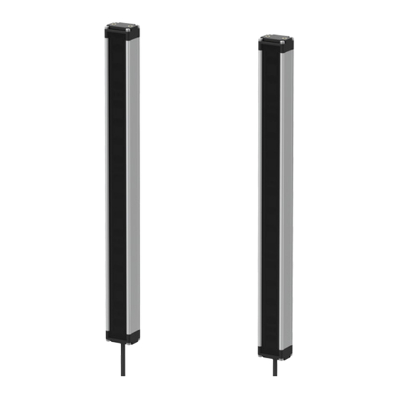
Cross-Beam Area Sensors
BWC Series
PRODUCT MANUAL
For your safety, read and follow the considerations written in the instruction
manual, other manuals and Autonics website.
The specifications, dimensions, etc. are subject to change without notice for product
improvement. Some models may be discontinued without notice.
Features
• 3-point cross-beam type detection minimizes non-detection area
• Long sensing distance up to 7 m
• 14 configurations (number of optics: 4 to 20 / optical pitch: 40, 80 mm / detection
area: 120 to 1,040 mm)
• Easy installation with installation mode function
• Mutual interference prevention function, self-diagnosis function
• Self-diagnosis output: sensing screen pollution and blocking of optical axis can be
checked from external device (patent)
• Bright LED indicators on emitter and receiver
• Korean Railway Standard compliant (BWC80-14HD models)
• IP67 protection structure (IEC standard) (patent)
ᜢ ᜣ ᜫ
Safety Considerations
• Observe all 'Safety Considerations' for safe and proper operation to avoid hazards.
• symbol indicates caution due to special circumstances in which hazards may occur.
Warning
Failure to follow instructions may result in serious injury or death.
01. Fail-safe device must be installed when using the unit with machinery that
may cause serious injury or substantial economic loss. (e.g. nuclear power
control, medical equipment, ships, vehicles, railways, aircraft, combustion
apparatus, safety equipment, crime/disaster prevention devices, etc.)
Failure to follow this instruction may result in personal injury, economic loss or
fire.
02. Do not use the unit in the place where flammable/explosive/corrosive gas,
high humidity, direct sunlight, radiant heat, vibration, impact, or salinity
may be present.
Failure to follow this instruction may result in explosion or fire.
03. Do not connect, repair, or inspect the unit while connected to a power
source.
Failure to follow this instruction may result in fire.
04. Check 'Connections' before wiring.
Failure to follow this instruction may result in fire.
05. Do not disassemble or modify the unit.
Failure to follow this instruction may result in fire.
06. This product is not safety sensor and does not observe any domestic nor
international safety standard.
Do not use this product with the purpose of injury prevention or life protection, as
well as in the place where economic loss maybe present.
Caution
Failure to follow instructions may result in injury or product damage.
01. Use the unit within the rated specifications.
Failure to follow this instruction may result in fire or product damage.
02. Use a dry cloth to clean the unit, and do not use water or organic solvent.
Failure to follow this instruction may result in fire.
03. Do not use a load over the range of rated relay specification.
Failure to follow this instruction may result in fire, relay broken, contact melt,
insulation failure or contact failure.
Cautions during Use
• Follow instructions in 'Cautions during Use'. Otherwise, It may cause unexpected
accidents.
• 12 - 24 VDCᜡ power supply should be insulated and limited voltage/current or Class
2, SELV power supply device.
• Use the product, 1 sec after supplying power. When using separate power supply for
the sensor and load, supply power to sensor first.
• When using switching mode power supply to supply the power, ground F.G. terminal
and connect a condenser between 0 V and F.G. terminal to remove noise.
• When connecting a DC relay or other inductive load, remove surge by using diodes
or varistors.
• Wire as short as possible and keep away from high voltage lines or power lines, to
prevent surge and inductive noise.
• This unit may be used in the following environments.
- Indoors (in the environment condition rated in 'Specifications')
- Altitude max. 2,000 m
- Pollution degree 2
- Installation category II
Advertisement

Related Manuals for Autonics BWC Series


Summary of Contents for Autonics BWC Series
- Page 1 For your safety, read and follow the considerations written in the instruction and connect a condenser between 0 V and F.G. terminal to remove noise. manual, other manuals and Autonics website. • When connecting a DC relay or other inductive load, remove surge by using diodes The specifications, dimensions, etc.
- Page 2 -|Transparent Guide|- Cautions during Installation Dimensions • Be sure to install this product by following the usage environment, location, and • Unit: mm, For the detailed drawings, follow the Autonics website. specified ratings. Consider the listed conditions below. Emitter 30.6 Receiver 30.6...
- Page 3 -|Transparent Guide|- Specifications Function ■ Interference Protection (transmitted light frequency change) Model BWC40-□□H BWC40-□□HD BWC80-14H BWC80-14HD Sensing method Through-beam When you install more than two products, there is a risk of mutual interference. Beam pattern 3-point cross beam netting type Change the frequency to prevent this interference.
- Page 4 (sensing distance) (installation allowable distance) 1 ~ 3 m ≥ 0.4 m L (m) ≥ 3 m L × tan 8 ° = ≥ L × 0.14 18, Bansong-ro 513Beon-gil, Haeundae-gu, Busan, Republic of Korea, 48002 www.autonics.com | +82-2-2048-1577 | sales@autonics.com...
Need help?
Do you have a question about the BWC Series and is the answer not in the manual?
Questions and answers