Advertisement
TCD220051AC
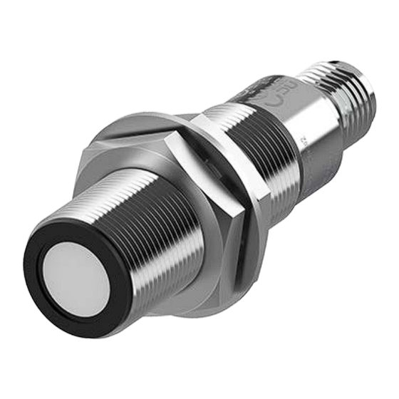
Cylindrical
Ultrasonic Sensors
UTR Series
PRODUCT MANUAL
For your safety, read and follow the considerations written in the instruction
manual, other manuals and Autonics website.
The specifications, dimensions, etc. are subject to change without notice for product
improvement. Some models may be discontinued without notice.
Features
• Detect and measure various material and surface types with ultrasonic sensing
• Sensing distance (by mount diameter)
- Ø 18 mm : 120 to 1,300 mm
- Ø 30 mm : 600 to 8,000 mm
• Temperature compensation (auto/manual) and detection width conversion function
for high accuracy
• 316L stainless steel body for high corrosion resistance
• 360º ring type indicator to check operation status from any directions
• Digital output (Push-Pull) support
• IO-Link models available
• Simultaneous digital and analog output models available
• Configure settings and monitor status with ultrasonic sensor programming units
(UT-P)
• Dedicated software provided (atDistance)
• IP67 protection rating
ᜢ ᜨ ᜬ
Safety Considerations
• Observe all 'Safety Considerations' for safe and proper operation to avoid hazards.
• symbol indicates caution due to special circumstances in which hazards may occur.
Warning
Failure to follow instructions may result in serious injury or death.
01. Fail-safe device must be installed when using the unit with machinery that
may cause serious injury or substantial economic loss. (e.g. nuclear power
control, medical equipment, ships, vehicles, railways, aircraft, combustion
apparatus, safety equipment, crime/disaster prevention devices, etc.)
Failure to follow this instruction may result in personal injury, economic loss or
fire.
02. Do not use the unit in the place where flammable/explosive/corrosive gas,
high humidity, direct sunlight, radiant heat, vibration, impact, salinity,
moisture, or steam, or dust may be present.
Failure to follow this instruction may result in explosion or fire.
03. Do not disassemble or modify the unit.
Failure to follow this instruction may result in fire.
04. Do not connect, repair, inspect, or replace the unit while connected to a
power source.
Failure to follow this instruction may result in fire.
05. Check 'Connections' before wiring.
Failure to follow this instruction may result in fire.
06. Qualified personnel shall carry out installation, configuration.
Responsible person for use is an operator who:
- is fully knowledgeable about the installation, settings, use and
maintenance of the product.
Failure to follow this instruction may cause malfunction or result in accident.
Caution
Failure to follow instructions may result in injury or product damage.
01. Use the product within the rated specifications.
Failure to follow this instruction may result in fire or product damage.
02. Depending on the medium and the ambient temperature, the sound speed
may change and the sensing performance may change.
Use the product within the rated specifications.
03. When the ambient temperature is 70 ℃, make sure that the relative
humidity does not exceed 50 % RH.
Sensing performance may deteriorate in humid environments.
04. Use a dry cloth to clean the unit, and do not use water or organic solvent.
Failure to follow this instruction may result in fire.
05. Do not allow dust to be on the surface of the sensing surface or build up a
thick layer of dust.
Failure to follow this instruction may result in product damage and malfunction.
06. Keep the product away from metal chip, dust, and wire residue which might
flow into the unit.
Failure to follow this instruction may result in fire or product damage.
07. Do not connect the load if power is supplied only to UT-P (sold separately,
ultrasonic sensor programming unit).
Failure to follow this instruction may result in fire or product damage.
08. In case of IO-Link models, IO-Link and UT-P communications cannot be used
simultaneously.
Do not connect wiring arbitrarily.
Product Components
• Product × 1
• Instruction Manual × 1
Sold Separately
• Ultrasonic sensor programming unit
: UT-P Series
• Nut × 2
• Washer × 1
• M12 connector cable: CID5-□, C1D5-□
Advertisement
Table of Contents

Related Manuals for Autonics UTR Series


Summary of Contents for Autonics UTR Series
- Page 1 Do not connect wiring arbitrarily. For your safety, read and follow the considerations written in the instruction manual, other manuals and Autonics website. Product Components The specifications, dimensions, etc. are subject to change without notice for product improvement. Some models may be discontinued without notice.
- Page 2 Software • Follow instructions in ‘Cautions during Use’. Otherwise, it may cause unexpected accidents. Download the installation file and the manuals from the Autonics Website. ■ atDistance • The 12 - 30 VDCᜡpower input is insulated and limited voltage/current or use SELV, Class 2 power supply.
-
Page 3: Specification
-|Transparent Guide|- Wire Setting Unit Descriptions • Depending on wire setting it is available to operate same with the input keys. • It is for the display part supporting models. The settings for supplying power and quick mode are available. •... -
Page 4: Direct Setting
-|Transparent Guide|- Direct Setting Add-On • Some parameters are activated / deactivated depending on the model or setting of • Some parameters are activated / deactivated depending on the model or setting of other parameters. other parameters. • [T1] + [T2] keys: Select the parameter. •... - Page 5 -|Transparent Guide|- Quick Digital Output: Operation Mode ■ Area • The setting method depends on the output method. With the setting in order, the setting value is saved and returned to RUN mode. Determine a switching point1 (SP1) to set the detection area. •...
- Page 6 -|Transparent Guide|- Timer ■ One-point Determine automatically the near and far switching points depending on the • Setting range: 1 to 25 sec, set at 1 sec intervals switching point1 (SP1) and the offset ratio to set the detection area. •...
-
Page 7: Term Definition
-|Transparent Guide|- Temperature Compensation (Auto / Manual) Term Definition • Select Auto or Manual temperature compensation depending on models and environment to minimize the error between the actual distance and the measured value for measurement accuracy. • If the difference between the standard or the actual distance and the measured ①... -
Page 8: Parameter Index
-|Transparent Guide|- Parameter Index ■ Process data • The current data value is displayed in real time. Parameter Bit 7 Bit 6 Bit5 Bit4 Bit3 Bit2 Bit1 Bit0 Byte0 (PD0) Distance Data Distance Data Byte1 (PD1) Byte2 (PD2) Scale Byte3 (PD3) Analog Status Flag Digital Status Flag Parameter Description... - Page 9 -|Transparent Guide|- ■ Parameter menu • Product setting can be changed according to the user environment. Index Setting range Factory default Subindex Parameter Description Type Access hex. dec. UTRCM18 UTRCM30 UTRCM18 UTRCM30 SP1 Teaching SP1 teaching start 0x41 System 0x02 SP2 Teaching SP2 teaching start 0x42...
- Page 10 Segment Table The segments displayed on the product indicate the following meanings. It may differ depending on the product. 7 segment 11 segment 12 segment 16 segment 18, Bansong-ro 513Beon-gil, Haeundae-gu, Busan, Republic of Korea, 48002 www.autonics.com | +82-2-2048-1577 | sales@autonics.com...
Need help?
Do you have a question about the UTR Series and is the answer not in the manual?
Questions and answers