
Related Manuals for FujiFilm FUJINON HZK24-300mm


Summary of Contents for FujiFilm FUJINON HZK24-300mm
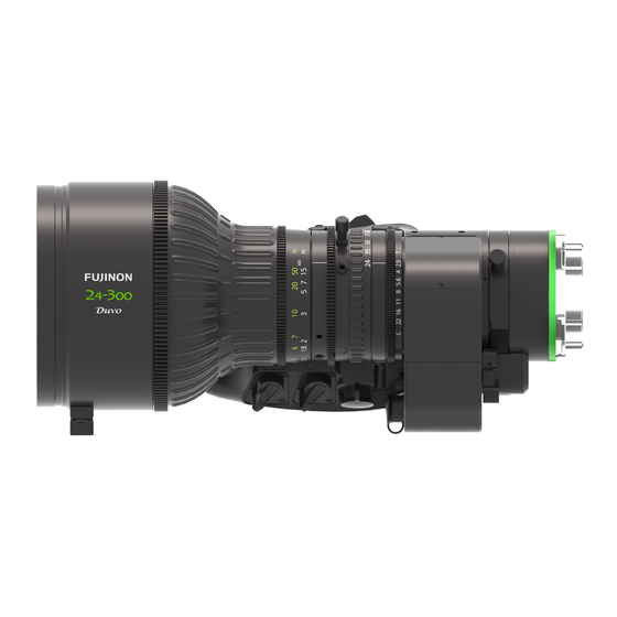
- Page 1 FUJINON LENS 富士能镜头 HZK24 - 300mm HZK14 - 100mm 取扱説明書 Operation Manual 使用手册 BB00058108-301 LP780A-S11 / LP781A-S11 0605...
- Page 2 ご使用になる前に、この取扱説明書をよくお読みください。また、いつでも取り出 してお読みいただけるよう、大切に保管してください。 Before using this product, please read this operation manual carefully, and keep the manual handy for future use. 在使用本产品前, 请先详细阅读本产品使用说明书及妥善保管本使用说明书 作为参考资料。 製品の仕様および外観は、改良のため予告なく変更することがあります。 Design and specifications are subject to change without notice. 产品规格及设计可能在未经通告情况下变更。...
- Page 3 日 本 語 版 ◆ この取扱説明書は 「 日本語版 」 「 英語版 」 「 中文版 」 「 技術資料 」 から構成されて います。 日本語版 英語版 中国語版 技術資料...
- Page 4 MEMO...
- Page 5 安全にお使いいただくために ここでは、製品を安全に正しくご使用いただくために、重要な注意事項を説明しています。 必ずご使用前に読み、 記載内容に従って正しくご使用ください。 文章中の 警告や 注意は次のことを表しています。 警告 誤った取り扱いをしたときに、人が死亡または重傷を負う可能性が想定される 内容を示します。 注意 誤った取り扱いをしたときに、人が傷害を負ったり、物的損害の発生が想定され る内容を示します。 警告 ◆ 本製品の内部に水が入らないようにしてください。 火災や感電の原因となります。 万一水が入ったときは、すぐに本製品に供給している電源を切ってください。 ◆ 取り付け ・ 締め付けは確実に行ってください。 高所使用時の落下は重大な事故の原因となります。 ◆ 太陽や高輝度の光源を、レンズを通してみないでください。 目に障害を負うおそれがあります。 注意 ◆ 運搬中の落下は、けがの原因となります。 落とさないように注意してください。 ◆ ご使用になる カメラが、レンズシステム ( レンズとそれに接続される アクセサリ ) の駆動に必要な消費電力を供給 することが可能か、ご使用の前に確認してください。 レンズシステムに必要な電力を供給できない カメラを使用 した場合、レンズの動作不良または...
- Page 6 一般的な注意 ◆ レンズおよびその付属品は精密機械です。 決して強い衝撃を与えないでください。 レンズマウントの フランジ面より後方に レンズ部分が突き出ている レンズの場合、取り付け ・ 取り外しの際、レン ズ部分に衝撃を与えないよう十分に注意してください。 ◆ レンズを寒いところから急に、気温と湿気が高いところに持ち込むと、レンズが曇ることがあります。 上記のような環境へ レンズを持ち込むときは、前もって レンズを使用環境温度へ適合させるなどの曇り対策を講 じてください。 ◆ カメラを操作するときは、レンズの前部に衝撃を与えないよう十分に注意してください。 ◆ カメラを使用しないときは、レンズには レンズキャップを取り付けてください。 ◆ 駆動伝達部がある付属品を取り付ける場合、かみ合い部分の形状に異常はないか、異物の付着はないか十分 に点検してください。 異物があるときは確実に取り除いてください。 形状に異常があるときは 、 購入先販売店に ご相談ください。 ◆ 濃霧 ・ 降雨 ・ 降雪などの環境で使用するときは、 覆いをするなどの対策をして、 製品に水分がかからないよう にしてください。 ◆ 輸送時の レンズへの衝撃を最小限にするために、レンズを カメラから取り外す前に ズームは ワイド端に、フォー カスは無限遠側一杯の位置になるように設定してください。...
-
Page 7: Table Of Contents
目 次 安全にお使いいただくために ・・・・・・・・・・・・・・・・・・・・・・・・・・・・・・・・・・・・・・・・・・・・・・・・・・・・・・・・・・・・・・・・・・・・・・・・・・・・・・ 目 次 ・・・・・・・・・・・・・・・・・・・・・・・・・・・・・・・・・・・・・・・・・・・・・・・・・・・・・・・・・・・・・・・・・・・・・・・・・・・・・・・・・・・・・・・・・・・・・・・・・・・・ レンズの概要 ・・・・・・・・・・・・・・・・・・・・・・・・・・・・・・・・・・・・・・・・・・・・・・・・・・・・・・・・・・・・・・・・・・・・・・・・・・・・・・・・・・・・・・・・・・・・ 商品構成 ・・・・・・・・・・・・・・・・・・・・・・・・・・・・・・・・・・・・・・・・・・・・・・・・・・・・・・・・・・・・・・・・・・・・・・・・・・・・・・・・・・・・・・・・・・・・・・・・ カメラへの取り付け ・・・・・・・・・・・・・・・・・・・・・・・・・・・・・・・・・・・・・・・・・・・・・・・・・・・・・・・・・・・・・・・・・・・・・・・・・・・・・・・・・・・・ フランジバックの調整 ・・・・・・・・・・・・・・・・・・・・・・・・・・・・・・・・・・・・・・・・・・・・・・・・・・・・・・・・・・・・・・・・・・・・・・・・・・・・・・・・・ アイリス操作 ・・・・・・・・・・・・・・・・・・・・・・・・・・・・・・・・・・・・・・・・・・・・・・・・・・・・・・・・・・・・・・・・・・・・・・・・・・・・・・・・・・・・・・・・・・・・ フォーカス操作 ・・・・・・・・・・・・・・・・・・・・・・・・・・・・・・・・・・・・・・・・・・・・・・・・・・・・・・・・・・・・・・・・・・・・・・・・・・・・・・・・・・・・・・・・・ ズーム操作 ・・・・・・・・・・・・・・・・・・・・・・・・・・・・・・・・・・・・・・・・・・・・・・・・・・・・・・・・・・・・・・・・・・・・・・・・・・・・・・・・・・・・・・・・・・・・・・・ マニュアル操作 ・・・・・・・・・・・・・・・・・・・・・・・・・・・・・・・・・・・・・・・・・・・・・・・・・・・・・・・・・・・・・・・・・・・・・・・・・・・・・・・・・・・・・・・・・・・ ズームシーソーコントロールレバーによる操作 ・・・・・・・・・・・・・・・・・・・・・・・・・・・・・・・・・・・・・・・・・・・・・・・・・・・・・・・・・・・・・ クイックズーム操作 ・・・・・・・・・・・・・・・・・・・・・・・・・・・・・・・・・・・・・・・・・・・・・・・・・・・・・・・・・・・・・・・・・・・・・・・・・・・・・・・・・・・・・・・ オートクルージングズーム操作 ・・・・・・・・・・・・・・・・・・・・・・・・・・・・・・・・・・・・・・・・・・・・・・・・・・・・・・・・・・・・・・・・・・・・・・・・・・・ ズームリミット操作 ・・・・・・・・・・・・・・・・・・・・・・・・・・・・・・・・・・・・・・・・・・・・・・・・・・・・・・・・・・・・・・・・・・・・・・・・・・・・・・・・・・・・・・・・ マクロ操作 ・・・・・・・・・・・・・・・・・・・・・・・・・・・・・・・・・・・・・・・・・・・・・・・・・・・・・・・・・・・・・・・・・・・・・・・・・・・・・・・・・・・・・・・・・・・・・・・ その他の機能 ・・・・・・・・・・・・・・・・・・・・・・・・・・・・・・・・・・・・・・・・・・・・・・・・・・・・・・・・・・・・・・・・・・・・・・・・・・・・・・・・・・・・・・・・・・ 機能&モード切替スイッチについて ・・・・・・・・・・・・・・・・・・・・・・・・・・・・・・・・・・・・・・・・・・・・・・・・・・・・・・・・・・・・・・・ アイリスの調整 ・・・・・・・・・・・・・・・・・・・・・・・・・・・・・・・・・・・・・・・・・・・・・・・・・・・・・・・・・・・・・・・・・・・・・・・・・・・・・・・・・・・・・・・・・ レンズフードの着脱 ・・・・・・・・・・・・・・・・・・・・・・・・・・・・・・・・・・・・・・・・・・・・・・・・・・・・・・・・・・・・・・・・・・・・・・・・・・・・・・・・・・・・ 保守... -
Page 8: 商品構成
レンズの概要 フジノンレンズ HZK24-300mm / HZK14-100mm は、スーパー 35mm センサー ( 対角φ 28.55mm ) と 35mm フルサ イズ相当 センサー ( 対角φ 41.3mm ) を搭載した カラーカメラ用に開発された、PL マウントタイプの ズームレンズです。 商品構成 個数 ① レンズ本体 ・・・・・・・・・・・・・・・・・・・・・・・・・・・・・・・・・・・・・・・・・・・・・・・・・・・・・・・・・・・・・・・・・・・・・・・・1 ② 前レンズキャップ ・・・・・・・・・・・・・・・・・・・・・・・・・・・・・・・・・・・・・・・・・・・・・・・・・・・・・・・・・・・・・・・・・・・・・・・・1 ③ 後レンズキャップ *1 ・・・・・・・・・・・・・・・・・・・・・・・・・・・・・・・・・・・・・・・・・・・・・・・・・・・・・・・・・・・・・・・・・・・・・・・・1 ④ フード *1 ・・・・・・・・・・・・・・・・・・・・・・・・・・・・・・・・・・・・・・・・・・・・・・・・・・・・・・・・・・・・・・・・・・・・・・・・1 ⑤ フードキャップ *1 ・・・・・・・・・・・・・・・・・・・・・・・・・・・・・・・・・・・・・・・・・・・・・・・・・・・・・・・・・・・・・・・・・・・・・・・・1 ⑥... -
Page 9: カメラへの取り付け
カメラへの取り付け 注意 レンズおよびカメラのマウントを保護するために、 ブリッジプレートとレンズサポートを使ってレンズを支えてください。 警告 取り付け ・ 締め付けは確実に行ってください。 高所使用時の落下は重大な事故の原因となります。 レンズのマウント面 カメラのマウント面 切り欠き (4 か所 ) ピン ( カメラによって 位置が異なります ) レンズ カメラ 支持枠 ブリッジプレート サポートロッド レンズサポート 三脚 マウントクランプリング ◎ 取り付けは次の手順で行います。 a. ブリッジプレートに カメラと レンズサポートを取り付けます。( 取付方法は ブリッジプレートにより異なります。) b. カメラの マウントクランプリングを反時計方向一杯に回して緩めます。 c. レンズを手で支えながら、 レンズと カメラの マウント面を合わせます。 ( カメラの マウント面にある ピンが、 レンズの マウント面にある切り欠きに確実に入るように位置を合わせてください。... - Page 10 注 . レンズを最初に カメラに取り付けたとき 、 または異なる カメラに取り付けたときには 、 必ず フランジバックの調整 ( 5 ページ参照 ) を行ってください。 注 . ブリッジプレートおよび レンズサポートの取り付け方法については、それぞれの取扱説明書をご参照ください。 △ 注意 レンズサポートの取り付け位置と高さは慎重に調整してください。 レンズとカメラの取け部分に無理な力 がかかると、 レンズまたはカメラのマウントを破損する恐れがあります。 * 支持枠について ・ レンズを サポートロッドに固定するときに使用します。 ・ カメラと ブリッジプレートを取り付けた際に、レンズサポートと支持枠の高さが適合しないときは、支持枠に サポー トフットを取り付けて調節してください。 注 . レンズサポートと支持枠は、必ず固定してお使いください。 レンズが固定されない状態で使用すると、レンズお よび カメラの マウント部を破損する恐れがあります。 サポートフットの取り付け...
-
Page 11: フランジバックの調整
フランジバックの調整 フランジバックとは 、 レンズの取付基準面 ( フランジ ) から結像面までの距離をいいます。 レンズの結像面と カメラの撮像面が一致していないと 、 ズームの操作中に被写体の焦点がずれてしまいます。 これを防ぐために 、 フランジバックの調整が必要となります。 レンズを最初に カメラに取り付けたとき 、 または異なる カメ ラに取り付けたときには 、 必ずこの調整を行ってください。 5.1 被写体および絞りの条件 取付基準面 : 巻末に掲載してあります、白黒 被写体 の放射縞模様 チャート “ ジー 結像面 メンススター” を、活用してくだ さい。 : 約 3 m 被写体距離... - Page 12 5.3 電源を供給できないときの調整 やむを得ず カメラの レンズ用 コネクタから レンズへ電源が供給できない場合、フランジバック調整歯車 ( F.f 調 整歯車 , カバーの内側 ) を、先の細い工具等で回転させて調整を行ってください。 調整は、上記 [c.] の操作を フランジバック調整歯車の回転操作におきかえ、 [b. ~ g.] の手順で行ってください。 調整後、カバーを確実に 取り付けてください。 ゴムキャップ F.f 調整歯車 MEMO - 6 -...
-
Page 13: アイリス操作
アイリス操作 アイリスモード切替スイッチ アイリスモーメンタリスイッチ アイリスリング アイリスの操作方式には、オートアイリスモードと マニュアルモードがあります。 各方式の操作方法については、それ ぞれの項目を参照してください。 ■ オートアイリスモード アイリスモード切替 スイッチを 『 A 』 に設定します。 アイリスは、カメラからの信号により、被写体の明るさに応じ て自動的に調整されます。 注 1 . アイリス A-M ON/OFF スイッチ ( 17 ページ参照 ) を OFF にすると、アイリスモード切替 スイッチの設定に かかわらず、アイリスは マニュアルモードで動作します。 ■ マニュアルモード a. アイリスモード切替 スイッチを 『 M 』 に設定します。 b. -
Page 14: フォーカス操作
フォーカス操作 フォーカスリング フォーカスコントロール用コネクタ フォーカスサーボ / マニュアル切替つまみ 7.1 マニュアル操作 a. フォーカスサーボ/マニュアル切替つまみを 『 M 』 に設定します。 b. フォーカスリングを直接手で回して、焦点を合わせます。 カメラ側より見て時計方向に回すと焦点は至近側 に合い、反時計方向に回すと無限遠側に合います。 7.2 サーボ操作 別売りの サーボ操作用 アクセサリ(フォーカスデマンドコントローラ )を使用すると、遠隔操作を行うこともできます。 サーボ操作用の アクセサリを使用するときは、フォーカスサーボ/マニュアル切替つまみを 『 S 』 に設定してく ださい。 注 1 . フォーカスサーボ/マニュアル切替つまみを 『 S 』 に設定した状態で、 フォーカスリングまたは フォーカ スグリップを無理に操作しないでください。... -
Page 15: ズーム操作
ズーム操作 ズームシーソーコントロールレバー ズームレバー ズームコントロール用コネクタ ズームサーボ / マニュアル切替つまみ ズームリング ズーム操作は、次の 5 通りの方式で行うことができます。 ページ マニュアル操作 ・・・・・・・・・・・・・・・・・・・・・・・・・・・・・・・・・・・・・・・・・・・・・・・・・・・・・・・・・・・・・・ 9 ズームシーソーコントロールレバーによる操作 ・・・・・・・・・・・・・・・・・・・・・・・・・・・・・・・・・・・・・ 10 クイックズーム操作 ・・・・・・・・・・・・・・・・・・・・・・・・・・・・・・・・・・・・・・・・・・・・・・・・・・・・・・・・・・・ 10 オートクルージングズーム操作 ・・・・・・・・・・・・・・・・・・・・・・・・・・・・・・・・・・・・・・・・・・・・・・・・・ 11 ズームリミット操作 ・・・・・・・・・・・・・・・・・・・・・・・・・・・・・・・・・・・・・・・・・・・・・・・・・・・・・・・・・・・・ 12 各方式での操作方法については、それぞれの項目を参照してください。 なお、別売りの アクセサリを使用すると、 遠隔操作を行うこともできます。 注 . 外付け モータを取り付けて操作する場合は、 ズームサーボ/マニュアル切替つまみを マニュアルに設定 してください。 故障の原因になります。 8.1 マニュアル操作 a. -
Page 16: ズームシーソーコントロールレバーによる操作
8.2 ズームシーソーコントロールレバーによる操作 a. ズームサーボ/マニュアル切替つまみを 『 S 』 に設定します。 b. ズームシーソーコントロールレバーを押します。 レバーの T 側を押すと ズームは テレ側に、 W 側を押すと ワイド側に作動します。 レバーを押す深さを変えると ズームスピードが変化します。 深く押すと速くなり、浅く押すと遅くなります。 〈 ズーム最大 スピードの調節 〉 ズーム最大 スピード調節つまみ ( 下図参照 ) を操作すると、ズームの最大 スピードを 7 段階の間で、任意に調 節することができます。 つまみを時計方向に回すと、スピードは速くなります。 ズーム最大スピード調節つまみ クイックズーム&オートクルージング ズームスイッチ 8.3 クイックズーム操作 クイックズーム操作では、ズームを素早く... -
Page 17: オートクルージングズーム操作
8.4 オートクルージングズーム操作 ズームを一定の スピードで、テレ端または ワイド端まで作動させる操作です。 この機能は、低速で ズーミングスピードを維持したいときに有効に活用することができます。 注 . ズームリミット機能を使用しているときは、ズームリミット位置で ズームは停止します。 このため、テレ端また は ワイド端まで作動しない場合があります。 8.4.1 操作方法 a. ズームサーボ/マニュアル切替つまみを 『 S 』 に設定します。 b. ズームシーソーコントロールレバーを押して ズームスピードを調節します。 c. ズームシーソーコントロールレバーを押したまま クイックズーム& オートクルージングズームスイッチを押しま す。 ─ オートクルージングズーム機能が働きます。 d. ズームシーソーコントロールレバーから手を離します。 ─ ズームは、クイックズーム& オートクルージングズームスイッチを押した時点での スピードのまま、テレ端 または ワイド端まで作動し続けます。 8.4.2 解除方法... -
Page 18: ズームリミット操作
8.5 ズームリミット操作 ズームリミット機能は サーボ操作時に使用することができます。 ( ズームリミット位置の設定は、 マニュアル操作で行います。) この機能を使用しますと、 テレ側および ワイド側への ズームの動きをそれぞれ制限して、必要な範囲内だけの ズーム操作を行うことができます。 ズームリミット ON/OFF 切替スイッチ (SW1- ⑧ ) スイッチ 詳細図 LED ( カバーの内側 ) ズームシーソーコントロールレバー MEMO - 12 -... - Page 19 8.5.1 ズームリミット位置の設定 ・ 工場出荷時、 ズームリミット位置は テレ端および ワイド端に設定してあります。 a. ズームリミットON/OFF切替 スイッチ ( 機能& モー ド切替 スイッチの SW1- ⑧ ) が 『 OFF 』 に設定さ れている場合、『 ON 』 に切り替えます。 テレ端 ワイド端 b. ズームサーボ / マニュアル切替つまみを 『 M 』 に ズーム作動範囲 設定します。 c. マニュアル操作で ズームを動かし、テレ側の リ ミット位置として設定したい場所で停止させます。...
- Page 20 8.5.2 ズームリミットの操作 a. ズームサーボ/マニュアル切替つまみが 『 M 』 に設定されている場合、『 S 』 に切り替えます。 b. ズームリミット ON/OFF 切替 スイッチが 『 OFF 』 に設定されている場合、『 ON 』 に切り替えます。 c. ズームシーソーコントロールレバーを操作して ズームを作動させます。 レバーの 『 T 』 側を押し続けると ズームは、テレ側の ズームリミット位置まで動いて停止します。 レバーの 『 W 』 側を押し続けると ズームは、ワイド側の ズームリミット位置まで動いて停止します。 注...
-
Page 21: マクロ操作
マクロ操作 マクロリング マクロレバー マクロ操作 ( 近接撮影 ) は、次のようにして行います。 9.1 マクロ操作 a. フォーカスリングを至近側一杯に回します。 b. マクロレバーを引きながら、マクロリングを カメラ側から見て時計方向一杯に回します。 c. ズームを操作して焦点を合わせます。 注 1 . マクロ操作をする前に、ズームリミット ON/OFF スイッチを OFF にしてください。( 18 ページ参照 ) 注 2 . マクロリングが中間の位置でも、撮影を行うことができます。 この場合、最短撮影距離と撮影範囲は、通常撮影の場合と マクロ撮影の場合の中間の値となります。 9.2 解除方法 マクロリングを カメラ側から見て反時計方向に、マクロレバーが自動的に元の位置に戻るまで回します。 MEMO - 15 -... - Page 22 その他の機能 ■ エクステンダ/エクスパンダ切替 レバー この切替 レバーを回し 『 × 1.5 』 に合わせること により、 内蔵 エクステンダ/エクスパンダが光路 に入ります。 ※ エクスパンダとは イメージサークルを拡張し、 焦 点距離が望遠側に シフトすることで 35mm フル サイズ相当の センサー ( 対角φ 41.3 mm ) にも 対応できる機能です。 ■ VTR スイッチ カメラに接続されている VTR の スタート/ストッ プ操作を行う スイッチです。 スイッチを押すごと VTR スイッチ...
-
Page 23: 機能&モード切替スイッチについて
機能&モード切替スイッチについて この レンズに組み込まれている各種の スイッチは、その スイッチに設定されている機能を切り替えて使用することがで きます。 機能を切り替えるには、駆動 ユニット前面の 「 機能& モード切替 スイッチ 」 の設定を変更します。 駆動 ユニット前面 の長円形の ゴムキャップを外すと、「 機能& モード切替 スイッチ 」 を操作することができます。 機能&モード切替スイッチ ゴムキャップ ① ② ③ ④ ⑤ ⑥ ⑦ ⑧ 図は、 工場出荷時の設定位置を示します。 クイックズーム ON / OFF スイッチ オートクルージングズーム... - Page 24 機能&モード切替スイッチ ① ゴムキャップ ② ③ ④ ⑤ ⑥ ⑦ ⑧ 図は、 工場出荷時の設定位置を示します。 クイックズーム ON / OFF スイッチ オートクルージングズーム ON / OFF スイッチ ① ⑤ 画角補正 (BCT) 機能 ON / OFF スイッチ アイリス補正 ON / OFF スイッチ ② ⑥ アイリス A-M 位置切替スイッチ ③...
- Page 25 機能&モード切替スイッチ ゴムキャップ ① ② ③ ④ ⑤ 図は、 工場出荷時の設定位置を示します。 カメラ通信 ON / OFF スイッチ ① フォーカスモード ON / OFF スイッチ ② 予備スイッチ ④ アナログズームデマンド ③ ⑤ ズームモード切替スイッチ ズームモード機能 ON / OFF スイッチ ① カメラ通信 ON / OFF スイッチ カメラとの シリアル通信を、有効 ( ON ) または無効 ( OFF ) に切り替える スイッチです 。 注.
- Page 26 ■ スイッチ機能一覧表 クイックズーム& オートクルージングズームスイッチおよび アイリスモード切替 スイッチは、 機能& モ ード切替 ス イッチの設定の組み合わせによって機能が異なります。 次の表を参照してください。 ◎ クイックズーム& オートクルージングズームスイッチ 機能& モード 切替 スイッチの設定 SW1- ① SW1- ⑤ クイックズーム& オートクルージングズームスイッチの機能 オートクルージング クイックズーム ON ズーム機能 ON クイックズーム& オートクルージングズーム スイッチ スイッチは機能しません クイックズーム スイッチ オートクルージングズーム スイッチ ◎ アイリスモード切替 スイッチ 機能& モード 切替 スイッチの設定 SW1- ⑦...
- Page 27 アイリスの調整 工場出荷時には、アイリスは標準状態 ( 図示された初期位置 ) に設定されています。 通常は初期状態のままで使用 できますが、 何らかの理由で調整が必要になったときには、下記の要領で調整を行うことができます。 ・ 調整用 トリマは、駆動 ユニットの内部にあります。 駆動 ユニット前面の キャップを外すと調整用 トリマが見えますので、小型 ドライバ等を使用して トリマを回してください。 ゴムキャップ アイリス感度調整トリマ 図は、工場出荷時の設定位置を示します。 ■ アイリス感度調整 アイリス感度調整 トリマを時計方向に回すと アイリスの感度が上がり、 反時計方向に回すと下がります。 なお、 感 度を上げるときは、ハンチングを起こさないように注意してください。 MEMO - 21 -...
-
Page 28: レンズフードの着脱
レンズフードの着脱 フード取付つまみ 指標点 (レンズフード) 13.1 取り外し a. フード取付つまみを反時計方向に回してゆるめます。 b. レンズフードをまっすぐ前方に引いて外します。 13.2 取り付け a. フード取付つまみを反時計方向に回してゆるめておきます。 b. レンズフードを、 レンズ本体の突き当て面まで差し込みます。 c. フード取付つまみを締め付けて固定します。 MEMO - 22 -... -
Page 29: 保守 ・ 点検
保守 ・ 点検 14.1 レンズの清掃 市販の レンズクリーナおよび レンズクリーニングペーパーを用意します。 a. 初めに、レンズ表面のほこりを、柔らかい刷毛や ブロアーブラシなどで払い落とします。 b. クリーニングペーパーを適当な大きさに折り、一部を レンズクリーナに浸します。 ペーパーの湿った部分で、レンズの中心部から周辺部に向けて渦巻きを描きながら軽く拭きます。 新しい ペーパーを使用して、拭き残りがなくなるまでこの作業を繰り返してください。 14.2 湿気の除去 レンズ本体に水分が付着した場合には、 まず、 速やかに乾いた布で外部の水分を拭き取ってください。 次に、 乾燥剤と共に ビニール袋に入れて密封し、完全に除湿してください。 14.3 保 管 長期間 レンズを使用しないときは、高温、多湿、腐食性 ガスのある場所を避けて保管してください。 14.4 注意事項 本 レンズは、光学 ユニットと駆動 ユニットから構成されています。 両 ユニットは、ねじで止められていますが、こ のねじは外さないでください。 製品の機能を損ねたり、感電の原因となります。 14.5 点... -
Page 30: コネクタの端子配置
コネクタの端子配置 本機の コネクタの端子配置及び 機能は下記の通りです。 カメラ用ケーブル 拡張用コネクタ ズームコントロール用コネクタ フォーカスコントロール用コネクタ ■ フォーカスコントロール用コネクタ ■ ズームコントロール用コネクタ ⑨ ① ⑨ ① ⑧ ⑩ ② ⑧ ⑩ ② HR10G-10R-12S (HIROSE) HR10G-10R-12S (HIROSE) ⑦ ⑫⑪ ③ ⑦ ⑫⑪ ③ ⑥ ⑤ ④ ⑥ ⑤ ④ SIGNAL SIGNAL 1 +V (+12V DC) 1 +V... -
Page 31: オプショナルアクセサリ
オプショナルアクセサリ 16.1 オールサーボシステム- 1 (デジタルフォーカス、 デジタルズーム) アクセサリ名称 型名 備考 EPD-41A-D01 つまみの操作角は 1 回転です。 フォーカス操作用のコ フォーカスポジション ① ントロールユニットで デマンドユニット EPD-41A-D02 つまみの操作角は 2 回転です。 す。 ズームレート ERD-40A-D01 ② ズーム操作、 プリセット操作用のコントロールユニットです。 デマンドユニット MCA-37 ERD、 EPD をパン棒に取り付けるときに使用します。 ③ マウンティングクランプ ④ レンズ オールサーボシステム- 1 システム図 ④... - Page 32 16.2 オールサーボシステム-2 (パーソナルコンピュータによる制御) アクセサリ名称 型名 備考 アイリス、 フォーカス、 ズームをパーソナルコンピュータか SA-206D-005 ① 延長ケーブル ら操作するときに使用します。 ② レンズ ③ パーソナルコンピュータ オールサーボシステム- 2 システム図 ② ① ③ - 26 -...
-
Page 33: 仕 様
仕 様 型名 HZK24-300mm 項目 35mm フルサイズ相当 スーパー 35mm センサ搭載 カメラ 適用 カメラ センサ搭載 カメラ 対角φ 28.55mm 対角φ 41.3mm 画面寸法 24~300mm [ 36~450mm ] *1 < 36~450mm > *2 焦点距離 12.5 倍 ズーム比 エクステンダ 1.5 倍 /エクスパンダ倍率 最大口径時 T 値 T2.9 ( 24~207mm)~ T4.2 ( 300mm ) <T4.35(36~310mm)~T6.3(450mm)>*2 (... - Page 34 型名 HZK14-100mm 項目 35mm フルサイズ相当 スーパー 35mm センサ搭載 カメラ 適用 カメラ センサ搭載 カメラ 対角φ 28.55mm 対角φ 41.3mm 画面寸法 14~100mm [ 21~150mm ] *1 < 21~150mm > *2 焦点距離 7.1 倍 ズーム比 エクステンダ 1.5 倍 /エクスパンダ倍率 最大口径時 T 値 T2.9 ( 14~75mm)~T3.9 ( 100mm ) <T4.35(21~111mm)~T5.85(150mm)>*2 (...
-
Page 35: English Version
ENGLISH VERSION ◆ This operation manual is composed of the Japanese version, English version, and Chinese version. Japanese Version English Chinese Version Version Technical Drawings... - Page 36 For Customers in UK UK Importer : FUJIFILM UK Ltd. Fujifilm House, Whitbread Way, Bedford, Bedfordshire, MK42 0ZE, United Kingdom...
-
Page 37: For Your Safety
FOR YOUR SAFETY This content explains important notices for all the users to use this product safely. Read the content carefully before using, and follow the instructions. The following signs of WARNING and CAUTION show: WARNING Indicates the possibility of causing death or serious injury when misused. CAUTION Indicates the possibility of causing injury or substantial damage when misused. - Page 38 NOTICES ◆ Lens and its accessories are extremely precise instrument, then be sure not to apply the strong impacts to them. If the lens is of a type in which the rear lens protrudes from the flange surface of the lens mount, be sure not to apply impact to the lens part when installing or releasing.
-
Page 39: Contents
CONTENTS FOR YOUR SAFETY ・・・・・・・・・・・・・・・・・・・・・・・・・・・・・・・・・・・・・・・・・・・・・・・・・・・・・・・・・・・・・・・・・・・・・・・・・・・・・・・・・・・・・・ CONTENTS ・・・・・・・・・・・・・・・・・・・・・・・・・・・・・・・・・・・・・・・・・・・・・・・・・・・・・・・・・・・・・・・・・・・・・・・・・・・・・・・・・・・・・・・・・・・ GENERAL DESCRIPTION ・・・・・・・・・・・・・・・・・・・・・・・・・・・・・・・・・・・・・・・・・・・・・・・・・・・・・・・・・・・・・・・・・・・・・・・ LIST OF COMPONENTS ・・・・・・・・・・・・・・・・・・・・・・・・・・・・・・・・・・・・・・・・・・・・・・・・・・・・・・・・・・・・・・・・・・・・・・・・・ INSTALLATION ONTO CAMERA ・・・・・・・・・・・・・・・・・・・・・・・・・・・・・・・・・・・・・・・・・・・・・・・・・・・・・・・・・・・・・・ ADJUSTMENT OF FLANGE FOCAL LENGTH ・・・・・・・・・・・・・・・・・・・・・・・・・・・・・・・・・・・・・・・・・・・ IRIS OPERATION ・・・・・・・・・・・・・・・・・・・・・・・・・・・・・・・・・・・・・・・・・・・・・・・・・・・・・・・・・・・・・・・・・・・・・・・・・・・・・・・・・・・・ FOCUS OPERATION ・・・・・・・・・・・・・・・・・・・・・・・・・・・・・・・・・・・・・・・・・・・・・・・・・・・・・・・・・・・・・・・・・・・・・・・・・・・・・・・ ZOOM OPERATION ・・・・・・・・・・・・・・・・・・・・・・・・・・・・・・・・・・・・・・・・・・・・・・・・・・・・・・・・・・・・・・・・・・・・・・・・・・・・・・・・ Manual Operation ・・・・・・・・・・・・・・・・・・・・・・・・・・・・・・・・・・・・・・・・・・・・・・・・・・・・・・・・・・・・・・・・・・・・・・・・・・・・・・・・・・・・・・ Operation by Zoom Seesaw Control Lever ・・・・・・・・・・・・・・・・・・・・・・・・・・・・・・・・・・・・・・・・・・・・・・・・・・・・・・・・・・... -
Page 40: General Description
2. GENERAL DESCRIPTION The HZK24-300mm / HZK14-100mm Fujinon lens is a PL mount type zoom lens developed for cameras equipped with a Super 35mm sensor (diagonalhφ28.55mm) or 35mm full-size equivalent sensor (diagonal φ41.3mm). 3. LIST OF COMPONENTS QUANTITY ① Lens package ・・・・・・・・・・・・・・・・・・・・・・・・・・・・・・・・・・・・・・・・・・・・・・・・・・・・・・・・・・・・・・・・・・・・・・・・1 ②... -
Page 41: Installation Onto Camera
4. INSTALLATION ONTO CAMERA CAUTION To protect the lens and the camera mount, use the bridge plate and lens support to support the lens. △ WARNING Be sure to attach all the parts securely.Dropping any parts from a height may cause severe accidents. - Page 42 Note : Make sure to adjust the flange focal length when installing the lens on a camera for the first time or installing it on another camera (refer to page 5). Note : For the installation method of the Bridge Plate and Lens Support, refer to the operation manual that came with each product.
-
Page 43: Adjustment Of Flange Focal Length
5. ADJUSTMENT OF FLANGE FOCAL LENGTH The flange focal length is the distance from the flange (mounting surface) of a lens to the focal plane. If the focal plane of the lens does not coincide with the image plane of the camera, the object will be out of focus during a zoom operation. - Page 44 5.3 Adjustment without power If power cannot be supplied from the lens connector on the camera to the lens for some unavoidable rea- son, rotate the F.f adjustment gear (located inside the cover) using a finely pointed tool, for example, and adjust. If this adjustment is to be performed, replace the operation in step [c.] above with the operation in- volved in rotating the gear used for the flange-back adjustment, and proceed by performing steps [b.
-
Page 45: Iris Operation
6. IRIS OPERATION IRIS MODE SELECT SWITCH IRIS MOMENTARY SWITCH IRIS RING There are two iris operation modes: auto iris mode and manual mode. For the operating instruction in each mode, refer to the description on each mode. ■ AUTO IRIS MODE Set the iris mode select switch to “A.”... -
Page 46: Focus Operation
7. FOCUS OPERATION FOCUS RING CONNECTOR FOR FOCUS CONTROL FOCUS SERVO / MANUAL SELECT KNOB 7.1 Manual Control a. Set the focus servo/manual select knob to “M”. b. Focusing can be done by directly rotating the focus ring by hand. Rotate the focus ring clockwise from the camera side to focus on an object on the near side. -
Page 47: Zoom Operation
8. ZOOM OPERATION ZOOM SEESAW CONTROL LEVER ZOOM LEVER CONNECTOR FOR ZOOM ZOOM SERVO/MANUAL SELECT KNOB CONTROL ZOOM RING The zoom can be operated in the following five operation modes. Page 8.1 Manual Operation ・・・・・・・・・・・・・・・・・・・・・・・・・・・・・・・・・・・・・・・・・・・・・・・・・・・・・・・・・・・・・・・・・・・・・・ 9 8.2 Operation by Zoom Seesaw Control Lever ・・・・・・・・・・・・・・・・・・・・・・・・・・・・・・・・・・・・・・・・・・・・・ 10 8.3 QuikZoom Operation ・・・・・・・・・・・・・・・・・・・・・・・・・・・・・・・・・・・・・・・・・・・・・・・・・・・・・・・・・・・・・・・・・・・... -
Page 48: Operation By Zoom Seesaw Control Lever
8.2 Operation by Zoom Seesaw Control Lever a. Set the zoom servo/manual select knob to “S.” b. Press the zoom seesaw control lever. Press T-side of the lever to zoom to the tele side, and the W-side to zoom to the wide side. For the speed control, adjust the strength to press the lever. -
Page 49: Auto Cruising Zoom Operation
8.4 Auto Cruising Zoom Operation In auto cruising zoom operation, the zoom moves to the tele end or the wide end at a constant speed. This function is effective when a constant slow zoom speed is required across the zooming range. Note : If the zoom limit function is used, the zoom will stop at the zoom limit positions.In this case, the zoom may not reach the tele end or the wide end. -
Page 50: Zoom Limit Operation
8.5 Zoom Limit Operation The zoom limit function can be used in the servo operation mode. (The setting of the zoom limit positions can be done in the manual operation mode.) By using this function, the zoom movement toward both the tele side and the wide side can be confined; there- fore, zooming can be done within the desired shot angles. - Page 51 8.5.1 Setting of Zoom Limit Positions ・ Before shipment at the factory, the zoom limit positions were set at the tele end and the wide end respectively. a. If the zoom limit ON/OFF switch (SW1-⑧) is set (Tele End) (Wide End) to “OFF,”...
- Page 52 8.5.2 Zoom Limit Operation a. If the zoom servo/manual select knob is set to “M,” change it to “S.” b. If the zoom limit ON/OFF select switch is set to “OFF,” change it to “ON.” c. By means of the zoom seesaw control lever, operate the zoom. Keep pressing the “T”...
-
Page 53: Macro Operation
9. MACRO OPERATION MACRO RING MACRO LEVER Carry out the following steps for the macro operation (taking a close-up shot). 9.1 Operation a. Turn the focus ring all the way to the minimum object distance side. b. While pulling the macro lever toward the mount, rotate the macro ring toward the arrow as far as it goes. c. -
Page 54: Other Functions
10. OTHER FUNCTIONS ■ Extender / Expander Select Lever To use the built-in extender/expander, rotate the extender/expander select lever to align "×1.5". Note : The expander expands the image circle and shifts the focal length to the tele side, providing compatibility with 35mm full- size equivalent sensors (diagonal φ... -
Page 55: About Function & Mode Select Switches
11. ABOUT FUNCTION & MODE SELECT SWITCHES The function of some switches incorporated in this lens can be changed to other functions. The function can be changed by setting switches in the function & mode select switches. The function & mode select switches are accessible by removing the round rectangular rubber cap on the front of the drive unit. - Page 56 FUNCTION & MODE SELECT SWITCHES ① Rubber cap ② ③ ④ ⑤ ⑥ ⑦ ⑧ The illustration shows the positions set at the factory. AUTO CRUISING ZOOM ON/OFF QUICKZOOM ON/OFF SWITCH ① ⑤ SWITCH BREATHING COMPENSATION IRIS COMP ON/OFF SWITCH ②...
- Page 57 FUNCTION & MODE SELECT SWITCHES Rubber cap ① ② ③ ④ ⑤ CAMERA COMMUNICATION ON/OFF The illustration shows the positions set at the factory. ① SWITCH AUXILIARY SWITCH FOCUS MODE ON/OFF SWITCH ② ④ ANALOG ZOOM DEMAND ZOOM MODE ZOOM MODE SELECT SWITCH ③...
- Page 58 ■ TABLE OF SWITCH FUNCTIONS The functions of switches (quickzoom & auto cruising zoom switch, and iris mode select switch) can be changed to other functions by combination of the settings of the function & mode select switches. Refer to the following tables. ◎...
-
Page 59: Iris Adjustment
12. IRIS ADJUSTMENT Since the iris is precisely adjusted at the factory before shipment, normally the readjustment is not required. However, if readjustment is required for some reason, readjustment can be performed as described below. The adjusting trimmer becomes visible inside the drive unit by removing the cap at the front of the drive unit. Use a small screwdriver or similar implement to rotate the trimmer. -
Page 60: Detaching/Attaching Lens Hood
13.DETACHING/ATTACHING LENS HOOD HOOD ATTACHING KNOB INDEX MARK (LENS HOOD) 13.1 DETACHING a. Rotate the hood attaching knob counterclockwise to loosen it. b. Pull the lens hood straight toward the front to detach it. 13.2 ATTACHING a. Rotate the hood attaching knob counterclockwise to loosen it. b. -
Page 61: Maintenance
14. MAINTENANCE 14.1 CLEANING THE LENS Prepare lens cleaning liquid and lens cleaning paper on the market. a. First use a soft brush or blower brush to brush dust off the surface of the lens. b. Fold the cleaning paper to an adequate size, and dip a part of it into the liquid. Lightly wipe the lens from the center to the periphery while drawing a spiral with the wet paper part. -
Page 62: Pin Assignment Of Connectors
15. PIN ASSIGNMENT OF CONNECTORS The pin assignment and functions of the connectors of this product are as follows. CABLE TO CAMERA CONNECTOR FOR EXPANSION CONNECTOR FOR ZOOM CONTROL CONNECTOR FOR FOCUS CONTROL ■ CONNECTOR FOR ■ CONNECTOR FOR ⑨ ①... -
Page 63: Optional Accessories
16. OPTIONAL ACCESSORIES 16.1 All Servo System ー 1 (Digital Focus,Digital Zoom) ACCESSORY NAME MODEL REMARKS (Operation angle of the knob EPD-41A-D01 is one turn.) Focus Position Control unit for ① Demand Unit focus operation. (Operation angle of the knob EPD-41A-D02 is two turns.) Zoom Rate Demand... - Page 64 16.2 All Servo Systemー2 (Control by Personal Computer) ACCESSORY NAME MODEL REMARKS Required when a personal computer is used to EXTENSION CABLE SA-206D-005 ① control the iris, focus and zoom of the lens. Lens ② Personal Computer ③ Configuration All Servo System ー 2 ②...
-
Page 65: Specifications
17. SPECIFICATIONS MODEL HZK24-300mm TIEM Camera with 35mm Application Camera with super 35mm sensor full-size equivalent sensor Image Format Diagonal φ28.55mm Diagonal φ41.3mm Focal Length 24~300mm [36~450mm]*1 <36~450mm>*2 Zoom Ratio 12.5× Extender / expander 1.5× magnification ratio Maximum Photometric T2.9 ( 24~207mm ) ~ T4.2 ( 300mm ) <T4.35 ( 36~310mm ) ~... - Page 66 MODEL HZK14-100mm TIEM Camera with 35mm Application Camera with super 35mm sensor full-size equivalent sensor Image Format Diagonal φ28.55mm Diagonal φ41.3mm Focal Length 14~100mm [21~150mm]*1 <21~150mm>*2 Zoom Ratio 7.1× Extender / expander 1.5× magnification ratio Maximum Photometric T2.9 ( 14~75mm ) ~ T3.9 ( 100mm ) <T4.35 ( 21~111mm ) ~T5.85 (150mm ) >*2 Aperture ( T No.
- Page 67 中 文 版 ◆ 本使用手册包含日文版本英文版本中文版本。 日文版 英文版 中文版 技术资料...
- Page 68 产品中有害物质的名称及含量 ■ 有害物质 铅 汞 镉 六价铬 多溴联苯 多溴二苯醚 部件名称 Pb ) Hg ) Cd ) Cr ( PBB ) PBDE ) 本体 外壳 ( 金属部件 ) × ○ ○ ○ ○ ○ 外壳 ( 树脂部件 ) ○ ○ ○ ○...
- Page 69 为安全使用本产品 以下是本产品的重要安全使用须知。 请在使用前仔细阅读并遵守指示。 文中的 警告 及 注意 表示 : 警告 使用不当可能导致死亡或严重伤害。 注意 使用不当可能导致人员伤害或物品损坏。 警告 ◆ 产品内部切勿受潮。 这样可能引起火灾或触电。 如果出现异常情况, 立即切断镜头电源。 切勿继续使用。 , 部件的坠落, 可能会导致严重事故。 ◆ 务必将所有部件稳固连接。 在高处使用时 ◆ 切勿通过镜头目视太阳等任何强光源, 以免伤害眼睛。 注意 ◆ 携带镜头时务必小心。 如果镜头脱落, 可能会损坏以及造成人体伤害。 ◆ 必须确认要使用镜头部件 ( 镜头及附件 ) 的摄像机能向镜头部件提供足够的电源。 否则镜头部件将无法正常工作,...
- Page 70 备忘 - ii -...
- Page 71 目 录 为安全使用本产品 ・・・・・・・・・・・・・・・・・・・・・・・・・・・・・・・・・・・・・・・・・・・・・・・・・・・・・・・・・・・・・・・・・・・・・・・・・・・・・・・・・・・・・・・・・ . 目录 ・・・・・・・・・・・・・・・・・・・・・・・・・・・・・・・・・・・・・・・・・・・・・・・・・・・・・・・・・・・・・・・・・・・・・・・・・・・・・・・・・・・・・・・・・・・・・・・・・・・・・・・ . 一般说明 ・・・・・・・・・・・・・・・・・・・・・・・・・・・・・・・・・・・・・・・・・・・・・・・・・・・・・・・・・・・・・・・・・・・・・・・・・・・・・・・・・・・・・・・・・・・・・・・・ . 商品附件 ・・・・・・・・・・・・・・・・・・・・・・・・・・・・・・・・・・・・・・・・・・・・・・・・・・・・・・・・・・・・・・・・・・・・・・・・・・・・・・・・・・・・・・・・・・・・・・・・ . 连接摄像机 ・・・・・・・・・・・・・・・・・・・・・・・・・・・・・・・・・・・・・・・・・・・・・・・・・・・・・・・・・・・・・・・・・・・・・・・・・・・・・・・・・・・・・・・・・・・・・・ . 镜座距的调节 ・・・・・・・・・・・・・・・・・・・・・・・・・・・・・・・・・・・・・・・・・・・・・・・・・・・・・・・・・・・・・・・・・・・・・・・・・・・・・・・・・・・・・・・・・・・ . 光圈操作 ・・・・・・・・・・・・・・・・・・・・・・・・・・・・・・・・・・・・・・・・・・・・・・・・・・・・・・・・・・・・・・・・・・・・・・・・・・・・・・・・・・・・・・・・・・・・・・・・ . 聚焦操作 ・・・・・・・・・・・・・・・・・・・・・・・・・・・・・・・・・・・・・・・・・・・・・・・・・・・・・・・・・・・・・・・・・・・・・・・・・・・・・・・・・・・・・・・・・・・・・・・・ . 变焦操作 ・・・・・・・・・・・・・・・・・・・・・・・・・・・・・・・・・・・・・・・・・・・・・・・・・・・・・・・・・・・・・・・・・・・・・・・・・・・・・・・・・・・・・・・・・・・・・・・・ 1 手动操作 ・・・・・・・・・・・・・・・・・・・・・・・・・・・・・・・・・・・・・・・・・・・・・・・・・・・・・・・・・・・・・・・・・・・・・・・・・・・・・・・・・・・・・・・・・・・・・・・・ 2 圧板式变焦控制杆操作 ・・・・・・・・・・・・・・・・・・・・・・・・・・・・・・・・・・・・・・・・・・・・・・・・・・・・・・・・・・・・・・・・・・・・・・・・・・・・・・・・ 3 快速变焦操作 ・・・・・・・・・・・・・・・・・・・・・・・・・・・・・・・・・・・・・・・・・・・・・・・・・・・・・・・・・・・・・・・・・・・・・・・・・・・・・・・・・・・・・・・・・・ 4 自动导航变焦操作 ・・・・・・・・・・・・・・・・・・・・・・・・・・・・・・・・・・・・・・・・・・・・・・・・・・・・・・・・・・・・・・・・・・・・・・・・・・・・・・・・・・・・・・ 5 变焦限位操作...
- Page 72 . 一般说明 HZK24-300mm / HZK14-100mm 是为配备 Super 35mm 传感器 ( 对角 φ 28.55mm ) 和 35mm 全画 富士能镜头 41.3mm ) 的彩色摄像机开发的 PL 接口型变焦镜头。 幅等效传感器 ( 对角 φ . 商品附件 数量 ① 镜头本体 ・・・・・・・・・・・・・・・・・・・・・・・・・・・・・・・・・・・・・・・・・・・・・・・・・・・・・・・・・・・・・・・・・・・・・・・・・・・・・・ ② 前镜头盖 ・・・・・・・・・・・・・・・・・・・・・・・・・・・・・・・・・・・・・・・・・・・・・・・・・・・・・・・・・・・・・・・・・・・・・・・・・・・・・・ ③ 后镜头盖 ・・・・・・・・・・・・・・・・・・・・・・・・・・・・・・・・・・・・・・・・・・・・・・・・・・・・・・・・・・・・・・・・・・・・・・・・・・・・・・ ④ 遮光罩 ・・・・・・・・・・・・・・・・・・・・・・・・・・・・・・・・・・・・・・・・・・・・・・・・・・・・・・・・・・・・・・・・・・・・・・・・・・・・・・...
- Page 73 . 连接摄像机 , 请使用桥板和镜头支架支撑镜头。 注 意 为了保护镜头和摄像机的接口 , 部件的坠落 , 可能会导致严重事故。 警 告 务必将所有部件稳固连接。 在高处使用时 镜头的接口面 摄像机的接口面 槽口 ( 4 处) 定位销 (位置因摄像机而异) 镜头 摄像机 承托轨 托架 桥板 镜头支架 三脚架 支座夹环 ◎ 安装顺序如下。 a. 将摄像机和镜头支架安装到桥板上。( 安装方法因桥板而异。) b. 将摄像机的连接卡环逆时针旋转到底将其拧松。 c. 在用手支撑镜头的同时, 将镜头和摄像机的安装面对齐。 进行定位, 将摄像机安装面上的定位销可靠地插 入镜头卡口面上的槽口中。...
- Page 74 . 首次在摄像机上安装镜头或在不同的摄像机上安装镜头时, 请务必进行后焦的调节 ( 参阅 5 页 )。 注 . 有关桥板和镜头支架的安装方法, 请参阅相应的使用说明书。 注 注 意 请谨慎调整镜头支架的安装位置和高度。 如果对镜头和摄像机的安装部分施加过大的力, 可能 会损坏镜头或摄像机的卡口。 * 关于托架 ・ 用于将镜头固定到支撑杆上。 ・ 安装摄像机和桥板时, 如果镜头支架和托架的高度不匹配, 请在托架上安装支撑脚并进行调整。 . 请务必固定镜头支架和托架进行使用。 如果在没有固定镜头的状态下使用, 可能会损坏镜头和摄像 注 机的卡口部分。 支撑脚的安装 镜头 托架 支撑脚 承托轨 镜头支架 桥板 - 4 -...
- Page 75 . 镜座距的调节 镜座距指从镜头的镜座 ( 安装表面 ) 到聚集面的距离。 如果镜头的聚集面与摄像机的像平面不一致, 在变焦操作时, 物体会模糊。 为防止发生这种情况, 需要调节镜座距。 首次将镜头安装在摄像机上或将镜头安装在另一台摄像机上时, 必须进行调节。 1 拍摄对象和光圈的条件 安装表面 : 请使用本手册末尾所设的具有黑 拍摄对象 聚集面 白射线网纹的 “西门子星标”。 : 大约 3 米 拍摄距离 : 打开或接近打开 光 圈 . 打开光圈使景深变浅, 可以更好地对准焦 注 点。 为了能正确调节镜座距, 请仔细进行 对焦操作。 镜座距...
- Page 76 3 无法供电时的调节 不得已无法从摄像机上的镜连接器给镜头供电时, 请用尖端较细的工具等转动镜座距调节齿轮 ( 防护罩 内侧 ) 进行调节。 [c.] 的操作, 按照 [b. ~ g.] 的步骤进行操作。 调节时请用镜座距调节齿轮的转动操作取代上述 调节后请将防护罩牢固地安装好。 橡胶盖 镜座距调节齿轮 备忘 - 6 -...
- Page 77 . 光圈操作 光圈模式选择开关 / 自动切换开关 光圈手动 光圈环 光圈模式有两种 : 自动光圈和手动光圈。 在各种模式中的操作说明请参阅各种模式的相关介绍。 ■ 自动光圈模式 A ”。 镜头光圈将根据拍摄目标的亮度自动调节。 将光圈模式选择开关设为 “ . 如果将光圈 A-M ( 自动光圈 ) ON/OFF 开关 ( 参见 17 页 ) 设为 OFF , 无论光圈模式选择开关设置 注 1 如何, 光圈均以手动模式工作。 手动光圈模式 ■...
- Page 78 . 聚焦操作 聚焦环 聚焦控制连接器 / 手动切换旋钮 聚焦伺服 1 手动操作 a. 请将聚焦伺服 / 手动切换旋钮设定为 “ M ”。 b. 直接手动旋转聚焦环便可聚焦。 从摄像机一端顺时针转动聚焦环, 可聚焦近处的对象 ; 逆时针旋转聚 焦环可聚焦远处的对象。 2 伺服操作 如果使用另售的伺服操作用附件 ( 聚焦控制器 ), 还可以进行遥控操作。 使用伺服操作用附件时, 请将聚 / 手动切换旋钮设定为 “ S ”。 焦伺服 . 在聚焦伺服/手动切换旋钮设为 “ S ” 的状态下, 请勿强行操作聚焦环或手动聚焦手柄。 如果在设 注...
- Page 79 . 变焦操作 圧板式变焦控制杆 变焦控制杆 变焦控制连接器 变焦伺服/手动选择旋钮 变焦环 变焦操作有以下五种模式 : 页码 8.1 手动操作 ・・・・・・・・・・・・・・・・・・・・・・・・・・・・・・・・・・・・・・・・・・・・・・・・・・・・・・・・・・・・・・・・・・・・・・・・・・・・・・・・ 9 8.2 圧板式变焦控制杆操作 ・・・・・・・・・・・・・・・・・・・・・・・・・・・・・・・・・・・・・・・・・・・・・・・・・・・・・・・・・・・・・・・・・・ 10 8.3 快速变焦操作 ・・・・・・・・・・・・・・・・・・・・・・・・・・・・・・・・・・・・・・・・・・・・・・・・・・・・・・・・・・・・・・・・・・・・・・・・・・・ 10 8.4 自动导航变焦操作 ・・・・・・・・・・・・・・・・・・・・・・・・・・・・・・・・・・・・・・・・・・・・・・・・・・・・・・・・・・・・・・ ・・・・・・・・ 11 8.5 变焦限位操作 ・・・・・・・・・・・・・・・・・・・・・・・・・・・・・・・・・・・・・・・・・・・・・・・・・・・・・・・・・・・・・・・・・・・ ・・・・・・・・ 12 各模式操作说明请参阅各种模式的相关介绍。 如另购专用附件可以遥控变焦。 . 如果安装外部电机进行操作, 请将变焦伺服/手动切换旋钮设为手动。 否则可能会导致故障。 注 1 手动操作 a.
- Page 80 2 圧板式变焦控制杆操作 a. 将变焦伺服/手动选择旋钮设为 “ S ”。 b. 按圧板式变焦控制杆。 T- 侧向远距变焦 ; 按 W- 侧可向广角变焦。 按控制钮的 调节按控制杆的力度, 可来控制变焦的速度。 用力按会使变焦速度加快, 而轻按会使变焦速度变慢。 < 最大变焦速度的控制 > 7 档调节最大变焦速度。 顺时针旋转旋钮可加快变 通过操作最大变焦速度控制旋钮 ( 见下图 ), 可按 焦速度。 最大变焦速度控制旋钮 快速变焦和自动导航变焦开关 3 快速变焦操作 在快速变焦操作模式中, 按下开关可快速变焦到远端。 使用者可在下列情况中使用这功能。 ・ 当需要快速变焦到最远端并精确聚焦对象时。 ・...
- Page 81 4 自动导航变焦操作 在自动导航变焦模式中, 焦点将匀速移到最远端或最广端。 这种模式适合于变焦范围内的缓慢匀速变焦。 . 使用变焦限度功能时, 到变焦限度的位置后停止变焦。 有时会无法变焦至长焦端或广角端。 注 1 操作方法 a. 将变焦伺服/手动选择旋钮设为 “ S ”。 b. 按下圧板式变焦控制杆, 调节变焦速度。 c. 在按下圧板式变焦控制杆的同时, 按下快速变焦和自动导航变焦开关。 ─ 自动导航变焦模式将启动。 d. 将手从圧板式变焦控制杆上移开。 ─ 焦点将匀速 ( 变焦速度由按下快速变焦和自动导航变焦开关时的变焦速度决定 ) 移到最广端或最远 端。 2 解除方法 有三种方法可以解除自动导航变焦模式。 1. 沿圧板式变焦控制杆的变焦方向一侧继续按下控制杆。 ─ 当按下圧板式变焦控制杆的力度超过自动导航变焦操作设定力度时, 自动导航变焦模式将解除。 解 除后,...
- Page 82 5 变焦限位操作 变焦限位功能可以在伺服操作模式中使用。 ( 在手动操作模式中也可设定变焦限位位置。) 通过此功能, 可以限位变焦向远距端和广角端运动, 并实现在所需拍摄角度内的变焦。 ON/OFF 切换开关 变焦限制 1 - ⑧ ) 选择开关详细 LED ( 防护罩内侧 ) 圧板式变焦控制杆 备忘 - 12 -...
- Page 83 1 变焦限制位置的设定 ・ 出厂时, 变焦限制位置设定在长焦端和广角端。 (长焦侧) 广角侧 a. 如果变焦限制 ON/OFF 切换开关 ( 功能 & 模 SW1- ⑧ ) 设定为 “ OFF ”, 将其 式切换开关的 变焦操作范围 ON ”。 切换为 “ b. 将变焦伺服 / 手动切换旋钮设定为 “ M ”。 c. 用手动操作移动变焦, 在想要设定为长焦侧限 移动到长焦侧的限制位置 制位置的位置停止。...
- Page 84 2 变焦限位操作 a. 如果变焦伺服/手动选择旋钮为 “ M ”, 更改为 “ S ”。 b. 如果变焦限位 ON/OFF 选择开关为 “ OFF ”, 更改为 “ ON ”。 c. 通过圧板式变焦控制杆移动焦点。 T ” 端, 直到焦点停止在远距端变焦限位位置。 按住控制杆的 “ W ” 端, 直到焦点停止在广角端的变焦限位位置。 按住控制钮的 “ . 在进行变焦限位操作之前, 如果变焦位置不在远距端和广角端的变焦限位位置范围内, 当操作变 注...
- Page 85 . 微距拍摄操作 微距拍摄控制环 微距拍摄控制杆 执行以下步骤进行微距拍摄 ( 近处拍摄 )。 1 微距拍摄操作 a. 将聚焦环旋转到最近端。 b. 拉动微距拍摄控制杆, 同时沿箭头方向充分旋转微距拍摄控制环。 c. 通过控制变焦来聚焦镜头。 . 执行微距操作时, 请将变焦限度 ON/OFF 切换开关设定为 “ OFF ”。( 参见 18 页 ) 注 1 . 当微距拍摄控制环位于中间位置时, 也可以拍摄对象。 在这种情况下, 最短拍摄距离 ( M.O.D. ) 注 2 以及在最短拍摄距离时的拍摄范围处于普通拍摄与微距拍摄之间。...
- Page 86 . 其它功能 / 扩展镜选择杆 ■ 倍率镜 / 扩展镜, 转动倍率镜 / 扩展 要使用倍率镜 " × 1.5 ”。 镜选择杆使其对准 . 扩展镜是通过扩大像圈并将焦距向远摄 注 35mm 全画幅等效传 端偏移, 也可兼容 41.3mm ) 感器 ( 对角 φ VTR 开关 ■ 操作这个开关可启动或停止与摄像机连接 VTR 。 的 / 停止之间切换。 每次按此开关, 会在开始 VTR 开关...
- Page 87 . 功能和模式选择开关说明 , 功能的转换可利用駆动部的功能和模式转换开关来设定。 这个镜头的各种按纽可按所表示的功能转换来使用 取下驱动部件前部的方形橡胶盖就可以看到功能和模式转换开关。 功能和模式选择开关 ① 橡胶盖 ② ③ ④ ⑤ ⑥ ⑦ ⑧ 本图显示出厂时的位置设定。 ON/OFF 开关 ON/OFF 开关 ① 快速变焦 ⑤ 自动导航变焦 BCT 功能 ) ON / OFF 开关 ON/OFF 开关 ② 视角补偿 ( ⑥ 曝光补偿 A - M 位置切换开关 ③...
- Page 88 功能和模式选择开关 ① 橡胶盖 ② ③ ④ ⑤ ⑥ ⑦ ⑧ 本图显示出厂时的位置设定。 ON/OFF 开关 ON/OFF 开关 ① 快速变焦 ⑤ 自动导航变焦 BCT 功能 ) ON / OFF 开关 ON/OFF 开关 ② 视角补偿 ( ⑥ 曝光补偿 A - M 位置切换开关 ③ 摄像机指令信号选择开关 ⑦ 光圈...
- Page 89 功能和模式选择开关 橡胶盖 ① ② ③ ④ ⑤ 本图显示出厂时的位置设定。 ON/OFF 开关 ① 摄象机通信 ON/OFF 开关 ② 预备开关 ④ 聚焦模式 ③ 模拟变焦功能式切换开关 ⑤ 变焦模式选择纽 ON/OFF 开关 ① 摄象机通信 ON 或 OFF 之间切换。 此开关可使摄像机与串行通信在 . 当因串行通信引发异常时, 请将开关切换至 OFF 。 注 ② 预备开关 预备用开。 ③...
- Page 90 开关功能一览表 ■ 这些开关 ( 快速变焦和自动导航变焦开关以及光圈模式转换开关 ) 的功能可以通过功能和模式转换开关的 设定组合来改变为其它功能。 请参阅下表。 快速变焦和自动导航变焦开关 ◎ 功能和模式转换开关的设定 1 - ① 1 - ⑤ 快速变焦和自动导航变焦开关的功能 快速变焦 自动导航变焦 快速变焦和自动导航变焦开关 无功能 快速变焦开关 自动导航变焦开关 光圈模式转换开关 ◎ 功能和模式转换开关的设定 1 - ⑦ 光圈模式选择开关 A - M 位置转换 光圈 A (自动) 在手一侧, M (手动) 在镜头一侧。 (出厂时设定的标准位置)...
- Page 91 . 光圈调节 产品出厂前, 光圈已精确调节, 通常不需要再调节。 但是, 出于某些原因需要进行调整时, 可依照如下要领进行调节。 取下驱动部件前部的盖就可以看到部件内的调节钮。 使用小螺丝刀或类似工具旋转调节钮。 橡胶盖 光圈灵敏度调节钮 本图显示出厂时的位置设定。 光圈灵敏度调节 ■ 顺时针旋转光圈灵敏度调节钮可调高感光度 ; 逆时针转动则调低感光度。 感光度较高时, 应注意避免光圈 抖动情况。 备忘 - 21 -...
- Page 92 . 拆卸/安装镜头遮光罩 镜头遮光罩安装旋钮 指标点( 遮光罩) 1 拆 卸 a. 逆时针旋转遮光罩安装旋钮使之松开。 b. 向遮光罩前方径直拉动遮光罩便可拆除。 2 安 装 a. 逆时针转动遮光罩安装旋钮使之松开。 b. 插入镜头遮光罩, 直到镜头遮光罩与镜头主体的接合表面互相接触。 c. 拧紧遮光罩安装旋钮。 备忘 - 22 -...
- Page 93 . 保养/点検 1 清洁镜头 在市场上购买镜头清洁液和镜头清洁纸。 a. 首先使用柔软毛刷或气刷清除镜头表面的灰尘。 b. 将镜头清洁纸折成合适大小, 然后浸入清洁液。 将湿水部分卷成螺旋状, 轻轻由中间向四周擦拭镜头。 使用新的镜头清洁纸重复这项操作, 直至镜头彻底清洁。 2 消除水汽 镜头主体受湿后, 首先立即用清洁干布擦除镜头外部的水。 然后与干燥剂一起封入塑料袋中以消除内部 的水汽。 3 保 存 如果镜头长时间不使用时, 应避开高温、潮湿或有腐蚀气体的环境保存。 4 注 意 镜头由光学部件和驱动部件组成。 切勿拆除固定这两个部件的螺丝。 这样会损害产品的功能或引起触电。 5 检 查 如果镜头出现异常情况, 请联系我们的销售代理商。 为了长期保持产品的高性能, 建议您定期检查, 至少每年一次。 请注意, 我们可能无法检查和修理用户 改装过的产品。...
- Page 94 . 连接器的引脚分配 本产品连接器的引脚分配和功 能如下。 摄像机连线 扩展插口 变焦控制连接器 聚焦控制连接器 聚焦控制连接器 变焦控制连接器 ■ ■ ⑨ ① ⑨ ① S ( HIROSE ) S ( HIROSE ) ⑧ ⑩ ② ⑧ ⑩ ② ⑦ ⑫⑪ ③ ⑦ ⑫⑪ ③ ⑥ ⑤ ④ ⑥ ⑤ ④ SIGNAL SIGNAL 1 +V...
- Page 95 . 可选附件 1 所有伺服系统 - 1 (数字聚焦、 数字变焦) 附件名称 型号 备注 EPD - 旋钮的操作角为一个转角。 A - D 用于聚焦操作的控制 ① 聚焦定位控制部件 EPD - 部件。 旋钮的操作角为两个转角。 A - D ERD - ② 变焦遙控把手部件 用于变焦操作和预设操作的控制部件。 A - D MCA - EPD,ERD 的安装。 ③ 安装夹...
- Page 96 2 所有伺服系统 - 2 (由个人电脑控制) 附件名称 型号 备注 SA - ① 扩展连接线 当使用个人电脑控制光圈、 聚焦和变焦时需要这条连接线。 ② 镜头 ③ 个人电脑 - 2 配置图 所有伺服系统 ② ① ③ - 26 -...
- Page 97 . 规格 型号 HZK 24 - 300 项目 Super 配备 35 配备 适用范围 传感器的摄像机 全画幅等效传感器的摄像机 对角 φ 28 对角 φ 41 画面尺寸 mm [ mm ] * < mm > * 36 ~ 450 36 ~ 450 焦 距 5 × 变焦倍率...
- Page 98 型号 HZK 14 - 100 项目 Super 配备 35 配备 适用范围 传感器的摄像机 全画幅等效传感器的摄像机 对角 φ 28 对角 φ 41 画面尺寸 mm [ mm ] * 14 ~ 100 21 ~ 150 < 21 ~ 150 焦 距 > 1 × 变焦倍率 / 扩展镜倍率...
- Page 99 技術資料 Technical Drawings 技术资料 - 1 -...
- Page 100 - 2 -...
- Page 101 - 3 -...
- Page 102 - 4 -...
- Page 103 ジーメンススター / SIEMENS STAR / 西门子星标...
- Page 104 〒107-0052 東京都港区赤坂 9-7-3 http://fujifilm.jp/ 7-3, Akasaka 9-Chome, Minato-ku, Tokyo 107-0052, Japan http://www.fujifilm.com/ 107-0052 日本东京都港区赤坂 9-7-3 http://www.fujifilm.com.cn/...
Need help?
Do you have a question about the FUJINON HZK24-300mm and is the answer not in the manual?
Questions and answers