
Related Manuals for DELTA GROUP VIVOTEK TB9333-E


Summary of Contents for DELTA GROUP VIVOTEK TB9333-E
- Page 1 VIVOTEK Bi-spectrum network camera User Manual VIVOTEK Thermal & Optical Bi-Spectrum Network Camera User Manual TB9333-E Issue V1.0 Date 2024-09-03...
-
Page 2: Precautions
VIVOTEK Bi-spectrum network camera User Manual Precautions Precautions Fully understand this document before using this device, and strictly observe rules in this document when using this device. If you install this device in public places, provide the tip "You have entered the area of electronic surveillance" in an eye-catching place. Failure to correctly use electrical products may cause fire and severe injuries. - Page 3 VIVOTEK Bi-spectrum network camera User Manual ⚫ If this device is installed in places with unsteady voltage, ground the device to discharge high energy such as electrical surges in order to prevent the power supply from burning out. ⚫ When this device is in use, ensure that no water or any liquid flows into the device. If water or liquid unexpectedly flows into the device, immediately power off the device and disconnect all cables (such as power cables and network cables) from this device.
- Page 4 VIVOTEK Bi-spectrum network camera User Manual require frequent cleaning. When you found lens image degradation or excessive accumulation of pollutants, you should clear up the window in a timely manner. Exercise caution when you use this device in severe sandstorm (such as deserts) or corrosive environments (such as offshore).
-
Page 5: Table Of Contents
VIVOTEK Bi-spectrum network camera User Manual Table of Contents Precautions ........................II Table of Contents ....................... V 1 Product Overview ....................8 1.1 About Product ......................... 8 1.2 Dimension ........................8 1.2.1 Without Conduit Box ..................8 1.2.2 With Conduit Box ..................... 11 1.3 Installation ........................ - Page 6 VIVOTEK Bi-spectrum network camera User Manual 4.3 Image ..........................56 4.4 Scene ..........................58 4.5 Exposure ........................58 4.6 WB ..........................60 4.7 DayNight ........................61 4.8 Noise Reduction ......................62 4.9 Enhance Image ......................63 5 Thermal Channel Image Settings ............... 65 5.1 Accessing Image Settings .....................
- Page 7 VIVOTEK Bi-spectrum network camera User Manual 10.2.2 ROI ........................102 10.2.3 Snapshot ......................103 10.3 Device ........................104 10.4 Privacy Masking ......................105 10.5 Network Service ......................105 10.5.1 QOS ......................105 10.6 Privacy Manager .......................106 10.7 Protocol ........................107 10.8 Device Log ........................108 10.9 Maintenance ......................108 10.10 Local Config ......................109 A Troubleshooting....................
-
Page 8: Product Overview
VIVOTEK Bi-spectrum network camera User Manual Product Overview 1.1 About Product ⚫ The Bi-spectrum network camera is integrated with the thermal imaging and temperature measuring, visible fusion, core image intelligent analysis, etc. ⚫ Unique double registration mechanism, visible light and thermal imaging is reflecting the same scene. - Page 9 VIVOTEK Bi-spectrum network camera User Manual Dimensions (unit: mm) 273~~303 Adjustable...
- Page 10 VIVOTEK Bi-spectrum network camera User Manual Reset : Reset button, long press for 5s to restore to factory settings. Power : If the power is normal, the red light is on. NET: Network indicator, if the data is transiting, the green light is flash. SD: SD card indicator, if the card is plugged, the blue light is on.
-
Page 11: With Conduit Box
VIVOTEK Bi-spectrum network camera User Manual 1.2.2 With Conduit Box Dimensions (unit: mm) - Page 12 VIVOTEK Bi-spectrum network camera User Manual...
-
Page 13: Installation
VIVOTEK Bi-spectrum network camera User Manual 1.3 Installation 1.3.1 Without Conduit Box Step 1 Stick the installation location sticker on ceiling or wall, drill four holes based on the marks on the sticker. Drive the swell plastic buttons into holes. Step 2 Loosen screw 1 to free the body to easy to install the fixed screws of camera. -
Page 14: With Conduit Box
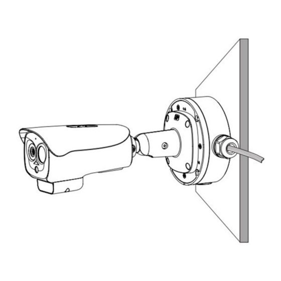
VIVOTEK Bi-spectrum network camera User Manual Fix Camera Step 4 Connect the multi-connector cable and monitor, loosen the screw 2 to adjust the position so that the camera face the monitored area. Tighten the screw 1 and screw 2. Adjust Image Screw 1 Screw 2 1.3.2 With Conduit Box... - Page 15 VIVOTEK Bi-spectrum network camera User Manual Step 2 Install the conduit box on the ceiling or wall and then fix the screws. Step 3 Take out the camera and use the screws provided in the conduit box to fix the camera on the mounting plate of junction box.
-
Page 16: Cable Connection
VIVOTEK Bi-spectrum network camera User Manual Step 5 Adjust the direction of the camera as shown in the pictures in step 4 and tighten screw 2. If the camera image needs to be adjusted, loosen screw 2, align the image to the position to be detected, and tighten screw 2 to complete the camera installation. - Page 17 VIVOTEK Bi-spectrum network camera User Manual Multi-connector Combination Cables Core of Cable Functions Network interface Connect to the standard Ethernet cable. Support PoE power supply. ALARM1 Alarm in/ alarm out 1 Brown: alarm OUT COM 1 Blue: alarm OUT 1 White: alarm IN COM 1 Green: alarm IN 1 ALARM 2...
- Page 18 VIVOTEK Bi-spectrum network camera User Manual supply. Audio Output Connect to the external audio device such as the voice box. Audio Input Input the audio signal and receives the analog audio signals from the sound pick-up device. RCA connector is supported.
-
Page 19: Quick Configuration
VIVOTEK Bi-spectrum network camera User Manual Quick Configuration 2.1 Login and Logout To access the web interface through Edge browser (IE Mode); Otherwise, some functions may be unavailable. Login system Step 1 Run VIVOTEK Shepherd or ONVIF Search Tool to find the IP address of your thermal camera. -
Page 20: Homepage Layout
VIVOTEK Bi-spectrum network camera User Manual ⚫ Access the web at Edge browser which the mode should switch to Reload in Internet Explorer mode. At browser “Setting > Default browser” page, Let Internet Explorer open sites in Microsoft Edge choose “Always (Recommenced)”; Allow sites to be reloaded in Internet Explorer mode (IE mode) choose “Allow”. - Page 21 VIVOTEK Bi-spectrum network camera User Manual Homepage Layout Elements on the Homepage Element Description Real-time Real-time videos are played in this area. You can also set video area sensor parameters. The two channels are displaying at the same time. Playback You can query the playback videos in this area.
-
Page 22: Changing The Password
VIVOTEK Bi-spectrum network camera User Manual Element Description : Interphone. : Sensor, or click right mouse button, more details please refer to chapter 4 and 5 : Snapshot. : Record video to local storage. When the device generates an alarm, the alarm icon is displayed. -
Page 23: Browse Video
VIVOTEK Bi-spectrum network camera User Manual ⚫ The change password page will be displayed if you don’t change the default password when you login the system for the first time. Step 2 Input the old password, new password, and confirm password. Step 3 Click OK. - Page 24 VIVOTEK Bi-spectrum network camera User Manual Adding a Trusted Site Step 2 In Microsoft Edge, choose Control Panel > Internet Options > Security > Customer level, and set Download unsigned ActiveX control and initialize and script ActiveX controls not marked as safe for scripting under ActiveX controls and plug-ins to Enable.
-
Page 25: Install Plugins
VIVOTEK Bi-spectrum network camera User Manual Configuring ActiveX Control and Plug-ins Step 3 Download and install the player control as prompted. ⚫ The login page is displayed when the control is loaded. ⚫ If you can view the live video immediately, you can ignore the steps of adding trust site. 2.4.1 Install Plugins A message “Download and install the new plugin”... -
Page 26: Setting Local Network Parameters
VIVOTEK Bi-spectrum network camera User Manual ⚫ Channel switch, click the live video, the red frame means the chosen channel. ⚫ During installing plugins, you need to close the browser, finish the installation, login the device again. 2.5 Setting Local Network Parameters Description Local network parameters include: ⚫... - Page 27 VIVOTEK Bi-spectrum network camera User Manual Local Network Parameters Parameter Description Setting IP Protocol IPv4 is the IP protocol that uses [Setting method] an address length of 32 bits. Select a value from the drop-down list box. [Default value] IPv4 DHCP The device automatically [Setting method]...
- Page 28 VIVOTEK Bi-spectrum network camera User Manual Parameter Description Setting Alternate DNS IP address of a domain server. [Setting method] Server If the preferred DNS server is Enter a value manually. faulty, the device uses the alternate DNS server to resolve domain names.
-
Page 29: Configuring Thermal
VIVOTEK Bi-spectrum network camera User Manual Configuring Thermal 3.1 Temperature Parameters Temperature parameters include temperature unit, ambient type, ambient temperature, cavity temperature, correctional coefficient, area temperature display mode, area temperature type, measure mode, area alarm interval and so on. Operation Procedure Step 1 Choose Configuration >Thermal >Temperature Parameters. - Page 30 VIVOTEK Bi-spectrum network camera User Manual Table 3-1 Temperature Parameters Parameter Description Setting Temperature Unit Celsius and Fahrenheit [Setting method] temperature units are available. Select a value from the drop-down list box. [Default value] Celsius Length units Meters and feet length units are [Setting method] available.
- Page 31 VIVOTEK Bi-spectrum network camera User Manual Parameter Description Setting Area Temperature The display position of [Setting method] Display Mode temperature information on the Select a value from the live-video image. drop-down list box. [Default value] Low left Font Border Enable to bold the font [Setting method] Enable or disable [Default value]...
- Page 32 VIVOTEK Bi-spectrum network camera User Manual Parameter Description Setting Temperature It depends on the device. [Setting method] range Different devices have different Select a value from the modes, there are two ranges, drop-down list box. such as -20 ℃ -150℃, -40 ℃- 150℃.
- Page 33 VIVOTEK Bi-spectrum network camera User Manual Parameter Description Setting Greater Prominent Enable that, the image will [Setting method] show the setting color if the Enter a value manually. temperature is higher than set Choose one color to value. show. Section Prominent Enable that, the image will [Setting method] show the setting color if the...
-
Page 34: Ambient Temperature
VIVOTEK Bi-spectrum network camera User Manual 3.2 Ambient Temperature Ambient Temperature Parameter of Ambient Temperature Parameter Description Setting Ambient Environment temperature of [Setting method] Temperature camera. Enter the temperature of ambient environment. [Default value] Cavity Temperature Set the ambient temperature, click “Apply”, click “Refresh”... - Page 35 VIVOTEK Bi-spectrum network camera User Manual Alarm Configuration Step 2 Set thermal alarm configuration and temperature measurement parameters according to the following tableError! Reference source not found.. Checking “Alarm” option in this alarm configuration to take effect. Alarm Configuration Parameter Description Setting Channel...
- Page 36 VIVOTEK Bi-spectrum network camera User Manual Parameter Description Setting Measure Mode Set at temperature parameter interface. Enable Tick the ID to enable the area [Setting method] measuring. Tick Name Area name of temperature area. [Setting method] Enter a value manually. Type Type of temperature area.
- Page 37 VIVOTEK Bi-spectrum network camera User Manual Parameter Description Setting Duration (1- Choose temperature rise alarm, [Setting method] 10S) set the duration. the temperature Enter a value manually. value rises within duration [Default value] setting, the alarm is triggered 1.00 successfully. Emission Rate The emission rate is the [Setting method]...
- Page 38 VIVOTEK Bi-spectrum network camera User Manual Parameter Description Setting Group ID The ID can be chosen into one of [Setting method] six groups, or no group. The Select a value from the group will be alarm following as drop-down list box. the next rules: A=The highest temperature of groups (the highest temperature...
- Page 39 VIVOTEK Bi-spectrum network camera User Manual Temperature Area Setting Interface 3. Click Apply, the message “Apply success” is displayed, and the temperature area is set successfully. ID 0 is the full screen; The area cannot be changed. : the lowest temperature of the full screen. :the highest temperature of the full screen.
-
Page 40: Privacy Zone Masking
VIVOTEK Bi-spectrum network camera User Manual 3.4 Privacy Zone Masking Privacy zone masking means that the camera will do not detect the temperature of that area. Up to 8 areas can be configured. Operation Procedure Step 1 Choose Configuration > Thermal > Privacy Zone Masking. Privacy Zone Masking Step 2 Enable the shield area. -
Page 41: Schedule Linkage
VIVOTEK Bi-spectrum network camera User Manual 3.5 Schedule Linkage Operation Procedure Step 1 Go to Configuration >Thermal > Schedule Linkage. Step 2 Choose the output channel. Step 3 Enable event linkage: “Alarm Record”, “SMTP”,”FTP upload”, audible alarm, flashlight alarm. Step 4 Set schedule linkage. Step 5 The message "Apply success"... -
Page 42: Parameter Description
VIVOTEK Bi-spectrum network camera User Manual ⚫ Alarm output: Users should connect the external alarm device (such as siren) to alarm output cables. The parameter can be set by going to “ Configuration > Alarm > Alarm Output”. Alarm Output Parameter Description Setting... - Page 43 VIVOTEK Bi-spectrum network camera User Manual Parameter Description Setting Alarm Output When the device receives I/O alarm [Setting method] Mode signals, the device sends the alarm Select a value from the information to an external alarm device drop-down list box. in the mode specified by this parameter.
- Page 44 VIVOTEK Bi-spectrum network camera User Manual ⚫ Alarm Record: Users insert the SD card in camera. The recording time is set at “ Configuration > Device Record > Record Policy” interface. SMTP: At “ Configuration > Network > SMTP” interface, users should set the ⚫...
- Page 45 VIVOTEK Bi-spectrum network camera User Manual Parameter Description Setting User Name User name of the mailbox for [Setting method] sending emails. Enter a value manually. Password Password of the mailbox for [Setting method] sending emails. Enter a value manually. Sender E- Mailbox for sending emails.
- Page 46 VIVOTEK Bi-spectrum network camera User Manual FTP Upload: At “ Configuration > Network > FTP Upload” interface, users ⚫ should set the parameters of FTP upload in advance. FTP Upload FTP Upload Parameters Parameter Description Setting FTP Upload Indicates whether to enable the [Setting method] FTP service.
- Page 47 VIVOTEK Bi-spectrum network camera User Manual Parameter Description Setting Media type The media type of sending to FTP, [Setting method] snapshot or video clip. Select a value from the drop-down list box. [Default value] Snapshot...
- Page 48 VIVOTEK Bi-spectrum network camera User Manual Audio Detect Alarm: At “ Configuration > Alarm > Audible Alarm Output” ⚫ interface, users should set the parameters of audible Alarm output in advance. Audible Alarm Output User can set the audio file manually. Click to upload the audio file(The type should be WAV, size must be less than 250 Kb, the bit rate should be 128 kbps.).
-
Page 49: Thermal Mapping
VIVOTEK Bi-spectrum network camera User Manual Upload Audio File Flashlight Alarm: At “Configuration > Thermal > Led Control Param” interface, set the flashlight alarm mode. The Display Mode choose mode 5 (When alarm triggered, the Led light will keep on for 20s), the Led light will be on when the alarm is triggered. - Page 50 VIVOTEK Bi-spectrum network camera User Manual Operation Procedure Step 1 Choose Configuration > Thermal >Thermal Mapping. Thermal Mapping Interface Step 2 Settings please refer to the following table0. Parameter of Thermal Mapping Parameter Description Setting Horizontal shift(%) Adjust horizontal position of area [Setting method] which is on visual image.
-
Page 51: Defect Pixel Correction
VIVOTEK Bi-spectrum network camera User Manual Parameter Description Setting Mapping point You need map three points at two [Setting method] channels. Points are correspond of each. Select from drop list . The three points should cover most areas, and two points are located in the diagonal display of the picture. - Page 52 VIVOTEK Bi-spectrum network camera User Manual Step 2 Click the white point at image, click Refresh to recover the defect pixel.
-
Page 53: Led Control Param
VIVOTEK Bi-spectrum network camera User Manual Step 3 Click Apply. The message "Apply success" is displayed, the system saves the settings. 3.8 LED Control Param Set the display mode and brightness of LED. - Page 54 VIVOTEK Bi-spectrum network camera User Manual Parameter Description Setting Display Mode There are four modes can be chosen. [Setting method] Open: the LED is always lighting. Select from drop-down list. Close: the LED is closed. Flicker: set the flicker interval, the LED will flicker as the set.
-
Page 55: Visible Channel Image Settings
VIVOTEK Bi-spectrum network camera User Manual Visible Channel Image Settings 4.1 Accessing Image Settings Procedure Step 1 Go to Configuration > Image Settings > Channel, and then select Channel 1. ⚫ All sensor configure can be modified at debug mode. Click in the lower left corner of Sensor Setting, and choose Debug Mode. -
Page 56: Mode
VIVOTEK Bi-spectrum network camera User Manual 4.2 Mode Step 1 Click and choose Debug Mode. Step 2 Choose the switch mode from the drop-down list. Step 3 Time mode: Set the Start Time, set the End Time. Step 4 Click Save, the message "Save succeed" is displayed, the system saves the settings. 4.3 Image... - Page 57 VIVOTEK Bi-spectrum network camera User Manual Parameter Description Configuration Method Brightness It indicates the total brightness of an image. As [Setting method] the value increases, the image becomes Drag the slider. brighter. [Default value] Sharpness It indicates the border sharpness of an image. [Setting method] As the value increases, the borders become Drag the slider.
-
Page 58: Scene
VIVOTEK Bi-spectrum network camera User Manual 4.4 Scene Scene Parameter Description Configuration Method Scene Indoor or outdoor. [Setting method] Select a value from the drop-down list. [Default value] Outdoor Mirror It is used to select the pixel location of [Setting method] an image. - Page 59 VIVOTEK Bi-spectrum network camera User Manual Parameter Description Configuration Method Exposure Mode The exposure modes include: [Setting method] Select a value from ⚫ Auto: The system performs auto exposure the drop-down list. based on the monitoring environment. [Default value] ⚫ Manual: You can set Shutter Setting to Auto fixed values manually.
- Page 60 VIVOTEK Bi-spectrum network camera User Manual 4.6 WB Parameter Description Configuration Method Mode It is used to display the real color of a [Setting method] monitoring scenario when the color temperature Select a value changes. from the drop- down list. ⚫...
-
Page 61: Daynight
VIVOTEK Bi-spectrum network camera User Manual 4.7 DayNight Parameter Description Configuration Method DayNight It can be set to Auto, Day Mode, Night Mode [Setting method] Mode and Timing. Select a value from the drop-down list. ⚫ Auto mode [Default value] The image color is adjusted based on the Auto day/night mode. -
Page 62: Noise Reduction
VIVOTEK Bi-spectrum network camera User Manual Trans (D to Day transit to night. [Setting method] Drag the slider. [Default value] Trans (N to Night transit to day. [Setting method] Drag the slider. [Default value] Delay [Setting method] Drag the slider. [Default value] IR LED Tick to enable the IR LED, there are two modes... -
Page 63: Enhance Image
VIVOTEK Bi-spectrum network camera User Manual Parameter Description Configuration Method 2D NR Auto /manual, default value is auto. [Setting method] By comparing and screening the images of the Drag the slider two frames before and after, the noise point strength. position is found out and gain control is carried [Default value] out on them. - Page 64 VIVOTEK Bi-spectrum network camera User Manual It indicates reverse bright points in the picture [Setting method] to black. As an effective approach to Drag the slider. recognize vehicle plate number at night, HLC [Default value] function can detect any spotlight diffused by object-vehicle and compensate it for obtaining clearer image.
-
Page 65: Thermal Channel Image Settings
VIVOTEK Bi-spectrum network camera User Manual Thermal Channel Image Settings 5.1 Accessing Image Settings Operation Procedure Go to “Configuration > Image Settings > Channel, and then select Channel 2. -
Page 66: Mode
VIVOTEK Bi-spectrum network camera User Manual 5.2 Mode Operation Procedure Step 1 In Image Settings page, go to Mode and then choose “Debug Mode”. Step 2 Go to “Mode” tab. Step 3 Choose “Switch Mode” from the drop-down list. Step 4 Time mode: Set Start Time and End Time. Step 5 Click Save. -
Page 67: Image
VIVOTEK Bi-spectrum network camera User Manual 5.3 Image Step 1 In Image Settings page, go to Mode and then choose “Debug Mode”. Step 2 Go to Image tab. Step 3 Drag the slider to adjust parameter of image. Step 4 Click Save. ⚫... -
Page 68: Scene
VIVOTEK Bi-spectrum network camera User Manual 5.4 Scene Step 1 In Scene tab. Step 2 Choose mirror mode from drop-list. Step 3 Click Save. ⚫ Mirror providing the selection of image pixel locations. ⚫ Normal: the image is not flipped. ⚫... - Page 69 VIVOTEK Bi-spectrum network camera User Manual Step 1 In Set Pseudocolor tab. Step 2 Choose Pseudo-color from drop-list. Step 3 Enable or disable the legend of temperature value. Step 4 Adjust location of Mix Stream.(Enable Mix Stream, at Configuration > Thermal > Temperature Parameters >...
-
Page 70: Ffc Control
VIVOTEK Bi-spectrum network camera User Manual 5.6 FFC Control Parameter Description Setting The internal of the thermal imaging camera may comprise the mechanical action correction mechanism that can periodically improve the image quality. This component is called flat field correction (FFC). When controlling the FFC, the FFC shields the sensor array, so that each portion of the sensor can collect uniform temperature fields (flat field). - Page 71 VIVOTEK Bi-spectrum network camera User Manual Parameter Description Setting ranges from 5 to 30 minutes. The temperature change of the camera is based on the temperatures collected by the internal temperature probe. The temperature of the camera sharply changes when the camera is powered on.
-
Page 72: Noise Reduction
VIVOTEK Bi-spectrum network camera User Manual 5.7 Noise Reduction Parameter Description Setting [How to set] Decrease the image 2DNR noise. Select from the drop-down list box. [How to set] Decrease the image 3DNR noise. Select from the drop-down list box. -
Page 73: Intelligent Analysis
VIVOTEK Bi-spectrum network camera User Manual Intelligent Analysis There are many kinds of intelligent analysis, such as Intrusion, Single Line Crossing, Double Line Crossing, Multi-Loitering, Retrograde, Enter Area, Leave Area. The parameters of these analysis alarm are roughly similar, so we will describe someone in detail as a reference. - Page 74 VIVOTEK Bi-spectrum network camera User Manual Step 2 Set all parameters for Intrusion. The table describes the specific parameters. Parameter Description Setting Channel Channel 1: visible. Choose one channel to set. Channel 2: thermal. Enable Enable the button to enable the alarm. [How to set] Click Enable to enable.
- Page 75 VIVOTEK Bi-spectrum network camera User Manual Parameter Description Setting Limit Type Effective alarms are set based on target [How to set] type, with options of Person or Car, Click to enable Limit Target Person, Car. Type. [Default value] When the device is used indoors, because of small space and large targets, to avoid wrong alarms are triggered b person even if car is selected, it is...
- Page 76 VIVOTEK Bi-spectrum network camera User Manual Step 3 Set a deployment area. Move the cursor to the drawing interface and click to generate a point, move the cursor to draw a line, and then click to generate another point. This is how a line is generated.
-
Page 77: Single Line Crossing
VIVOTEK Bi-spectrum network camera User Manual 6.2 Single Line Crossing Procedure Step 1 Select Configuration > Intelligent Analysis > Single Line Crossing. Step 2 Set all parameters for the Single Line Crossing. Parameter Description Setting Channel Channel 1: visible. [How to set] Channel 2: thermal. - Page 78 VIVOTEK Bi-spectrum network camera User Manual Parameter Description Setting Enable Enable the button to enable [How to set] the alarm. Click Enable to enable. [Default value] Limit Type Effective alarms are set [How to set] based on target type, with Click to enable Limit options of Person or Car, Target Type.
- Page 79 VIVOTEK Bi-spectrum network camera User Manual Parameter Description Setting SMTP Enable the button to enable [How to set] SMTP server. Click to enable SMTP. [Default value] FTP Upload Enable the button to enable [How to set] File Transfer Protocol. Click to enable FTP. [Default value] Video Stream Draw Enable this option to show...
-
Page 80: Double Line Crossing
VIVOTEK Bi-spectrum network camera User Manual 6.3 Double Line Crossing Procedure Step 1 Select Configuration > Intelligent Analysis > Double Line Crossing Step 2 Set all parameters for the Double Line Crossing Parameter Description Setting Enable Enable the button to enable the alarm. [How to set] Click to enable. - Page 81 VIVOTEK Bi-spectrum network camera User Manual Parameter Description Setting Limit Type Effective alarms are set based on target type, with [How to set] options of Person or Car, person, car. When the Click to enable device is used indoors, because of small space and Limit Target large targets, alarms are triggered by person Type.
-
Page 82: Enter Area / Leave Area
VIVOTEK Bi-spectrum network camera User Manual Draw a line: Move the cursor to the drawing interface, hold down the left mouse button, and move the cursor to draw two lines. When you release the left mouse button, two numbered virtual fences are generated. Choose either of the Double Line Crossing to set the direction to Positive or Reverse. - Page 83 VIVOTEK Bi-spectrum network camera User Manual Leave Area Step 2 Set all parameters for Enter Area / Leave Area.
- Page 84 VIVOTEK Bi-spectrum network camera User Manual Step 3 Set a deployment area. Move the cursor to the drawing interface and click to generate a point, move the cursor to draw a line, and then click to generate another point. This is how a line is generated. In this way, continue to draw lines to form any shape, and right-click to finish line drawing.
-
Page 85: Advanced Intelligent Analysis
VIVOTEK Bi-spectrum network camera User Manual Advanced Intelligent Analysis At the advanced intelligent analysis interface, users can set the parameters of smoker detection, smoke and flame detection, and fire spot detection. Enable the linkage actions, the alarm information can be sent to user by the linkage. The advanced intelligent analysis can be used for detecting the smoking, e.g., if someone is smoking in an area where smoking is forbidden. - Page 86 VIVOTEK Bi-spectrum network camera User Manual Step 2 Set all parameters for Smoker Detection. Parameter Description Setting Enable At thermal channel, Enable the button to [How to set] enable the alarm. Click Enable to enable. [Default value] Output Channel If you check to set the Output Channel [How to set] and the device is connected to an Click to select an ID.
- Page 87 VIVOTEK Bi-spectrum network camera User Manual Parameter Description Setting Flashlight alarm Enable, when it is triggered alarm, it [How to set] flashes the light. But when users set the Click to enable Flashlight display mode to Mode 5 at Alarm. “Configuration >...
-
Page 88: Smoke And Flame Detection
VIVOTEK Bi-spectrum network camera User Manual 7.2 Smoke and Flame Detection Description The smoke flame detection function refers to that an alarm is generated when something is smoking or generating flame in the deployment area. Procedure Step 1 Select Configuration > Advanced Intelligent Analysis > Smoke and Flame Detection. - Page 89 VIVOTEK Bi-spectrum network camera User Manual Parameter Description Setting Enable At thermal channel, Enable the button to [How to set] enable the alarm. Click Enable to enable. [Default value] Output Channel If you check to set the Output Channel [How to set] and the device is connected to an Click to select an ID.
-
Page 90: Fire Spot Detection
VIVOTEK Bi-spectrum network camera User Manual Parameter Description Setting Video Stream Enable this option to show the detection [How to set] Draw Line zone on live video. Click to enable Video Stream Draw Line [Default value] Step 3 Set a deployment area. Move the cursor to the drawing interface and click to generate a point, move the cursor to draw a line, and then click to generate another point. - Page 91 VIVOTEK Bi-spectrum network camera User Manual Step 2 Set all parameters for Fire Spot Detection. Parameter Description Setting Enable At thermal channel, Enable the button to [How to set] enable the alarm. Click Enable to enable. [Default value] Output Channel If you check to set the Output Channel [How to set] and the device is connected to an...
- Page 92 VIVOTEK Bi-spectrum network camera User Manual Parameter Description Setting Flashlight alarm Enable, when it is triggered alarm, it [How to set] flashes the light. But when users set the Click to enable Flashlight display mode to Mode 5 at Alarm. “Configuration >...
- Page 93 VIVOTEK Bi-spectrum network camera User Manual Set Deployment Area ⚫ A drawn line cannot cross another one, or the line drawing fails. ⚫ Any shape with 8 sides at most can be drawn. ⚫ The quantity deployment areas is up to 8. Step 4 Set actions accordingly.
-
Page 94: Ai Multi-Object
VIVOTEK Bi-spectrum network camera User Manual AI Multi-object Step 1 At “ Configuration > AI Multiobject ” interface, user can enable full-body detection, vehicle detection to detect the person and vehicle. Step 2 Set the parameters of AI multiobject. Parameter Description How to set Channel... - Page 95 VIVOTEK Bi-spectrum network camera User Manual Parameter Description How to set detection appear in live video. The detection frame is yellow. The range of snap image, there are three type, Confidence such as high, mid and low. The higher the Choose from Coefficient confidence, the better the snap quality and the...
-
Page 96: Alarm Setting
VIVOTEK Bi-spectrum network camera User Manual Alarm Setting 9.1 Alarm Output Procedure Step 1 Select Configuration > Alarm > Alarm Output to access the Alarm Output. Step 2 Set alarm output of channel, name, enable valid signal and alarm time choose alarm output mode. -
Page 97: Disk Alarm
VIVOTEK Bi-spectrum network camera User Manual 9.2 Disk Alarm Procedure Step 1 Select Configuration > Alarm > Disk Alarm to access the disk alarm setting. Step 2 Enable the disk full alarm, when the disk is full it will alarm. Step 3 Set alarm interval and tick output channel. -
Page 98: I/O Alarm Linkage
VIVOTEK Bi-spectrum network camera User Manual 9.4 I/O Alarm Linkage Procedure Step 1 Select Configuration > Alarm > I/O Alarm Linkage Step 2 Choose alarm input and trigger mode, set name, enable other linkages such as alarm input, Alarm Record SMTP, FTP upload, IR Cut and flashlight alarm. Step 3 Set alarm schedule, choose the duration of linkage. -
Page 99: Audio Abnormal Detection
VIVOTEK Bi-spectrum network camera User Manual Step 2 Choose channel and enable the motion alarm, set alarm interval and sensitivity, enable other linkages such as SMTP, FTP upload and motion detect stream. Step 3 Set motion alarm schedule, Step 4 Click Apply to save the settings, click Refresh will return last settings. ---End 9.6 Audio Abnormal Detection Procedure... - Page 100 VIVOTEK Bi-spectrum network camera User Manual Step 2 Enable the audio abnormal detection, enable sudden rise or sudden drop. Step 3 Tick the output channel, enable alarm record, SMTP, FTP upload. Step 4 Set alarm schedule, choose the duration of linkage. Step 5 Click Apply to save the settings, click Refresh will return last settings.
-
Page 101: Other Web Configurations
VIVOTEK Bi-spectrum network camera User Manual Other Web Configurations 10.1 Device Information You can view the information about device at Device Information. 10.2 Stream 10.2.1 Base Stream Step 1 Choose Configuration > Stream >Base Stream. -
Page 102: Roi
VIVOTEK Bi-spectrum network camera User Manual Channel 2 (Thermal Channel) Stream Step 2 Choose channel, stream ID, video encode type, video encode level, audio encode type, resolution, frame rate, frame interval, bit rate type and bit rate from all drop list. Step 3 Set name of base stream, enable smart encode. -
Page 103: Snapshot
VIVOTEK Bi-spectrum network camera User Manual Figure 10-1 ROI Interface Step 2 Click Draw and the frame is showing, adjust the position of frame to set ROI area. Step 3 Click Apply. The message "Apply success" is displayed, the system saves the settings. ---End 10.2.3 Snapshot Step 1 Choose Configuration >... -
Page 104: Device
VIVOTEK Bi-spectrum network camera User Manual Step 2 Choose snapshot resolution and snapshot quality from drop list. Step 3 Click Apply. The message "Apply success" is displayed, the system saves the settings. ---End 10.3 Device You can set local network, device port, data and time, camera, OSD, Audio input, Audio output, CVBS, system, voice denoise and software licenses. -
Page 105: Privacy Masking
VIVOTEK Bi-spectrum network camera User Manual 10.4 Privacy Masking Choose Configuration > Privacy masking. You can set up a privacy mask by drawing an area and then clicking on Add. Modify the color if needed. Adding more privacy masks if needed. 10.5 Network Service Choose Configuration >... -
Page 106: Privacy Manager
VIVOTEK Bi-spectrum network camera User Manual Description If the device is connected to a router or switch with a QOS function, and the priority rule of the corresponding mark is configured on the network device, the network device will preferentially pass the data packet of the corresponding mark. Procedure Step 1 Choose Configuration >... -
Page 107: Protocol
VIVOTEK Bi-spectrum network camera User Manual 10.7 Protocol Choose Configuration > Protocol. You can set protocol information, security and multicast parameter. -
Page 108: Device Log
VIVOTEK Bi-spectrum network camera User Manual 10.8 Device Log Choose Configuration > Device Log. You can view operation log and alarm log, or collect all log information. 10.9 Maintenance Choose configuration > maintenance. You can restart, update, reserve IP setting and restore to factory default. -
Page 109: Local Config
VIVOTEK Bi-spectrum network camera User Manual 10.10 Local Config When users choose the plugin to play live video, this function can be set. Choose Configuration > Local Config. You can change the save path of snapshot and local record, choose the playback performance. -
Page 110: A Troubleshooting
VIVOTEK Bi-spectrum network camera User Manual A Troubleshooting Common Trouble Possible Cause Solution Unable to access Network is not Connect the network cable of the camera to the the web connected. PC to check whether the network cable is in good contact. - Page 111 VIVOTEK Bi-spectrum network camera User Manual Common Trouble Possible Cause Solution An error occurs in The data in the cache Delete the cache of browser. The steps are as accessing the web of browser is not follows (taking Edge as an example): of the device after updated in time.
Need help?
Do you have a question about the VIVOTEK TB9333-E and is the answer not in the manual?
Questions and answers