
Related Manuals for DELTA GROUP Vivotek CD9381-HNTV


Summary of Contents for DELTA GROUP Vivotek CD9381-HNTV
- Page 1 CD9381-HNVF2 CD9381-HNTV Corner Dome Network Camera User ’s Manual 5MP • WDR Pro • SNV • 940nm IR • IK10+ • IP67 • Anti-Ligature • Anti-Grip Rev. 1.0 Rev. 1.0...
-
Page 2: Table Of Contents
VIVOTEK Table of Contents Overview..................................4 Revision History ..............................4 Read Before Use ..............................5 Package Contents ..............................5 Symbols and Statements in this Document ......................5 Physical Description ............................10 LED Definition ..............................11 Hardware Installation ............................12 Software Installation ............................. 23 Network Deployment .............................. - Page 3 VIVOTEK Network > QoS (Quality of Service) ........................ 105 ............107 Network > SNMP (Simple Network Management Protocol) Network > FTP ..............................108 Bonjour ................................109 Security > User accounts ........................... 110 Security > HTTPS (Hypertext Transfer Protocol over SSL) ..............112 Security >...
-
Page 4: Overview
VIVOTEK Overview VIVOTEK’s CD9381-HNVF2 is a vandal-proof network camera specifically designed for prisons and correctional facilities. With up to 30 fps at 5-Megapixel resolution, 940nm IR illuminators, two-way audio, and available in either fixed lens (-HNVF2) or vari-focal (-HNTV), the camera is the most feature rich prison cell surveillance camera available today. -
Page 5: Read Before Use
VIVOTEK Read Before Use The use of surveillance devices may be prohibited by law in your country. The Network Camera is not only a high-performance web-ready camera but can also be part of a flexible surveillance system. It is the user’s responsibility to ensure that the operation of such devices is legal before installing this unit for its intended use. - Page 6 VIVOTEK NOTE: Camera Hardware Preventative Maintenance: 1. Visual inspection of all major components including accessories, cabling and connections where accessible for signs of deterioration or damage. 2. Check and clean cameras, lenses and housings inside and out as needed. • Please do not scratch, damage, or leave fingerprints on the dome/front cover and/or lens because this may decrease image quality.
- Page 7 VIVOTEK IMPORTANT: 1. The product must be installed and protected in a location that is not easily accessible, and is away from impacts or heavy vibration. For example, at the location where the surveillance cameras are looking down or installed at high positions such as on a wall, or at least 3 meters above the ground.
- Page 8 VIVOTEK IMPORTANT: For some customers who already have their own web site or web control application, the Network Camera/Video Server can be easily integrated through URL syntax. This section specifies the external HTTP-based application programming interface. The HTTP-based camera interface provides the functionality to request a single image, control camera functions (PTZ, output relay etc.), and get and set internal parameter values.
- Page 9 VIVOTEK Hardware Reset The reset button is used to reset the system or restore the factory default settings. Sometimes resetting the system can return the camera to normal operation. If the system problems remain after reset, press the reset button longer to restore the factory settings and install again. Reset: Press and release the recessed reset button with a straightened paper clip.
-
Page 10: Physical Description
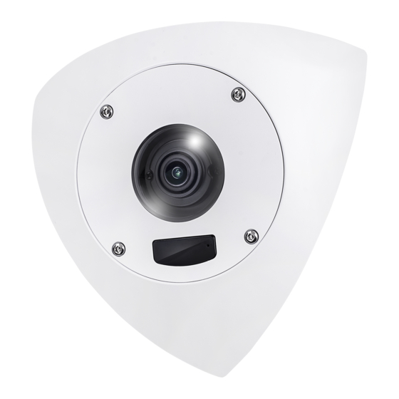
VIVOTEK Physical Description Outer View Lens IR window Microphone Inner View Rubber seal for Ethernet Rubber seal for I/O combo Reset button MicroSD card slot RJ45 LAN I/O combo port connector Microphone Case open detection micro IR LEDs switch 10 - User's Manual... -
Page 11: Led Definition
VIVOTEK LED Definition Item LED Status Description Steady Power on and system booting LED off Powered off Steady + blinking Green every 1 sec. (Green Network heartbeat LED on for 1 sec and off for another) Steady Green LED off Network disconnected Blinking every 0.15 sec. -
Page 12: Hardware Installation
VIVOTEK Hardware Installation 1. Jot down the camera’s MAC address for later reference. Network Camera Model No: XXXXXX MAC: 0002D1083236 This device complies with part 15 of the FCC Rules. Operation is subject to the following two conditions: (1) this device may not cause harmful interference, and (2) this device must accept any interference received, including interference that may cause undesired operation. - Page 13 VIVOTEK 3. Use the base bracket as a template, and draw drill holes using a pencil. The camera is designed to be installed to a 3-sided corner of a room. 4. Drill 6 mounting holes (8mm in diameter) into the walls and ceiling. If preferred, drill a cable routing hole.
- Page 14 VIVOTEK 5. With threaded anchors in walls, secure the bracket to walls using hex nuts and washers. 6. Route cables through the wall and the bracket. 14 - User's Manual...
- Page 15 VIVOTEK 7. Install rubber gasket to the Ethernet cable. Pass the cable through the routing hole on camera and install the gasket. 8. Install the waterproof cable gland to the Ethernet cable. User's Manual - 15...
- Page 16 VIVOTEK If I/O cable is preferred, intall the I/O cable. 16 - User's Manual...
- Page 17 VIVOTEK Remove the original rubber seal. Install and connect the I/O cable connector. DI/DO AC 24V DC 12V Audio IN Audio OUT User's Manual - 17...
- Page 18 VIVOTEK 1. Stretch the waterproof tape by twice its length and wind around the cables. 2. The tape should overlap the cable joints by 20mm. 3. All connectors, whether they are used or not, should be waterproof. Cable molding Layer - Self-fusing tape or electric tape 18 - User's Manual...
- Page 19 VIVOTEK When installing the rubber seal, pull the cable slightly outward to ensure it is waterproof. Please do not leave the edge of center hole folded toward the inside of the camera. Doing so will compromise its waterproof feature. 9. Insert a MicroSD card. The Micro B USB port can be used to remotely connect a WiFi dongle and to a notebook for the initial image setup.
- Page 20 VIVOTEK 10. When cabling connection is done, secure the camera to bracket. 20 - User's Manual...
- Page 21 VIVOTEK 11. Replace the desiccant bag with the one that comes with the shipping package. 12. The camera lens can be tilted up and down. Adjust the shooting direction CD9381-HNTV only +15° -15° User's Manual - 21...
- Page 22 VIVOTEK Adjust the lens module so that the field of view can cover the entire room. V FOV 90° 22 - User's Manual...
-
Page 23: Software Installation
VIVOTEK Software Installation 22. Install the Shepherd utility, which helps you locate and configure your Network Camera in the local network. If your camera comes without the CD, go to VIVOTEK’s website, and locate the utility in the Downloads > Software page. 22-1. - Page 24 VIVOTEK 22-3. The program will search for all VIVOTEK network devices on the same LAN. 22-4. After a brief search, the installer window will prompt. Click on the MAC and model name that matches the one printed on the product label. You can then double-click on the address to open a management session to the Network Camera.
- Page 25 VIVOTEK Forceful Password Configuration 23. The first time you log in to the camera, the firmware will prompt for a password configuration for security concerns. 23-1. Since your camera is used for the first time, there is no password. Enter “root” as the user name, and nothting for the password.
- Page 26 VIVOTEK Some, but not all special ASCII characters are supported: !, $, %, -, ., @, ^, _, and ~. You can use them in the password combination. 23-3. Another prompt will request for the password you just configured. Enter the password and then you can start configure your camera and see the live view.
- Page 27 VIVOTEK Cybersecurity Once you open the web console, enter Configuration > Applications > Package management, and click on Trend Micro IoT Security. Turn on the protection to fend off cyber attacks. In here, you can let the camera automatically update the virus codes or manually update the virus codes.
- Page 28 VIVOTEK 15. When ensured that the field of view suits your need, install the top cover. LED Definitions Item LED status Description Steady Powered and system booting, or network failed LED off Power off Green LED off Network is disconnected Steady Green LED blinks every 1...
-
Page 29: Network Deployment
VIVOTEK Network Deployment Setting up the Network Camera over the Internet There are several ways to set up the Network Camera over the Internet. The first way is to set up the Network Camera behind a router. The second way is to utilize a static The third way is to use PPPoE. - Page 30 VIVOTEK For example, your router and IP settings may look like this: Device IP Address: internal IP Address: External Port (Mapped port on the port router) Public IP of router 122.146.57.120 LAN IP of router 192.168.2.1 Camera 1 192.168.2.10:80 122.146.57.120:8000 Camera 2 192.168.2.11:80 122.146.57.120:8001...
- Page 31 VIVOTEK Internet connection with static IP Choose this connection type if you are required to use a static IP for the Network Camera. Please refer to LAN configuration on page 90 for details. Internet connection via PPPoE (Point-to-Point over Ethernet) Choose this connection type if you are connected to the Internet via a DSL Line.
- Page 32 VIVOTEK NOTE: 1. If you encounter problems with displaying live view or the onscreen plug-in control, you may try to remove the plug-ins that might have been installed on your computer. Remove the following folder: C:\Program Files (x86)\Camera Stream Controller\. 2.
-
Page 33: Accessing The Network Camera
VIVOTEK Accessing the Network Camera This chapter explains how to access the Network Camera through web browsers, RTSP players, 3GPP-compatible mobile devices, and VIVOTEK recording software. Using Web Browsers IMPORTANT: • Currently the Network Camera utilizes 32-bit ActiveX plugin. You CAN NOT open a management/view session to the camera using a 64-bit IE browser. - Page 34 VIVOTEK Tips: 1. The onscreen Java control can malfunction under the following situations: A PC connects to different cameras that are using the same IP address (or the same camera running different firmware versions). Removing your browser cookies will solve this problem. 2.
- Page 35 VIVOTEK NOTE: 1. By default, your Network Camera is not password-protected. To prevent unauthorized access, it is highly recommended to configure a password for your camera later. For more information about how to enable password protection, please refer to Security on page 110. 2.
-
Page 36: Using Rtsp Players
VIVOTEK Using RTSP Players To view the streaming media using RTSP players, you can use one of the following players that support RTSP streaming. VLC media player VLC media player 1. Launch the RTSP player. 2. Choose File > Open URL. A URL dialog box will pop up. mpegable Player 3. -
Page 37: Using 3Gpp-Compatible Mobile Devices
VIVOTEK Using 3GPP-compatible Mobile Devices To view the streaming media through 3GPP-compatible mobile devices, make sure the Network Camera can be accessed over the Internet. For more information on how to set up the Network Camera over the Internet, please refer to Setup the Network Camera over the Internet on page To utilize this feature, please check the following settings on your Network Camera: 1. -
Page 38: Using Vivotek Recording Software
VIVOTEK Using VIVOTEK Recording Software Visit our website for download the VAST recording software that provides simultaneous monitoring and video recording for multiple Network Cameras. Please install the recording software; then launch the program to add the Network Camera to the Channel list. For detailed information about how to use the recording software, please refer to the user’s manual of the software or download it from http://www.vivotek.com. -
Page 39: Main Page
VIVOTEK Main Page This chapter explains the screen elements on the main page. It is composed of the following sections: VIVOTEK INC. Logo, Host Name, Camera Control Area, Configuration Area, and Live Video Window. VIVOTEK logo Configuration Resize Buttons Area Host name Camera Control Panel... - Page 40 VIVOTEK Camera Control Area Profile mode: 3 pre-configured streaming profiles are provided through here: Max. view, Recording view, Live view. Each mode features a different stream source (channel), resolution, multicast, and metadata configuration. The profiles can be configured in Configuration > Media > Media profiles. Manual Trigger: Click to manually enable or disable an event trigger.
- Page 41 VIVOTEK Pan /Tilt /Zoom speed: Adjust the speed of these controls when exerted: Pan speed Tilt speed Zoom speed Panoramic speed Slower Faster Configuration Area Client Settings: Click this button to access the client setting page. For more information, please refer to Client Settings on page 45.
- Page 42 VIVOTEK ■ The following window is displayed when the video mode is set to MJPEG: Video Title Time Video (HTTP-V) 2015/03/10 17:08:56 Title and Time Video 17:08:56 2015/03/10 Video Control Buttons Video Title: The video title can be configured. For more information, please refer to Media > Image on page 61.
- Page 43 VIVOTEK Live Video Window ■ The following window is displayed when the video mode is set to H.265 or H.264: Video Title: The video title can be configured. For more information, please refer to Video settings on page 77. H.264 Protocol and Media Options: The transmission protocol (TCP or UDP, etc.)and media options for H.265 or H.264 video streaming.
- Page 44 VIVOTEK Start MP4 Recording: Click this button to record video clips in MP4 file format to your computer. Press the Stop MP4 Recording button to end recording. When you exit the web browser, video recording stops accordingly. To specify the storage destination and file name, please refer to MP4 Saving Options on page 46 for details.
-
Page 45: Client Settings
VIVOTEK Client Settings This chapter explains how to select the stream transmission mode and saving options on the local computer. When completed with the settings on this page, click Save on the page bottom to enable the settings. H.265 / H.264 Protocol Options Select to stream video or audio data or both. -
Page 46: Mp4 Saving Options
VIVOTEK MP4 Saving Options Users can record live video as they are watching it by clicking the “Start MP4 Recording” button on the main page. Here, you can specify the storage destination and file name. Folder: Specify a storage destination for the recorded video files. File name prefix: Enter the text that will be appended to the front of the video file name. -
Page 47: Configuration
VIVOTEK Configuration Click Configuration on the main page to enter the camera setting pages. Note that only Administrators can access the configuration page. The following is the interface of the main page: Navigation Area Configuration List Firmware Version Each function on the configuration list will be explained in the following sections. The Navigation Area provides access to all different views from the Home page (for live viewing), Configuration page, and multi-language selection. -
Page 48: System > General Settings
VIVOTEK System > General settings This section explains how to configure the basic settings for the Network Camera, such as the host name and system time. It is composed of the following two columns: System and System Time. System Host name: Enter a desired name for the Network Camera. The name will be displayed at the top center of the main page. - Page 49 VIVOTEK System time Keep current date and time: Select this option to preserve the current date and time of the Network Camera. The Network Camera’s internal real-time clock maintains the date and time even when the power of the system is turned off. Synchronize with computer time: Select this option to synchronize the date and time of the Network Camera with the local computer.
- Page 50 VIVOTEK Western Argentina Summer Time (WARST) is 3 hours behind the prime meridian all year. There is a dummy fall-back transition on December 31 at 25:00 daylight saving time (i.e., 24:00 standard time, equivalent to January 1 at 00:00 standard time), and a simultaneous spring- forward transition on January 1 at 00:00 standard time, so daylight saving time is in effect all year and the initial WART is a placeholder.
-
Page 51: System > Homepage Layout
VIVOTEK System > Homepage layout This section explains how to set up your own customized homepage layout. General settings This column shows the settings of your hompage layout. You can manually select the background and font colors in Theme Options (the second tab on this page). The settings will be displayed automatically in this Preview field. - Page 52 VIVOTEK Theme Options Here you can change the color of your homepage layout. There are three types of preset patterns for you to choose from. The new layout will simultaneously appear in the Preview field. Click Save to enable the settings.
- Page 53 VIVOTEK ■ Follow the steps below to set up a custom homepage: 1. Click Custom on the left column. 2. Click to select a color on on the right column. Color Selector Custom Pattern 3. The palette window will pop up as shown below. 4.
-
Page 54: System > Logs
VIVOTEK System > Logs This section explains how to configure the Network Camera to backup system log to a remote server. Log server settings Follow the steps below to set up the remote log: 1. Select Enable remote log. 2. In the IP address text box, enter the IP address of the remote server. 2. - Page 55 VIVOTEK You can install the included VAST recording software, which provides an Event Management function group for delivering event messages via Emails, GSM short messages, onscreen event panel, or to trigger an alarm, etc. For more information, refer to the VAST User Manual. VIVOTEK Network Cameras Internet 3G Cell phone...
- Page 56 VIVOTEK Access log Access log displays the access time and IP address of all viewers (including operators and administrators) in a chronological order. The access log is stored in the Network Camera’s buffer area and will be overwritten when reaching a certain limit. Set Parameter log VADP log contains the history of changes made to system parameters such as recording, imaging parameters, and all other parameters.
-
Page 57: System > Parameters
VIVOTEK System > Parameters The View Parameters page lists the entire system’s parameters in an alphabetical order. If you need technical assistance, use a text-editor program to copy and save the parameters listed on this page. Send the parameter text file to VIVOTEK’s technical support. User's Manual - 57... -
Page 58: System > Maintenance
VIVOTEK System > Maintenance This chapter explains how to restore the Network Camera to factory default, upgrade firmware version, etc. General settings > Upgrade firmware This feature allows you to upgrade the firmware of your Network Camera. It takes a few minutes to complete the process. - Page 59 VIVOTEK General settings > Restore This feature allows you to restore the Network Camera to factory default settings. Network: Select this option to retain the Network Type settings (please refer to Network Type on page 90). Daylight Saving Time: Select this option to retain the Daylight Saving Time settings (please refer to Import/Export files below on this page).
- Page 60 VIVOTEK The following message is displayed when attempting to upload an incorrect file format. Export language file: Click to export language strings. VIVOTEK provides nine languages: English, Deutsch, Español, Français, Italiano, 日本語, Português, 簡体中文, and 繁體中文 . Update custom language file: Click Browse… and specify your own custom language file to upload. Export configuration file: Click to export all parameters for the device and user-defined scripts.
-
Page 61: Media > Image
VIVOTEK Media > Image This section explains how to configure the image settings of the Network Camera. It is composed of the following tabbed windows: General settings, Image settings, Exposure, and Privacy mask, and Pixel Calculator. General settings Video title: Enter a name that will be displayed on the title bar of the live video as well as the view cell on the VAST recording software. - Page 62 VIVOTEK Color: Select to display color or black/white video streams. Power line frequency: Set the power line frequency consistent with local utility settings to eliminate image flickering associated with fluorescent lights. Video orientation: Flip - vertically reflect the display of the live video; Mirror - horizontally reflect the display of the live video.
- Page 63 VIVOTEK ■ Synchronize with digital input The Network Camera automatically removes the IR cut filter when a digital input is triggered, for example, when the camera is accompanied by an external IR light that comes with its own sensor and provides a signal to the camera.
- Page 64 VIVOTEK Illuminators Turn on built-in IR illuminator in night mode Select this to turn on the camera’s onboard IR illuminator when the camera detects low light condition and enters the night mode. Turn on external IR illuminator in night mode Select which DO (digital output) you use to trigger an external IR illuminator.
- Page 65 VIVOTEK Tips: If there is an object in close proximity, the IR lights reflected back from it can mislead the Smart IR’s calculation of light level. To solve this problem, you can place an “Exposure Exclude” window on an unavoidable object in the Exposure setting window. See page 69 for how to do it.
-
Page 66: Image Settings
VIVOTEK Image settings On this page, you can tune the White balance, Image adjustment and related parameters. You can configure two sets of preferred settings: one for normal situations, the other for special situations, such as a schedule mode. Quality: select from the pull-down menu the image quality of the current live view. White balance: Adjust the value for the best color temperature. - Page 67 VIVOTEK ■ Sharpness: Adjust the image sharpness level, which ranges from 0% to 100%. ■ Gamma curve: Adjust the image sharpness level, which ranges from 0.45 to 1, from Detailed to Contrast. You may let firmware Optimize your display or select the Manual mode, and pull the slide bar pointer to change the preferred level of Gamma correction towards higher contrast or towards the higher luminance for detailed expression for both dark and lighted areas of an image.
-
Page 68: Exposure
VIVOTEK Exposure On this page, you can configure the Exposure measurement window, Exposure level, Exposure mode, Exposure time, Gain control, and Day/Night mode settings. Quality: select the pull-down menu to configure the image quality of the current display. Measurement Window: This function allows users to set measurement window(s) for low light compensation. - Page 69 VIVOTEK The inclusive window refers to the “weighted window“; the exclusive window refers to the “ignored window.“ It adopts the weighted averages method to calculate the value. The inclusive windows have a higher priority. You can overlap these windows, and, if you place an exclusive window within a larger inclusive window, the exclusive part of the overlapped windows will be deducted from the inclusive window.
- Page 70 VIVOTEK ■ Exposure time: you can split the round pointers on the Exposure time and Gain control slide bars into two halves and drag them on the bars to designate a range of values in which firmware can automatically adapt to. Note that Firmware will then automatically tune the Gain, Exposure time, and Iris opening within the ranges you specified.
- Page 71 VIVOTEK You can click Restore to recall the original settings without incorporating the changes. When completed with the settings on this page, click Save to enable the settings. If you want to configure another sensor setting for a specific lighting condition for a specific period of time in a day, please click Profile mode to open the Profile of exposure settings page as shown below.
- Page 72 VIVOTEK Focus Focus here refers to the Remote Focus, applicable to Network Cameras that are equipped with a stepping motor lens. The automated focus adjustment function eliminates the needs to physically adjust camera focus. In an outdoor deployment consisting of a large number of cameras, the auto focus function can be very helpful when these cameras become out of focus after days or weeks of operation.
- Page 73 VIVOTEK 5. Wait for the scan to complete. After a short while, the clearest image obtained should be displayed and the optimal focus range achieved. Use the arrow marks on the sides to fine-tune the focus if you are not satisfied with the results. You may still need to use the arrow marks to fine-tune the focus depend- ing on the live image on your screen.
-
Page 74: Privacy Mask
VIVOTEK Privacy mask Click Privacy Mask to open the configuration page. On this page, you can block out certain sensitive zones to address privacy concerns. ■ To configure the privacy mask windows, follow the steps below: 1. Click New to add a new window. A text box will appear allowing you to enter a name for the mask. 2. -
Page 75: Pixel Calculator
VIVOTEK Pixel Calculator Click the Add button at the lower screen to create a pixel calculator window. Place your cursor on the window to move it to an area of your interest, and change the size of window to fit the area of interest. Once they are drawn, the numbers of pixels on the sides of windows will appear. - Page 76 VIVOTEK Take the following into consideration when using this feature: 1. Operational requirement: Identify a human or a human face. 2. Why human face? There are less variances in the size of a face than that for limbs and body. Human face is normally 16cm wide.
-
Page 77: Media > Video
VIVOTEK Media > Video Mode The applicable video modes include: ■ 5-Megapixel (4:3) (max. 30fps)(WDR Pro): If the need should arise for a high contrast lighting environment, select this mode with the WDR Pro feature. ■ 4-Megapixel (16:9) (max. 30fps)(WDR Pro): If the need should arise for a high contrast lighting environment, select this mode with the WDR Pro feature. - Page 78 VIVOTEK Click the stream item to display the detailed information. This Network Camera offers real-time H.265, H.264 and MJPEG compression standards (dual Codec) for real-time viewing. If the H.265 H.264 mode is selected, the video is streamed via RTSP protocol. There are several parameters for you to adjust the video performance: ■...
- Page 79 VIVOTEK ■ Maximum frame rate This limits the maximum refresh frame rate per second. Set the frame rate higher for smoother video quality and for recognizing moving objects in the field of view. If the power line frequency is set to 50Hz, the frame rates are selectable at 1fps, 2fps, 3fps, 5fps, 8fps, 10fps, 15fps, 20fps, and 25fps.
- Page 80 VIVOTEK Smart stream III ■ Dynamic Intra frame period High quality motion codecs, such as H.265 or H.264, utilize the redundancies between video frames to deliver video streams at a balance of quality and bit rate. The encoding parameters are summarized and illustrated below. The I-frames are completely self- referential and they are largest in size.
- Page 81 VIVOTEK With the H.265 codec in an optimal scenario and when Dynamic Intra frame is combined with the Smart Stream function, an 80% of bandwidth saving can be achieved compared with using H.264 without enabling these bandwidth-saving features. ■ Smart FPS In a static scene, the algorithm puts old frames in queue when no motions occur in scene.
- Page 82 VIVOTEK Smart codec effectively reduces the quality of the whole or the non-interested areas on a ■ screen and therefore reduces the bandwidth consumed. You can manually specify the video quality for the foreground and the background areas. Slide bar to the right - higher quality in the ROI areas Slide bar to the left - higher quality in the non-ROI areas.
- Page 83 VIVOTEK As the result, the lower screen is constantly displayed in high details, while the upper half is transmitted using a lower-quality format. Although the upper half is transmitted using a lower quality format, you still have an awareness of what is happening on the whole screen. non-ROI: lower-quality ROI:...
- Page 84 VIVOTEK Bit rate control ■ Constrained bit rate: A complex scene generally produces a larger file size, meaning that higher bandwidth will be needed for data transmission. The bandwidth utilization is configurable to match a selected level, resulting in mutable video quality performance. The bit rates are selectable at the following rates: 20Kbps, 30Kbps, 40Kbps, 50Kbps, 64Kbps, 128Kbps, 256Kbps, 512Kbps, 768Kbps, 1Mbps, 2Mbps, 3Mbps, 4Mbps, 6Mbps, 8Mbps, 10Mbps, 12Mbps, 14Mbps, ~ to 40Mbps.
- Page 85 VIVOTEK Fixed quality: On the other hand, if Fixed quality is selected, all frames are transmitted with the same quality; bandwidth utilization is therefore unpredictable. The video quality can be adjusted to the following settings: Medium, Standard, Good, Detailed, and Excellent. You can also select Customize and manually enter a value.
- Page 86 VIVOTEK If the JPEG mode is selected, the Network Camera sends consecutive JPEG images to the client, producing a moving effect similar to a filmstrip. Every single JPEG image transmitted guarantees the same image quality, which in turn comes at the expense of variable bandwidth usage. Because the media contents are a combination of JPEG images, no audio data is transmitted to the client.
-
Page 87: Media > Audio
VIVOTEK Media > Audio Audio Settings Mute: Select this option to disable audio transmission from the Network Camera to all clients. Note that if mute mode is turned on, no audio data will be transmitted even if audio transmission is enabled on the Client Settings page. - Page 88 VIVOTEK Audio clips ■ Output gain: Use the slide bar to change the audio output gains value. ■ Audio clip: When the camera's audio input is connected to a microphone, you can record a short period of audio recordings (1 to 10 seconds). You can also use the camera's embedded microphone to record an audio clip, if available.
-
Page 89: Media Profiles
VIVOTEK Media profiles You can configure a different video stream for each of the 3 default profiles, Max. view, Recording, Live view, and App. The related video stream information will display, including stream number, resolution, codec used, frame rate, etc. The Multicast port number, and address for video, audio, and Metadata configuration will also be listed. -
Page 90: Network > General Settings
VIVOTEK Network > General settings This section explains how to configure a wired network connection for the Network Camera. Network Type Select this option when the Network Camera is deployed on a local area network (LAN) and is intended to be accessed by local computers. The default setting for the Network Type is LAN. Rememer to click Save when you complete the Network setting. - Page 91 VIVOTEK Primary DNS: The primary domain name server that translates hostnames into IP addresses. Secondary DNS: Secondary domain name server that backups the Primary DNS. Primary WINS server: The primary WINS server that maintains the database of computer name and IP address.
- Page 92 VIVOTEK NOTE: ► If the default ports are already used by other devices connected to the same router, the Network Camera will select other ports for the Network Camera. ► If UPnP is not supported by your router, you will see the following message: Error: Router does not support UPnP port forwarding.
- Page 93 VIVOTEK 4. In the Networking Services dialog box, select Universal Plug and Play and click OK. 5. Click Next in the following window. 6. Click Finish. UPnP is enabled. ► How does UPnP work? UPnP networking technology provides automatic IP configuration and dynamic discovery of devices added to a network.
- Page 94 VIVOTEK Enable IPv6 Select this option and click Save to enable IPv6 settings. Please note that this only works if your network environment and hardware equipment support IPv6. The ® browser should be Microsoft Internet Explorer 6.5, Mozilla Firefox 3.0 or above. When IPv6 is enabled, by default, the network camera will listen to router advertisements and be assigned with a link-local IPv6 address accordingly.
- Page 95 VIVOTEK Please follow the steps below to link to an IPv6 address: 1. Open your web browser. 2. Enter the link-global or link-local IPv6 address in the address bar of your web browser. 3. The format should be: http://[2001:0c08:2500:0002:0202:d1ff:fe04:65f4]/ IPv6 address 4.
-
Page 96: Network > Streaming Protocols
VIVOTEK Network > Streaming protocols NOTE: The metadata information can only be transmitted through the HTTP main port. Metadata is not available through the secondary HTTP port. HTTP streaming To utilize HTTP authentication, make sure that your have set a password for the Network Camera first; please refer to Security >... - Page 97 VIVOTEK URL command -- rtsp://ip/media2/stream.sdp?profile=Profile200 For example, when the Access name for stream 2 is set to video1s2.mjpg: 1. Launch Mozilla Firefox or Netscape. 2. Type the above URL command in the address bar. Press Enter. 3. The JPEG images will be displayed in your web browser. http://192.168.5.151/video1s2.mjpg NOTE: NOTE...
- Page 98 VIVOTEK Authentication: Depending on your network security requirements, the Network Camera provides three types of security settings for streaming via RTSP protocol: disable, basic, and digest. basic authentication is selected, the password is sent in plain text format, but there can be potential digest risks of it being intercepted.
- Page 99 VIVOTEK RTSP port /RTP port for video, audio/ RTCP port for video, audio ■ RTSP (Real-Time Streaming Protocol) controls the delivery of streaming media. By default, the port number is set to 554. ■ The RTP (Real-time Transport Protocol) is used to deliver video and audio data to the clients. By default, the RTP port for video is set to 5556 and the RTP port for audio is set to 5558.
- Page 100 VIVOTEK Unicast video transmission delivers a stream through point-to-point transmission; multicast, on the other hand, sends a stream to the multicast group address and allows multiple clients to acquire the stream at the same time by requesting a copy from the multicast group address. Therefore, enabling multicast can effectively save Internet bandwith.
- Page 101 VIVOTEK SIP is short for Session Initiation Protocol. If necessary, you can change the default port number, 5060, to one between 1025 and 65535. Two way audio port: By default, the two way audio port is set to 5060. Also, it can also be assigned to another port number between 1025 and 65535.
- Page 102 VIVOTEK Network > DDNS This section explains how to configure the dynamic domain name service for the Network Camera. DDNS is a service that allows your Network Camera, especially when assigned with a dynamic IP address, to have a fixed host and domain name. Manual setup DDNS: Dynamic domain name service NOTE:...
- Page 103 VIVOTEK 3. Click Copy and all the registered information will automatically be uploaded to the corresponding fields in the DDNS column at the top of the page as seen in the picture. [Register] Successfully Your account information has been mailed to registered e-mail address 4.
- Page 104 VIVOTEK Express link Express Link is a free service provided by VIVOTEK server, which allows users to register a domain name for a network device. One URL can only be mapped to one MAC address. This service will examine if the host name is valid and automatically open a port on your router. If using DDNS, the user has to manually configure UPnP port forwarding.
-
Page 105: Network > Qos (Quality Of Service)
VIVOTEK Network > QoS (Quality of Service) Quality of Service refers to a resource reservation control mechanism, which guarantees a certain quality to different services on the network. Quality of service guarantees are important if the network capacity is insufficient, especially for real-time streaming multimedia applications. Quality can be defined as, for instance, a maintained level of bit rate, low latency, no packet dropping, etc. - Page 106 VIVOTEK QoS/DSCP (the DiffServ model) DSCP-ECN defines QoS at Layer 3 (Network Layer). The Differentiated Services (DiffServ) model is based on packet marking and router queuing disciplines. The marking is done by adding a field to the IP header, called the DSCP (Differentiated Services Codepoint). This is a 6-bit field that provides 64 different class IDs.
-
Page 107: Network > Snmp (Simple Network Management Protocol)
VIVOTEK Network > SNMP (Simple Network Management Protocol) This section explains how to use the SNMP on the network camera. The Simple Network Management Protocol is an application layer protocol that facilitates the exchange of management information between network devices. It helps network administrators to remotely manage network devices and find, solve network problems with ease. -
Page 108: Network > Ftp
VIVOTEK Network > FTP The newer firmware disabled the FTP port for security concerns. You can manually enable the FTP server service to enable the FTP function. You can disable the FTP server function when it is not in use. FTP port: The FTP server allows the user to save recorded video clips. -
Page 109: Bonjour
VIVOTEK Bonjour To access the camera from a Mac computer, go to Safari, click on Bonjour and select the camera from a drop-down list. You can go to Safari > Preferences to enter your user name and password, and provide the root password the first time you access the camera. -
Page 110: Security > User Accounts
VIVOTEK Security > User accounts This section explains how to enable password protection and create multiple accounts. Account management The administrator account name is “root”, which is permanent and can not be deleted. If you want to add more accounts in the Account management window, please apply the password for the “root” account first. - Page 111 VIVOTEK Privilege management Digital Output & PTZ control: You can modify the management privilege as operators or viewers. Select or de-select the checkboxes, and then click Save to enable the settings. If you give Viewers the privilege, Operators will also have the ability to control the Network Camera through the main page. User's Manual - 111...
-
Page 112: Security > Https (Hypertext Transfer Protocol Over Ssl)
VIVOTEK Security > HTTPS (Hypertext Transfer Protocol over SSL) This section explains how to enable authentication and encrypted communication over SSL (Secure Socket Layer). It helps protect streaming data transmission over the Internet on higher security level. Create and Install Certificate Method Before using HTTPS for communication with the Network Camera, a Certificate must be created first. - Page 113 VIVOTEK 5. Click Save to preserve your configuration, and your current session with the camera will change to the encrypted connection. 6. If your web session does not automatically change to an encrypted HTTPS session, click Home to re- turn to the main page. Change the URL address from “http://” to “https://“ in the address bar and press Enter on your keyboard.
- Page 114 VIVOTEK Create certificate request and install 1. Select the option from the Method pull-down menu. 2. Click Create certificate to proceed. 3. The following information will show up in a pop-up window after clicking Create. Then click Save to generate the certificate request. 4.
- Page 115 VIVOTEK 5. Look for a trusted certificate authority, such as Symantec’s VeriSign Authentication Services, that issues digital certificates. Sign in and purchase the SSL certification service. Copy the certificate request from your request prompt and paste it in the CA’s signing request window. Proceed with the rest of the process as CA’s instructions on their webpage.
- Page 116 VIVOTEK 7. Open a new edit, paste the certificate contents, and press ENTER at the end of the contents to add an empty line. 8. Convert file format from DOS to UNIX. Open File menu > Conversions > DOS to Unix. 116 - User's Manual...
- Page 117 VIVOTEK 9. Save the edit using the “.crt” extension, using a file name like “CAcert.crt.” 10. Return to the original firmware session, use the Browse button to locate the crt certificate file, and click Upload to enable the certification. User's Manual - 117...
- Page 118 VIVOTEK Note that a 11. When the certifice file is successfully loaded, its status will be stated as Active. certificate must have been created and installed before you can click on the “Save" button for the configuration to take effect. 12.To begin an encrypted HTTPS session, click Home to return to the main page.
-
Page 119: Security > Access List
VIVOTEK Security > Access List This section explains how to control access permission by verifying the client PC’s IP address. General Settings Maximum number of concurrent streaming connection(s) limited to: Simultaneous live viewing for 1~10 clients (including stream #1, #2, and #3). The default value is 10. If you modify the value and click Save, all current connections will be disconnected and automatically attempt to re-link (IE Explorer or QuickTime Player). - Page 120 VIVOTEK ■ Disconnect: If you want to break off the current connections, please select them and click this button. Please note that those checked connections will only be disconnected temporarily and will automatically try to re-link again (IE Explorer or QuickTime Player). Enable access list filtering: Check this item and click Save if you want to enable the access list filtering function.
- Page 121 VIVOTEK Network: This rule allows the user to assign a network address and corresponding subnet mask to the Allow/Deny List. The routing prefix is written in CIDR (Classless Inter-Domain Routing) notation. For example: accesses from IP address 192.168.2.x will be bolcked. For example: •...
-
Page 122: Security > Ieee 802.1X
VIVOTEK Security > IEEE 802.1x Enable this function if your network environment uses IEEE 802.1x, which is a port-based network access control. The network devices, intermediary switch/access point/hub, and RADIUS server must support and enable 802.1x settings. The 802.1x standard is designed to enhance the security of local area networks, which provides authentication to network devices (clients) attached to a network port (wired or wireless). - Page 123 VIVOTEK 3. When all settings are complete, move the Network Camera to the protected LAN by connecting it to an 802.1x enabled switch. The devices will then start the authentication automatically. NOTE: ► The authentication process for 802.1x: 1. The Certificate Authority (CA) provides the required signed certificates to the Network Camera (the supplicant) and the RADIUS Server (the authentication server).
- Page 124 VIVOTEK Security > Miscellaneous The embedded TrendMicro utitlity provides the protection against Cross-Site Request Forgery. Cross-site request forgery is also known as one-click attack or session riding and is abbreviated as CSRF. CSRF is a type of malicious exploit of a website, in this case, the camera. Unauthorized commands are transmitted from a user that the web application trusts, using the mechanism of forging a trusted user's own request with a request containing his own cookies, etc.
-
Page 125: Ptz > Ptz Settings
VIVOTEK PTZ > PTZ settings This section explains how to control the Network Camera’s Pan/Tilt/Zoom operation. The PTZ function allows users to move among regional views for close-up viewing. The PTZ view takes effect when the current field of view is not the round-shape original view or the panoramic view. -
Page 126: Ptz Settings
VIVOTEK PTZ Settings Zoom Out Zoom In Preset positions and rotation settings In the PTZ settings page, you can create preset positions in the hemisphere covered by the fisheye lens. A total of 20 preset positions can be configured. Please follow the steps below to configure preset positions and arrange them in a rotational tour through different positions. - Page 127 VIVOTEK 3. After you selected an area of interest, enter a name for the new position, which can contain up to forty alphabetic and numeric characters. 4. Click Add to enable the settings. The preset positions will be listed on the User preset locations. (To add more positions you wish, please repeat steps 1~3.) 5.
-
Page 128: Event > Event Settings
VIVOTEK Event > Event settings This section explains how to configure the Network Camera to respond to particular situations (event). A typical application is that when a motion is detected, the Network Camera sends buffered images to an FTP server or e-mail address as notifications. Click on Help, there is an illustration shown in the pop-up window explaining that an event can be triggered by many sources, such as motion detection or external digital input devices. - Page 129 VIVOTEK ■ Event name: Enter a name for the event setting. ■ Enable this event: Select this checkbox to enable the event setting. ■ Priority: Select the relative importance of this event (High, Normal, or Low). Events with a higher priority setting will be executed first.
- Page 130 VIVOTEK ■ Audio detection A preset threshold can be configured with an external microphone as the trigger to system event. The triggering condition can be an input exceeding or falling below a threshold. Audio detection can take place as a complement to motion detection or as a method to detect activities not covered by the camera's view.
- Page 131 VIVOTEK ■ Shock detection A shock accelerometer comes with the camera. If impact to the camera occurs, such as someone tries to destroy the camera, the impact can be detected and reported. The Shock detection configuration is found in Configuration > Applications > Shock detection. ■...
- Page 132 VIVOTEK Once the triggers are configured, they will be listed under the VADP option. 3. Action Define the actions to be performed by the Network Camera when a trigger is activated. ■ Backup media if the network is disconnected Select this option to backup media file on SD card if the network is disconnected. Please note that this function will only apply after you set up the connection to network attched storage (NAS).
- Page 133 VIVOTEK ■ Backup media if the network is disconnected Select this option to backup media file on SD card if the network is disconnected. Please note that this function will only apply after you set up the connection to network attched storage (NAS). For more information about how to set up network storage, please refer to page 164.
-
Page 134: Add Server
VIVOTEK Add server Click Add server to unfold the server setting window. You can specify how the notification messages are delivered when a trigger is activated. A total of 5 server settings can be configured. There are four choices of server types available: Email, FTP, HTTP, and Network storage. Select the item to display the detailed configuration options. - Page 135 VIVOTEK To verify if the email settings are correctly configured, click Test. The result will be shown in a pop-up window. If successful, you will also receive an email indicating the result. Click Save server to enable the settings, then click Close to exit the Add server page. After you set up the first event server, a new item for event server will automatically appear on the Server list.
- Page 136 VIVOTEK ■ Passive mode Most firewalls do not accept new connections initiated from external requests. If the FTP server supports passive mode, select this option to enable passive mode FTP and allow data transmission to pass through the firewall. To verify if the FTP settings are correctly configured, click Test. The result will be shown in a pop-up window as shown below.
- Page 137 VIVOTEK If key authentication is not preferred, you can specify a username and password in the section below. An RSA key fingerprint will look like this: da:47:93:b4:3a:90:5b:50:1f:20:a8:f9:b7:a1:d0:e1. Verify if this is the SFTP server you want to connect to. ■ Folder name Enter the folder where the media file will be placed.
- Page 138 VIVOTEK Publickey mode: Selecting the Public key mode will bring up the Pairing mode options: Auto, Download, Upload. Auto Camera will generate a key pair and auto pair public key with the SFTP server. Download Camera will generate a key pair and download the public key for the user to upload it to the SFTP server.
- Page 139 VIVOTEK Server type - HTTP Select to send the media files to an HTTP server when a trigger is activated. ■ Server name: Enter a name for the server setting. ■ URL: Enter the URL of the HTTP server. ■ User name: Enter the user name if necessary. ■...
- Page 140 VIVOTEK Network storage: Select to send the media files to a network storage location when a trigger is activated. Please refer to NAS server on page 159 for details. Click Save server to enable the settings, then click Close to exit the Add server page. ■...
-
Page 141: Add Media
VIVOTEK Add media Add media Click to open the media setting window. You can specify the type of media that will be sent when a trigger is activated. A total of 5 media settings can be configured. There are three choices of media types available: Snapshot, Video Clip, and System log. - Page 142 VIVOTEK ■ Add date and time suffix to the file name. Select this option to add a date/time suffix to the file name. For example: Snapshot_20200720_100341 File name prefix Date and time suffix The format is: YYYYMMDD_HHMMSS Click Save media to enable the settings, then click Close to exit the Add media page. After you set up the first media server, a new column for media server will automatically display on the Media list.
- Page 143 VIVOTEK ■ Maximum duration Specify the maximum recording duration in seconds. Up to 10 seconds of video can be recorded. For example, if pre-event recording is set to 5 seconds and the maximum duration is set to 10 seconds, the Network Camera continues to record for another 4 seconds after a trigger is activated. 1 sec.
- Page 144 VIVOTEK ■ View: Click this button to open a file list window. This function is only for SD card and Network Storage. If you click View button of SD card, a Local storage page will pop up for you to manage recorded files on SD card.
- Page 145 VIVOTEK Here is an example of the Event setting: When completed the settings with steps 1~3 to arrange Schedule, Trigger, and Action of an event, click Save event to enable the settings and click Close to exit the page. The following is an example of the Event setting page: User's Manual - 145...
- Page 146 VIVOTEK When the Event Status is ON, once an event is triggered by motion detection, the Network Camera will automatically send snapshots via e-mail. status or click Delete to remove a If you want to stop the event trigger, you can click to turn it to previously-configured event setting.
-
Page 147: Applications > Motion Detection
VIVOTEK Applications > Motion detection The camera comes with a Smart Motion Detection utility as its pre-loaded VCA package. Please refer to its User Guide for more information: http://download.vivotek.com/downloadfile/solutions/vadp/smart-motion-detection-manual_ en.pdf. Click on Configuration > Applications > Motion detection. The Smart Motion utility will be automatically started. -
Page 148: Applications > Smart Vca
VIVOTEK Applications > Smart VCA Smart VCA provides the following features: Intrusion detection, Loitering detection, Missing object detection, Unattended Object detection, Line Crossing detection, and Face detection. Please refer to Smart VCA’s user documentation for more information. Click on Configuration > Applications > Smart VCA. The Smart VCA utility will be automatically started. -
Page 149: Applications > Di And Do
VIVOTEK Applications > DI and DO Digital input: Select High or Low as the Normal status for the digital input. Connect the digital input pin of the Network Camera to an external device to detect the current connection status. Digital output: Select Grounded or Open to define the normal status for the digital output. Connect the digital output pin of the Network Camera to an external device to determine the current status. -
Page 150: Applications > Tampering Detection
VIVOTEK Applications > Tampering detection This section explains how to set up camera tamper detection. With tamper detection, the camera is capable of detecting incidents such as redirection, blocking or defocusing, or even spray paint. Please follow the steps below to set up the camera tamper detection function: 1. -
Page 151: Applications > Audio Detection
VIVOTEK Applications > Audio detection Audio detection, along with video motion detection, is applicable in the following scenarios: 1. Detection of activities not covered by camera view, e.g., a loud input by gun shots or breaking a door/ window. 2. A usually noisy environment, such as a factory, suddenly becomes quiet due to a breakdown of machines. - Page 152 VIVOTEK You can use the Profile window to configure a different Audio detection setting. For example, a place can be noisy in the day time and become very quiet in the night. 1. Click on the Enable this profile checkbox. Once the Audio detection window is opened, the current sound input will be interactively indicated by a fluctuating yellow wave diagram.
-
Page 153: Applications > Shock Detection
VIVOTEK Applications > Shock detection The camera comes with a shock accelerometer. The shock sensor can detect impacts to the camera. For example, when a person deliberately tries to destroy the camera, the camera can report the event to the administrator. Normally, a 5kgm impact can cause the detected impact level to surge to 50% on the scale. -
Page 154: Applications > Package Management - A.k.a., Vadp (Vivotek Application Development Platform)
VIVOTEK Applications > Package management - a.k.a., VADP (VIVOTEK Application Development Platform) Note that the IoT Security package is started from here. Click to enter the configuration page. Users can store and execute VIVOTEK's or 3rd-party software modules onto the camera's flash memory or SD card. - Page 155 VIVOTEK To start a module, select the checkcircle in front, and click the Start button. If you should need to remove a module, select the checkcircle in front and then click the Stop button. By then the module status will become OFF, and the X button will appear at the end of the row.
- Page 156 VIVOTEK On the License page, register and activate the license for using VIVOTEK's VADP modules. You should acquire the license key elsewhere, and manually upload to the network camera. Follow the onscreen instruction on VIVOTEK's website for the registration procedure. 156 - User's Manual...
-
Page 157: Recording > Recording Settings
VIVOTEK Recording > Recording settings This section explains how to configure the recording settings for the Network Camera. Recording Settings NOTE: 1. Each Recording setting records a video stream from one channel, i.e., from a single lens module. 2. Please remember to format your SD card when used for the first time. Please refer to page 162 for detailed information. - Page 158 VIVOTEK ■ Recording name: Enter a name for the recording setting. ■ Enable this recording: Select this option to enable video recording. ■ With adaptive recording: Select this option will activate the frame rate control according to alarm trigger. The frame control means that when there is a triggered alarm/event, the frame rate will raise up to the value you’ve set on the Stream setting page.
- Page 159 VIVOTEK Please follow steps 1~2 below to set up the recording: 1. Trigger Select a trigger source. ■ Schedule: The server will start to record files on the local storage or network attached storage (NAS). ■ Network fail: Since network fail, the server will start to record files onto the local storage (SD card). 2.
- Page 160 VIVOTEK 2. Click Test to check the setting. The result will be shown in the pop-up window. If successful, you will receive a test.txt file on the networked storage server. 3. Enter a server name. 4. Click Save to complete the settings and click Close to exit the page. ■...
- Page 161 VIVOTEK ■ Enable cyclic recording: If you check this item, when the maximum capacity is reached, the oldest files will be overwritten by the latest one. Recording file management ■ Maximum duration: This determines the length of each recorded video, applicable from 1 to 60 minutes.
-
Page 162: Storage
VIVOTEK Storage NOTE: • It is recommended to turn OFF the recording activity before you remove an SD card from the camera. • The lifespan of an SD card is limited. Regular replacement of the SD card can be necessary. •... -
Page 163: Storage > Nas Management
VIVOTEK SD card control ■ Enable cyclic storage: Check this item if you want to enable cyclic recording. When the maximum capacity is reached, the oldest file will be overwritten by the latest one. ■ Enable automatic disk cleanup: Check this item and enter the number of days you wish to retain a file. For example, if you enter “7 days”, the recorded files will be stored on the SD card for 7 days. - Page 164 VIVOTEK 2. Click Test to check the setting. The result will be shown in the pop-up window. If successful, you will receive a test.txt file on the networked storage server. 3. Click Mount to complete the settings. NAS management ■ Minimum reserved storage space: The reserved space can be used as a safe buffer especially when the cyclic recording function is enabled, during the transaction stage when a storage space is full and the incoming streaming data is about to overwrite the previously saved videos.
-
Page 165: Storage > Content Management
VIVOTEK Storage > Content management This section explains how to manage the content of recorded videos on the Network Camera. Here you can search and view the records and view the searched results. Searching and Viewing the Records This column allows the user to set up search criteria for recorded data. If you do not select any criteria and click Search button, all recorded data will be listed in the Search Results column. - Page 166 VIVOTEK ■ Play: Click on a search result which will highlight the selected item. A Play window will appear on top for immediate review of the selected file. For example: ■ Download: Click on a search result to highlight the selected item in purple as shown above. Then click the Download button and a file download window will pop up for you to save the file.
- Page 167 VIVOTEK IMPORTANT: For some customers who already have their own web site or web control application, the Network Camera/Video Server can be easily integrated through URL syntax. This section specifies the external HTTP-based application programming interface. The HTTP-based camera interface provides the functionality to request a single image, control camera functions (PTZ, output relay etc.), and get and set internal parameter values.
-
Page 168: Appendix
VIVOTEK Appendix URL Commands for the Network Camera 1. Overview For some customers who already have their own web site or web control application, the Network Camera/Video Server can be easily integrated through URL syntax. This section specifies the external HTTP-based application programming interface. - Page 169 VIVOTEK © 2022 VIVOTEK INC. All Right Reserved 2. Style Convention In URL syntax and in descriptions of CGI parameters, a text within angle brackets denotes a content that is to be replaced with either a value or a string. When replacing the text string, the angle brackets shall also be replaced.
- Page 170 VIVOTEK © 2022 VIVOTEK INC. All Right Reserved 3. General CGI URL Syntax and Parameters CGI parameters are written in lower-case and as one word without any underscores or other separators. When the CGI request includes internal camera parameters, these parameters must be written exactly as they are named in the camera or video server.
- Page 171 VIVOTEK © 2022 VIVOTEK INC. All Right Reserved 4. Security Level SECURITY LEVEL SUB-DIRECTORY DESCRIPTION anonymous Unprotected. 1 [view] viewer Can view, listen, and talk to camera. 4 [operator] operator Operator access rights can modify most of the camera’s parameters except some privileges and network options. 6 [admin] admin Administrator access rights can fully control the...
- Page 172 VIVOTEK © 2022 VIVOTEK INC. All Right Reserved 5. Get Server Parameter Values Note: The access right depends on the URL directory. Method: GET/POST Syntax: http://<servername>/cgi-bin/anonymous/getparam.cgi?[<parameter>] [&<parameter>…] http://<servername>/cgi-bin/viewer/getparam.cgi?[<parameter>] [&<parameter>…] http://<servername>/cgi-bin/operator/getparam.cgi?[<parameter>] [&<parameter>…] http://<servername>/cgi-bin/admin/getparam.cgi?[<parameter>] [&<parameter>…] Where the <parameter> should be <group>[_<name>] or <group>[.<name>]. If you do not specify any parameters, all the parameters on the server will be returned.
- Page 173 VIVOTEK © 2022 VIVOTEK INC. All Right Reserved Content-Type: text/html\r\n Context-Length: 33\r\n \r\n network.ipaddress=192.168.0.123\r\n User's Manual - 173...
- Page 174 VIVOTEK © 2022 VIVOTEK INC. All Right Reserved 6. Set Server Parameter Values Note: The access right depends on the URL directory. Method: GET/POST Syntax: http://<servername>/cgi-bin/anonymous/setparam.cgi? <parameter>=<value> [&<parameter>=<value>…][&return=<return page>] http://<servername>/cgi-bin/viewer/setparam.cgi? <parameter>=<value> [&<parameter>=<value>…][&return=<return page>] http://<servername>/cgi-bin/operator/setparam.cgi? <parameter>=<value> [&<parameter>=<value>…][&return=<return page>] http://<servername>/cgi-bin/admin/setparam.cgi? <parameter>=<value> [&<parameter>=<value>…][&return=<return page>] PARAMETER DESCRIPTION <parameter>...
- Page 175 VIVOTEK © 2022 VIVOTEK INC. All Right Reserved http://myserver/cgi-bin/admin/setparam.cgi?network_ipaddress=192.168.0.123 Response: HTTP/1.0 200 OK\r\n Content-Type: text/html\r\n Context-Length: 33\r\n \r\n network.ipaddress=192.168.0.123\r\n User's Manual - 175...
- Page 176 VIVOTEK © 2022 VIVOTEK INC. All Right Reserved 7. Available Parameters on the Server Valid values: VALID VALUES DESCRIPTION string[<n>] Text strings shorter than ‘n’ characters. The characters “,’,<,>,& are invalid. string[n~m] Text strings longer than `n’ characters and shorter than `m’ characters. The characters “,’,<,>,&...
- Page 177 VIVOTEK © 2022 VIVOTEK INC. All Right Reserved VALID VALUES DESCRIPTION non-valid The API is listed in product WebAPIs, but is malfunction in this status. <decimal> Any decimal number expressed in 32-bits ranging from 1.18e- 38~3.40e+38. NOTE: The camera should not be restarted when parameters are changed. 7.1 System Group: system NAME...
- Page 178 VIVOTEK © 2022 VIVOTEK INC. All Right Reserved NAME VALUE SECURITY DESCRIPTION (get/set) York, Toronto -201: GMT-05:00 Bogota, Lima, Quito, Indiana -180: GMT-04:00 Caracas -160: GMT-04:00 Atlantic Time(Canada), La Paz -140: GMT-03:30 Newfoundland -120: GMT-03:00 Brasilia, Buenos Aires, Georgetown, Greenland, Sao Paulo -121: GMT-03:00 Santiago -80: GMT-02:00 Mid-Atlantic -40: GMT-01:00 Azores, Cape Verde Is.
- Page 179 VIVOTEK © 2022 VIVOTEK INC. All Right Reserved NAME VALUE SECURITY DESCRIPTION (get/set) 360: GMT 09:00 Osaka, Sapporo, Tokyo, Seoul 380: GMT 09:30 Adelaide, Darwin 400: GMT 10:00 Brisbane, Canberra, Melbourne, Sydney, Guam 401: GMT 10:00 Vladivostok 440: GMT 11:00 Magadan, Solomon Is., New Caledonia, Vladivostok 480: GMT 12:00 481: GMT 12:00 Auckland, Wellington,...
- Page 180 VIVOTEK © 2022 VIVOTEK INC. All Right Reserved NAME VALUE SECURITY DESCRIPTION (get/set) integer> reset Restart the server after <value> seconds <positive if <value> is non-negative. integer> restoreexceptnet Restore the system parameters to default <positive values except (ipaddress, subnet, router, integer>...
- Page 181 VIVOTEK © 2022 VIVOTEK INC. All Right Reserved NAME VALUE SECURITY DESCRIPTION (get/set) parameters will be restored to the default value except for a union of the combined results. * Only available when "capability_image_c<0~(n- 1)>_remotefocus" != 0. restoreexceptlen Restore the system parameters to default <positive values except lens profile.
- Page 182 VIVOTEK © 2022 VIVOTEK INC. All Right Reserved NAME VALUE SECURITY DESCRIPTION (get/set) Español language_i3 : Français language_i4 : Italiano language_i5 : 日 本語 language_i6 : Português language_i7 : 简 体中文 language_i8 : 繁 體中文 customlanguage_max 0,<positive Maximum number of custom languages count integer>...
- Page 183 VIVOTEK © 2022 VIVOTEK INC. All Right Reserved NAME VALUE SECURITY DESCRIPTION (get/set) k is determined by the below criterion: The following applies for capability_extension_do_num >= * if extension_connected=1, k=capability_ndo * if extension_connected=0, k=capability_ndo+ capability_extension_do_num Otherwise, * k=capability_ndo onlinenum_rtsp 0,<positive Current number of RTSP integer>...
- Page 184 VIVOTEK © 2022 VIVOTEK INC. All Right Reserved Group: di_i<0~(k-1)> for k is the value of "capability_ndi" (capability_ndi > 0) k is determined by the below criterion: The following applies for capability_extension_di_num >= 0 * if extension_connected=1, k=capability_ndi * if extension_connected=0, k=capability_ndi+ capability_extension_di_num Otherwise, * k=capability_ndi NAME...
- Page 185 VIVOTEK © 2022 VIVOTEK INC. All Right Reserved NAME VALUE SECURITY DESCRIPTION (get/set) user_i0_pass password[64] Root password user_i<1~20>_pass password[64] User password user_i0_privilege view, Root privilege operator, admin user_i<1~20>_ privilege view, User privilege operator, admin 7.6 Network Group: network NAME VALUE SECURITY DESCRIPTION (get/set)
- Page 186 VIVOTEK © 2022 VIVOTEK INC. All Right Reserved NAME VALUE SECURITY DESCRIPTION (get/set) dns1, dns2 from DHCP server at next reboot. 0 => Use preset ipaddress, subnet, rounter, dns1, and dns2. ipaddress <ip address> IP address of server. subnet <ip address> Subnet mask.
- Page 187 VIVOTEK © 2022 VIVOTEK INC. All Right Reserved NAME VALUE SECURITY DESCRIPTION (get/set) enable <boolean> Enable/disable CoS (IEEE 802.1p) vlanid 1~4095 VLAN ID video Video channel for CoS audio Audio channel for CoS <product dependent> (capability_naudioin > 0) eventalarm Event/alarm channel for CoS management Management channel for CoS eventtunnel...
- Page 188 VIVOTEK © 2022 VIVOTEK INC. All Right Reserved 7.6.5 HTTP Subgroup of network: http NAME VALUE SECURITY DESCRIPTION (get/set) port 80, 1025 ~ HTTP port. 65535 alternateport 1025~65535 Alternate HTTP port. authmode basic, HTTP authentication mode. digest s<0~(capability_nmed string[32] Http server push access name for stream iastream*capability_n N, N= videoin)-...
- Page 189 VIVOTEK © 2022 VIVOTEK INC. All Right Reserved NAME VALUE SECURITY DESCRIPTION (get/set) The value are shown as video1s1.mjpg = c0_s0_accessname, (channel1stream1) video1s2.mjpg = c0_s1_accessname, (channel1stream2) video2s1.mjpg = c1_s0_accessname, (channel2stream1) video2s2.mjpg = c1_s1_accessname, (channel2stream2) etc. * We support this parameter when the version number (httpversion) is equal or greater than 0311c.
- Page 190 VIVOTEK © 2022 VIVOTEK INC. All Right Reserved NAME VALUE SECURITY DESCRIPTION (get/set) live1s4.sdp = s3_accessname, (channel1stream4) etc. * Values start with prefix “cgi-bin” are prohibited. For example, “c, cg, cgi, cgi-, cgi-b, cgi-bi, cgi-bin” are not allowed. * We modify the value of RTSP access name after version number(httpversion) is 0311c c<0~(capability_nvide...
- Page 191 VIVOTEK © 2022 VIVOTEK INC. All Right Reserved NAME VALUE SECURITY DESCRIPTION (get/set) alwaysmulticast <boolean> Enable always multicast. ipaddress <ip Multicast video IP address. address> * We replace "network_rtsp_s<0~(n- 1)>_multicast_ipaddress" with " network_rtsp_s<0~(n- 1)>_multicast_videoipaddress ". * Reserved for compatibility, and suggest don't use this since [httpversion] >...
- Page 192 VIVOTEK © 2022 VIVOTEK INC. All Right Reserved NAME VALUE SECURITY DESCRIPTION (get/set) videoport 1025 ~ 65535 Video channel port for RTP. audioport 1025 ~ 65535 Audio channel port for RTP. metadataport 1025 ~ 65535 Metadata channel port for RTP. 7.6.12 PPPoE Subgroup of network: pppoe (capability_protocol_pppoe >...
- Page 193 VIVOTEK © 2022 VIVOTEK INC. All Right Reserved NAME VALUE SECURITY DESCRIPTION (get/set) enable <boolean> Enable access list filtering. admin_enable <boolean> Enable administrator IP address. admin_ip string[43] Administrator IP address. maxconnection Maximum number of (s). "capability_protoc ol_maxconnection" type 0, 1 Ipfilter policy : 0 =>...
- Page 194 VIVOTEK © 2022 VIVOTEK INC. All Right Reserved NAME VALUE SECURITY DESCRIPTION (get/set) a. if "rbgain" is not supported, this means keep current white balance (Available values status. are listed in b. if "rbgain" is supported, "rgain" "capability_image_ and "bgain" are updated to the c<0~(n- current values which is got from 1)>_wbmode")
- Page 195 VIVOTEK © 2022 VIVOTEK INC. All Right Reserved NAME VALUE SECURITY DESCRIPTION (get/set) * This parameter will not be used after the version number (httpversion) is equal or greater than 0400a. irismode fixed, indoor, Control DC-Iris mode. "outdoor": Auto-setting DC-Iris to get outdoor <product best quality, but easy to meet rolling...
- Page 196 VIVOTEK © 2022 VIVOTEK INC. All Right Reserved NAME VALUE SECURITY DESCRIPTION (get/set) when "capability_nvideoin > 1". * This parameter will not be used after the version number (httpversion) is equal or greater than 0400a. rotate 0,90,180,270 The rotation angle of image. Support only in Rotation mode.
- Page 197 VIVOTEK © 2022 VIVOTEK INC. All Right Reserved NAME VALUE SECURITY DESCRIPTION (get/set) minexposure <1~32000>, Minimum exposure time <product dependent> <5~32000>, 1~32000 => 1s ~ 1/32000s <1~8000>, 5~32000 => 1/5s ~ 1/32000s <5~8000>, 1~8000 => 1s ~ 1/8000s etc. 5~8000 => 1/5s ~ 1/8000s etc.
- Page 198 VIVOTEK © 2022 VIVOTEK INC. All Right Reserved NAME VALUE SECURITY DESCRIPTION (get/set) when "capability_nvideoin > 1". * This parameter will not be used after the version number (httpversion) is equal or greater than 0400a. enablepreview <boolean> Usage for UI of exposure settings. Preview settings of video profile.
- Page 199 VIVOTEK © 2022 VIVOTEK INC. All Right Reserved NAME VALUE SECURITY( DESCRIPTION get/set) balance (2000K to 10000K). "outdoor": auto white balance mode specifically for outdoor. "indoor": auto white balance mode specifically for indoor. "sodiumauto": sodium vapor lamps. * Only available when "capability_image_c<0~(n- 1)>_wbmode"...
- Page 200 VIVOTEK © 2022 VIVOTEK INC. All Right Reserved NAME VALUE SECURITY( DESCRIPTION get/set) "capability_image_c<0~(n- 1)>_exposure_mode" !=0 exposuremode auto, Select exposure mode. <product shutterpriority, "auto": Automatically adjust the Iris, dependent> irispriority, Gain and Shutter Speed to fit the qualitypriority, exposure level. manual, "shutterpriority": Manually adjust with variable Shutter Speed, and keep...
- Page 201 VIVOTEK © 2022 VIVOTEK INC. All Right Reserved NAME VALUE SECURITY( DESCRIPTION get/set) 1)>_sensortype" is "smartsensor") * Only available when "capability_image_c<0~(n- 1)>_iristype"=piris piris_position 1~100 Manual set P-Iris. <product 1: Open <-> 100: Close dependent> * Only valid when "piris_mode"=manual or "capability_image_c<0~(n- 1)>_sensortype"...
- Page 202 VIVOTEK © 2022 VIVOTEK INC. All Right Reserved NAME VALUE SECURITY( DESCRIPTION get/set) 1)>_exposure_rangetype" is "twovalues". gainvalue 0~100 Gain value. 0: Low <-> 100: High * Only available when "capability_image_c<0~(n- 1)>_agc_maxgain" != "-" and "capability_image_c<0~(n- 1)>_exposure_rangetype" is "onevalue". * Normalized range. * We support this parameter when the version number (httpversion) is equal or greater than 0302a.
- Page 203 VIVOTEK © 2022 VIVOTEK INC. All Right Reserved NAME VALUE SECURITY( DESCRIPTION get/set) imprinttimesta <boolean> Overlay time stamp on video. textonvideo_p top, bottom Text on video string position osition textonvideo_si 20~40 Text on video font size textonvideo_fo /usr/share/font/Default.ttf Choose camera default font file ntpath , /mnt/flash2/upload.ttf (/usr/share/font/Default.ttf) or user...
- Page 204 VIVOTEK © 2022 VIVOTEK INC. All Right Reserved NAME VALUE SECURITY( DESCRIPTION get/set) "piris_mode"=manual or "irismode"=fixed * Only available when "capability_image_c<0~(n- 1)>_exposure_rangetype" is "twovalues". shuttervalue <1~32000>, Exposure time <product <5~32000>, 1~32000 => 1s ~ 1/32000s dependent> <1~8000>, 5~32000 => 1/5s ~ 1/32000s <5~8000>, 1~8000 =>...
- Page 205 VIVOTEK © 2022 VIVOTEK INC. All Right Reserved NAME VALUE SECURITY( DESCRIPTION get/set) (x,y) crop_size <window size> Crop width and height. (WxH) (width must be 16x or 32x and height must be 8x) zoomratiodispl <boolean> Indicates multiple of zoom in is “on- screen display”...
- Page 206 VIVOTEK © 2022 VIVOTEK INC. All Right Reserved NAME VALUE SECURITY( DESCRIPTION get/set) s<0~(m- <boolean> Enable "Smart fps" function. 1)>_smartfps_ * Only available when enable "capability_videoin_c<0~(n- 1)>_smartfps_support" is 1. * We support this parameter when the version number (httpversion) is equal or greater than 0309a.
- Page 207 VIVOTEK © 2022 VIVOTEK INC. All Right Reserved NAME VALUE SECURITY( DESCRIPTION get/set) 1)>_h264_max _c<0~(n- quality mode. vbrbitrate 1)>_h264_maxbitrate" When the bit rate exceeds this value, frames will be dropped to restrict the bit rate. * Only valid when "h264_ratecontrolmode"= vbr s<0~(m- 1~5, 100 Set the pre-defined quality level:...
- Page 208 VIVOTEK © 2022 VIVOTEK INC. All Right Reserved NAME VALUE SECURITY( DESCRIPTION get/set) 1)>_h264_sma * Only available when rtq_enable "capability_videoin_c<0~(n- 1)>_smartq_support" is 1. * We support this parameter when the version number (httpversion) is equal or greater than 0309a. s<0~(m- <boolean>...
- Page 209 VIVOTEK © 2022 VIVOTEK INC. All Right Reserved NAME VALUE SECURITY( DESCRIPTION get/set) s<0~(m-1)>_h265_quant = 99. s<0~(m- 1~100 Select customized quality in a 1)>_h265_qpe normalized full range. rcent 1: Worst quality 100: Best quality * Only available when h265 is listed in "capability_videoin_codec".
- Page 210 VIVOTEK © 2022 VIVOTEK INC. All Right Reserved NAME VALUE SECURITY( DESCRIPTION get/set) * Only valid when "h265_ratecontrolmode"= cbr s<0~(m- framerate,imagequality Set prioritypolicy 1)>_h265_prio * Only available when h265 is listed in ritypolicy "capability_videoin_codec". * Only valid when "h265_ratecontrolmode"= cbr s<0~(m- 1~"capability_videoin_c<0 The maximum frame rates of a H265...
- Page 211 VIVOTEK © 2022 VIVOTEK INC. All Right Reserved NAME VALUE SECURITY( DESCRIPTION get/set) alue "capability_api_httpversio library directly. n" format is XXXXX_1 or * Only valid when XXXXX_3 or XXXXX_4 "mjpeg_ratecontrolmode"= vbr and ex: 0301a_1 or 0301a_3 or s<0~(m-1)>_mjpeg_quant = 99 0301a_4) or 1~99 (Only valid when...
- Page 212 VIVOTEK © 2022 VIVOTEK INC. All Right Reserved NAME VALUE SECURITY( DESCRIPTION get/set) 1)>_mjpeg_bit _c<0~(n- mode. rate 1)>_mjpeg_maxbitrate" * Only valid when "mjpeg_ratecontrolmode"= cbr s<0~(m- framerate,imagequality Set prioritypolicy 1)>_mjpeg_pri * Only valid when oritypolicy "mjpeg_ratecontrolmode"= cbr s<0~(m- 1~"capability_videoin_c<0 The maximum frame rates of a mjpeg 1)>_mjpeg_ma ~(n- stream at different...
- Page 213 VIVOTEK © 2022 VIVOTEK INC. All Right Reserved NAME VALUE SECURITY( DESCRIPTION get/set) 1)>_wdrc_mode" is 1 aespeed_mod <boolean> Turning AE converge speed on or off. 0: off <product 1: on dependent> * Only available when "capability_image_c<0~(n- 1)>_aespeed" is 1 aespeed_spee 1~100 The speed level of AE converge speed.
- Page 214 VIVOTEK © 2022 VIVOTEK INC. All Right Reserved NAME VALUE SECURITY( DESCRIPTION get/set) 1: Add watermarks on images <product * Only available when dependent> "capability_fisheye" > 0 s<0~(m- ‘1O, 1P, 2P, 1R, 4R’ for Local dewarp mode. 2)>_fisheyede ceiling/floor mount “1O”...
- Page 215 VIVOTEK © 2022 VIVOTEK INC. All Right Reserved NAME VALUE SECURITY DESCRIPTION (get/set) video quality of ROI is better than the non-ROI areas. The level is from 1 to 5. Level 5 is the maximum level of the quality difference between the ROI and non-ROI areas.
- Page 216 VIVOTEK © 2022 VIVOTEK INC. All Right Reserved NAME VALUE SECURITY DESCRIPTION (get/set) (httpversion) is equal or greater than 0301a. * "policy=night" is only available when "capability_daynight_c<0~(n- 1)>_support > 0". begintime hh:mm Begin time of schedule mode. endtime hh:mm End time of schedule mode. minexposure <1~32000>, Minimum exposure time...
- Page 217 VIVOTEK © 2022 VIVOTEK INC. All Right Reserved NAME VALUE SECURITY DESCRIPTION (get/set) "twovalues". shuttervalue <1~32000>, Exposure time <product <5~32000>, 1~32000 => 1s ~ 1/32000s dependent> <1~8000>, 5~32000 => 1/5s ~ 1/32000s <5~8000>, 1~8000 => 1s ~ 1/8000s etc. 5~8000 => 1/5s ~ 1/8000s * Available value is listed etc.
- Page 218 VIVOTEK © 2022 VIVOTEK INC. All Right Reserved NAME VALUE SECURITY DESCRIPTION (get/set) 10: EV +1.3 11: EV +1.7 12: EV +2.0 *Only available when "capability_image_c0_exposure_mod e" != 0 exposuremode auto, Select exposure mode. "auto": Automatically adjust the Iris, <product shutterpriority, dependent>...
- Page 219 VIVOTEK © 2022 VIVOTEK INC. All Right Reserved NAME VALUE SECURITY DESCRIPTION (get/set) "outdoor": auto white balance mode specifically for outdoor. "indoor": auto white balance mode specifically for indoor. "sodiumauto": sodium vapor lamps. * Only available when "capability_image_c<0~(n- 1)>_wbmode" !="-" rgain 0~100 Manual set rgain value of gain control...
- Page 220 VIVOTEK © 2022 VIVOTEK INC. All Right Reserved NAME VALUE SECURITY DESCRIPTION (get/set) "piris_mode"=manual or "irismode"=fixed * Normalized range. * Only available when "capability_image_c<0~(n- 1)>_exposure_rangetype" is "twovalues". gainvalue 0~100 Gain value. 0: Low <-> 100: High * Only available when "capability_image_c<0~(n- 1)>_agc_maxgain"...
- Page 221 VIVOTEK © 2022 VIVOTEK INC. All Right Reserved NAME VALUE SECURITY DESCRIPTION (get/set) <product 1: Open <-> 100: Close dependent> * Only valid when "piris_mode"=manual or "capability_image_c<0~(n- 1)>_sensortype" is "smartsensor" * Only available when "capability_image_c<0~(n- 1)>_iristype"=piris irismode fixed, indoor, outdoor Control DC-Iris mode.
- Page 222 VIVOTEK © 2022 VIVOTEK INC. All Right Reserved NAME VALUE SECURITY DESCRIPTION (get/set) 0: off <product 1: on dependent> * Only available when "capability_image_c<0~(n- 1)>_aespeed" is 1 aespeed_spee 1~100 The speed level of AE converge speed. dlevel 1~20: level 1 <product 21~40: level 2 dependent>...
- Page 223 VIVOTEK © 2022 VIVOTEK INC. All Right Reserved ipaddress <ip address> Multicast video IP address. port 1025 ~ 65535 Multicast video port. ipversion IPv4, IPv6 The version of internet protocol. 1 ~ 255 Multicast video time to live value. 7.9 Time Shift Settings Group: timeshift for n channel products and m stream n denotes the value of "capability_nvideoin", m denotes the value of "capability_nmediastream"...
- Page 224 VIVOTEK © 2022 VIVOTEK INC. All Right Reserved NAME VALUE SECURITY DESCRIPTION (get/set) mode auto, Set IR cut control mode <Not day, * We replace this parameter with recommended to night, “ircutcontrol_c0_mode” when the use this> version number (httpversion) is equal schedule…etc or greater than 0312a.
- Page 225 VIVOTEK © 2022 VIVOTEK INC. All Right Reserved NAME VALUE SECURITY DESCRIPTION (get/set) disableirled <boolean> Enable/disable built-in IR led <Not * Only available when " recommended to capability_daynight_c<0~"capability_ use this> nvideoin"-1>_builtinir > 0". * We replace this parameter with "ircutcontrol_illuminators_builtin_irle d_enabled"...
- Page 226 VIVOTEK © 2022 VIVOTEK INC. All Right Reserved NAME VALUE SECURITY DESCRIPTION (get/set) use this> "capability_daynight_c<0~(n-1)>_ blackwhitemode" is 1. * We replace this parameter with “ircutcontrol_c<0~(n-1)>_bwmode” when the version number (httpversion) is equal or greater than 0312a. * We do not support this parameter when "capability_nvideoin >...
- Page 227 VIVOTEK © 2022 VIVOTEK INC. All Right Reserved NAME VALUE SECURITY DESCRIPTION (get/set) after the version number (httpversion) is equal or greater than 0400a. 7.10.1 IR cut control setting per channel Group: ircutcontrol_c<0~(n-1)> for n channel products (capability_daynight_c<0~(n-1)>_support > 0) n denotes the value of "capability_nvideoin"...
- Page 228 VIVOTEK © 2022 VIVOTEK INC. All Right Reserved equal or greater than 0312a. sensitivity low,normal,high,1 Sensitivity of day/night control. ~100 There are two value format: "low,normal,high": if capability_daynight_c<0~(n- 1)>_ircutsensitivity_type=options "1~100": if capability_daynight_c<0~(n- 1)>_ircutsensitivity_type=normalize * Only available when "capability_daynight_c<0~(n-1)> _ircutsensitivity_type" is not "-". * We support this parameter when the version number (httpversion) is equal or greater than 0312a.
- Page 229 VIVOTEK © 2022 VIVOTEK INC. All Right Reserved "capability_daynight_illuminators_buil tin_support > 0" and "whiteled" is listed in "capability_daynight_ illuminators _builtin_type" * We support this parameter when the version number (httpversion) is equal or greater than 0312a. external_do_enabled <boolean> Enable/disable external led mounted on do1 * Only available when "capability_daynight_illuminators_ext...
- Page 230 VIVOTEK © 2022 VIVOTEK INC. All Right Reserved Group: image_c<0~(n-1)> for n channel products and m profile n denotes the value of "capability_nvideoin" and m denotes the value of "capability_nvideoinprofile" NAME VALUE SECURITY DESCRIPTION (get/set) brightness -5~5,100 -5: Darker <-> 5: Bright <Not 100: Use "...
- Page 231 VIVOTEK © 2022 VIVOTEK INC. All Right Reserved NAME VALUE SECURITY DESCRIPTION (get/set) "sharpnesspercent". * This parameter will not be used after the version number (httpversion) is equal or greater than 0400a. brightnesspercent 0~100 Set brightness in the normalized range. 0: Darker <->...
- Page 232 VIVOTEK © 2022 VIVOTEK INC. All Right Reserved NAME VALUE SECURITY DESCRIPTION (get/set) lowlightmode <boolean> Enable/disable low light mode. <product * Only available when dependent> "capability_image_c<0~(n- 1)>_lowlightmode" is 1 <boolean> Enable/disable hightlight mask. <product * Only available when dependent> "capability_image_c<0~(n-1)>_hlm" is dnr_mode <boolean>...
- Page 233 VIVOTEK © 2022 VIVOTEK INC. All Right Reserved NAME VALUE SECURITY DESCRIPTION (get/set) <product * Only available when 'dis' is listed in dependent> "capability_image_c<0~(n- 1)>_is_mode". scene_mode visibility, Value of scene mode <product noiseless, * Only available when dependent> lpcparkinglot, "capability_image_c<0~(n- lpcstreet, 1)>_scenemode_support"...
- Page 234 VIVOTEK © 2022 VIVOTEK INC. All Right Reserved NAME VALUE SECURITY DESCRIPTION (get/set) xoffset 0~100 Adjusting the image to proper position horizontally. * Only available when the bit 4 of capability_image_c<0~(n- 1)>_basicsetting is 1. yoffset 0~100 Adjusting the image to proper position vertically.
- Page 235 VIVOTEK © 2022 VIVOTEK INC. All Right Reserved NAME VALUE SECURITY DESCRIPTION (get/set) recommended to use this> * Only available when bit 0 of "capability_image_c<0~(n- 1)>_basicsetting" is 1 * We replace "profile_i0_brightness" with "profile_i0_brightnesspercent". * This parameter will not be used after the version number (httpversion) is equal or greater than 0400a.
- Page 236 VIVOTEK © 2022 VIVOTEK INC. All Right Reserved NAME VALUE SECURITY DESCRIPTION (get/set) * We replace "profile_i0_saturation" with "profile_i0_saturationpercent". * This parameter will not be used after the version number (httpversion) is equal or greater than 0400a. profile_i<0~(m- 0~100 Set brightness in the normalized 1)>_brightnessperc range.
- Page 237 VIVOTEK © 2022 VIVOTEK INC. All Right Reserved NAME VALUE SECURITY DESCRIPTION (get/set) "capability_image_c<0~(n- 1)>_gammacurve" is 1 profile_i<0~(m- <boolean> Enable/disable low light mode. 1)>_lowlightmode * Only available when <product "capability_image_c<0~(n- dependent> 1)>_lowlightmode" is 1 profile_i<0~(m- <boolean> Enable/disable hightlight mask. 1)>_hlm * Only available when <product "capability_image_c<0~(n-1)>_hlm"...
- Page 238 VIVOTEK © 2022 VIVOTEK INC. All Right Reserved NAME VALUE SECURITY DESCRIPTION (get/set) "capability_image_c<0~(n- 1)>_is_mode". profile_i<0~(m- 1~100 Strength of digital image stabilizer 1)>_dis_strength * Only available when 'dis' is listed in <product "capability_image_c<0~(n- dependent> 1)>_is_mode". 7.12 Exposure Window Setting per Channel Group: exposurewin_c<0~(n-1)>...
- Page 239 VIVOTEK © 2022 VIVOTEK INC. All Right Reserved NAME VALUE SECURITY DESCRIPTION (get/set) listed in "capability_image_c<0~(n- 1)>_exposure_wintype". home <0~320,0~240> Left-top corner coordinate of the window. * Only available when qvga is listed in "capability_image_c<0~(n- 1)>_exposure_windomain". size <0~320x0~240> Width and height of the window. * Only available when qvga is listed in "capability_image_c<0~(n- 1)>_exposure_windomain".
- Page 240 VIVOTEK © 2022 VIVOTEK INC. All Right Reserved NAME VALUE SECURITY DESCRIPTION (get/set) in "capability_image_c<0~(n- "auto": Use full view as the only one 1)>_exposure_winmode" exposure window. "custom": Use inclusive and exclusive window. "blc": Use BLC(Back Light Compensation), and the only exposure window is located at the center of view.
- Page 241 VIVOTEK © 2022 VIVOTEK INC. All Right Reserved NAME VALUE SECURITY DESCRIPTION (get/set) 1)>_exposure_windomain". homepx <0~W,0~H> Left-top corner coordinate of the window. W: 0~ The current image width - * Only available when px is listed in H: 0~ The current image height - "capability_image_c<0~(n- 1)>_exposure_windomain".
- Page 242 VIVOTEK © 2022 VIVOTEK INC. All Right Reserved NAME VALUE SECURITY DESCRIPTION (get/set) is showed on product, this value is updated during booting to fit switch status. volume_internal 0~100 Volume when take internal microphone as input source. 0: Minimum 100: Maximum * Only available when the channel supports internal microphone (The related bit of...
- Page 243 VIVOTEK © 2022 VIVOTEK INC. All Right Reserved NAME VALUE SECURITY DESCRIPTION (get/set) * We replace "boostmic" with "volume_internal" and "volume_external". More details, please refer the parameter description of "volume_internal" and "volume_external". s0_codectype aac4, gamr, g711, Set audio codec type for input. g726 aac4: Advanced Audio Coding (AAC) (Available codec are...
- Page 244 VIVOTEK © 2022 VIVOTEK INC. All Right Reserved NAME VALUE SECURITY DESCRIPTION (get/set) aec_enable <boolean> Enable acoustic echo cancellation. * Only available when "capability_audio_aecmode" is "manual". * We support this parameter when the version number (httpversion) is equal or greater than 0306b. alarm_enable <boolean>...
- Page 245 VIVOTEK © 2022 VIVOTEK INC. All Right Reserved n denotes the value of "capability_naudioout" NAME VALUE SECURITY DESCRIPTION (get/set) volume 0~100 Adjusting audio volume 7.15 Play an Audio Clip Group: audioclip_i<0~1> (capability_audio_audioclip=1) NAME VALUE SECURITY DESCRIPTION (get/set) name string[40] Specify the audio clip name that can be played when an event occurs.
- Page 246 VIVOTEK © 2022 VIVOTEK INC. All Right Reserved NAME VALUE SECURITY DESCRIPTION (get/set) polygonstd 0 ~ 9999,0 ~ 9999, 0 Coordinate of polygon window ~ 9999,0 ~ 9999, 0 ~ position. 9999,0 ~ 9999, 0 ~ (4 points: x0,y0,x1,y1,x2,y2,x3,y3) 9999,0 ~ 9999 * Only available when "capability_motion_wintype"...
- Page 247 VIVOTEK © 2022 VIVOTEK INC. All Right Reserved NAME VALUE SECURITY DESCRIPTION (get/set) * It's recommended to use polygonsd * This parameter will not be used after the version number (httpversion) is equal or greater than 0400a. 0 ~ 240 Top coordinate of window position.
- Page 248 VIVOTEK © 2022 VIVOTEK INC. All Right Reserved NAME VALUE SECURITY DESCRIPTION (get/set) * Not support "policy=day" anymore when the version number (httpversion) is equal or greater than 0301a. * "policy=night" is only available when "capability_daynight_c<0~(n- 1)>_support > 0". begintime hh:mm Begin time of schedule mode.
- Page 249 VIVOTEK © 2022 VIVOTEK INC. All Right Reserved NAME VALUE SECURITY DESCRIPTION (get/set) image height -1 * It's recommended to use polygonsd * This parameter will not be used after the version number (httpversion) is equal or greater than 0400a. polygon 0 ~ 320,0 ~ 240, 0 ~ Coordinate of polygon window position.
- Page 250 VIVOTEK © 2022 VIVOTEK INC. All Right Reserved NAME VALUE SECURITY DESCRIPTION (get/set) <Not recommended * Only available when to use this> "capability_motion_wintype" = rectangle. * Only available when qvga is listed in "capability_motion_windomain". * It's recommended to use polygonsd * This parameter will not be used after the version number (httpversion) is equal or greater than 0400a.
- Page 251 VIVOTEK © 2022 VIVOTEK INC. All Right Reserved NAME VALUE SECURITY DESCRIPTION (get/set) blurry_duration 1~10 If image too blurry value exceeds the "threshold" for more than "duration" second(s), then image too blurry detection is triggered. 7.18 DDNS Group: ddns (capability_protocol_ddns > 0) NAME VALUE SECURITY...
- Page 252 VIVOTEK © 2022 VIVOTEK INC. All Right Reserved 7.21 UPnP Port Forwarding Group: upnpportforwarding NAME VALUE SECURITY DESCRIPTION (get/set) enable <boolean> Enable or disable the UPnP port forwarding service. upnpnatstatus The status of UPnP port forwarding, used internally. 0 = OK, 1 = FAIL, 2 = no IGD router, 3 = no need for port forwarding 7.22 System Log Group: syslog...
- Page 253 VIVOTEK © 2022 VIVOTEK INC. All Right Reserved NAME VALUE SECURITY DESCRIPTION (get/set) <boolean> SNMP v2 enabled. 0 for disable, 1 for enable <boolean> SNMP v3 enabled. 0 for disable, 1 for enable secnamerw string[31] Read/write security name secnamero string[31] Read only security name authpwrw string[8~128]...
- Page 254 VIVOTEK © 2022 VIVOTEK INC. All Right Reserved NAME VALUE SECURITY DESCRIPTION (get/set) theme_option 1~3: One of the default themes. 4: Custom definition. theme_color_font string[7] Font color theme_color_configfont string[7] Font color of configuration area. theme_color_titlefont string[7] Font color of video title. theme_color_controlba string[7] Background color of control area.
- Page 255 VIVOTEK © 2022 VIVOTEK INC. All Right Reserved 7.25 Privacy Mask Group: privacymask_c<0~(n-1)> for n channel products and m privacy mask window. n denotes the value of "capability_nvideoin" and m denotes the value of "capability_videoin_c<0~(n-1)>_nprivacymask" NAME VALUE SECURITY DESCRIPTION (get/set) enable <boolean>...
- Page 256 VIVOTEK © 2022 VIVOTEK INC. All Right Reserved NAME VALUE SECURITY DESCRIPTION (get/set) "capability_image_c<n>_privacymask _wintype" = polygon. * Only available when qvga is listed in "capability_image_c<0~(n- 1)>_privacymask_windomain". win_i<0~(m- 0 ~ W,0 ~ H, Coordinate of polygon window 1)>_polygonpx 0 ~ W,0 ~ H, position.
- Page 257 VIVOTEK © 2022 VIVOTEK INC. All Right Reserved NAME VALUE SECURITY DESCRIPTION (get/set) 1)>_maxpan" "capability_camctrl_c<0~(n- 1)>_buildinpt" is "1" win_i<0~(m-1)>_tilt "capability_ptz_c<0~(n- Tilt position of window position. 1)>_mintilt" ~ * Only available when bit1 of "capability_ptz_c<0~(n- "capability_camctrl_c<0~(n- 1)>_maxtilt" 1)>_buildinpt" is "1" win_i<0~(m-1)>_zoom "capability_ptz_c<0~(n- Zoom position of window 1)>_minzoom"...
- Page 258 VIVOTEK © 2022 VIVOTEK INC. All Right Reserved NAME VALUE SECURITY DESCRIPTION (get/set) distinguish between different platforms API version format: MMmmr_k Where "MM" is the major version, "mm" is the minor version and "r" is the revision. 'M' and 'm' and 'k' are decimal digit from 0 to 9, while 'r' is an alphabetic.
- Page 259 VIVOTEK © 2022 VIVOTEK INC. All Right Reserved NAME VALUE SECURITY DESCRIPTION (get/set) <positive integer> Number of virtual inputs (manual <positive integer> trigger) Number of digital outputs. <positive integer> naudioin The number of audio input channel. 0 <positive integer> means no audio input support. naudioout The number of audio output channel <positive integer>...
- Page 260 VIVOTEK © 2022 VIVOTEK INC. All Right Reserved NAME VALUE SECURITY DESCRIPTION (get/set) Bit 1 => (only available when bit0 is 1) Built-in or external video source; 0(external), 1(built-in) Bit 2 => (only available when bit0 is 1) Support pan operation; 0(not support), 1(support) Bit 3 =>...
- Page 261 VIVOTEK © 2022 VIVOTEK INC. All Right Reserved NAME VALUE SECURITY DESCRIPTION (get/set) use this. * This is reserved for compatibility and will not be used after the version number (httpversion) is equal or greater than 0400a. * We replace "capability_remotefocus"...
- Page 262 VIVOTEK © 2022 VIVOTEK INC. All Right Reserved NAME VALUE SECURITY DESCRIPTION (get/set) is reserved for full view of the channel. For some dual-stream products, both streams support ePTZ. nanystream 0, <positive integer> number of any media stream per channel <boolean>...
- Page 263 VIVOTEK © 2022 VIVOTEK INC. All Right Reserved NAME VALUE SECURITY DESCRIPTION (get/set) "visignal" = Video input signal loss. "backup" = Backing up recorded files. "smartsd" = Lifetime detection of SD card. "shockalarm" = Shock detection. "virestore" = Video input signal restore.
- Page 264 VIVOTEK © 2022 VIVOTEK INC. All Right Reserved NAME VALUE SECURITY DESCRIPTION (get/set) protocol_rtp_http <boolean> Indicate whether to support RTP over HTTP. protocol_spush_mj <boolean> Indicate whether to support server push MJPEG. protocol_snmp <boolean> Indicate whether to support SNMP. protocol_ipv6 <boolean> Indicate whether to support IPv6.
- Page 265 VIVOTEK © 2022 VIVOTEK INC. All Right Reserved NAME VALUE SECURITY DESCRIPTION (get/set) videoin_mjpeg_ma A list of <Integer> and This equals xframerate "-" "capability_videoin_c0_mjpeg_maxfra merate". * This is kept for compatibility. videoin_h264_max A list of <Integer> and This equals framerate "-"...
- Page 266 VIVOTEK © 2022 VIVOTEK INC. All Right Reserved NAME VALUE SECURITY DESCRIPTION (get/set) The format is "Affect API name":"Policy":"Description" "Policy" can be categorized into following groups: - (disabled) : UI turns grey and users can't select it. - (unchanged) : UI keeps the status as before and user can't change it.
- Page 267 VIVOTEK © 2022 VIVOTEK INC. All Right Reserved NAME VALUE SECURITY DESCRIPTION (get/set) audio_intmic <0~Positive Integer> Internal (Built-in) Microphone. 0: Not support 1: Support Bit 0 for CH0, bit 1 for CH1, and so on. audio_extmic <0~Positive Integer> External Microphone. 0: Not support 1: Support Bit 0 for CH0, bit 1 for CH1, and so on.
- Page 268 VIVOTEK © 2022 VIVOTEK INC. All Right Reserved NAME VALUE SECURITY DESCRIPTION (get/set) motion_wintype rectangle, polygon,- The supported motion window type. "polygon": The window is a 2D polygon shape. "rectangle": The window is a 2D rectangle shape. "-": Not supported. motion_windomai qvga, px, std, - The domain to set an motion window.
- Page 269 VIVOTEK © 2022 VIVOTEK INC. All Right Reserved NAME VALUE SECURITY DESCRIPTION (get/set) * Only available when "capability_smartstream_support" is 1 smartstream_nwin <positive integer> Maximum number of tracking window dow_manual of manual. * Only available when "capability_smartstream_support" is 1 smartstream_nwin <positive integer> Maximum number of tracking window dow_hybrid_autotr of autotracking in hybrid mode.
- Page 270 VIVOTEK © 2022 VIVOTEK INC. All Right Reserved NAME VALUE SECURITY DESCRIPTION (get/set) "capability_camctrl_c0_ptztunnel". * This is kept for compatibility. * Only available when capability_ptzenabled > 0 camctrl_privilege <boolean> Indicate whether to support “Manage Privilege” of PTZ control in the security page.
- Page 271 VIVOTEK © 2022 VIVOTEK INC. All Right Reserved NAME VALUE SECURITY DESCRIPTION (get/set) wireless_encrypt_ <boolean> Indicate whether to support wireless WPA. wireless_encrypt_ <boolean> Indicate whether to support wireless wpa2 WPA2. wireless_apmode_ <boolean> Indicate whether wireless AP mode is enable supported. * Only available when "capability_network_wireless"...
- Page 272 VIVOTEK © 2022 VIVOTEK INC. All Right Reserved NAME VALUE SECURITY DESCRIPTION (get/set) media_videoclip_ <positive integer> Maximum size (KB) of a videoclip. maxsize media_videoclip_ <positive integer> Maximum length (second) of a maxlength videoclip. media_videoclip_ <positive integer> Maximum duration (second) after maxpreevent event occurred in a videoclip.
- Page 273 VIVOTEK © 2022 VIVOTEK INC. All Right Reserved NAME VALUE SECURITY DESCRIPTION (get/set) One bit represents one channel. Ex: “3” means channel 0 and channel1 support seamless recording . * Only available when "capability_supportsd" is 1 or "capability_storage_dbenabled" is 1. localstorage_modn The maximum MOD connection <positive integer>...
- Page 274 VIVOTEK © 2022 VIVOTEK INC. All Right Reserved NAME VALUE SECURITY DESCRIPTION (get/set) card's remaining lifetime information. 0: Non-support this feature 1: Support this feature * Only Sony, Micron SD card can support this function now. * Only available when "capability_supportsd"...
- Page 275 VIVOTEK © 2022 VIVOTEK INC. All Right Reserved NAME VALUE SECURITY DESCRIPTION (get/set) taics_support <boolean> Support the feature for Video Surveillance System Security from TAICS. * We support this parameter when the version number (httpversion) is equal or greater than 0314b. taics_level 0, <positive integer>...
- Page 276 VIVOTEK © 2022 VIVOTEK INC. All Right Reserved PARAMETER VALUE SECURITY DESCRIPTION (get/set) privilege <boolean> Indicate whether to support “Manage Privilege” of PTZ control in the security page in this video input. 1: support both /cgi- bin/camctrl/camctrl.cgi and /cgi- bin/viewer/camctrl.cgi 0: support only /cgi- bin/viewer/camctrl.cgi rs485...
- Page 277 VIVOTEK © 2022 VIVOTEK INC. All Right Reserved PARAMETER VALUE SECURITY DESCRIPTION (get/set) focusmode auto,onetimeauto,sp Focus mode selection: "auto": Camera will automatically otlight,manual <product adjust the focus position full time to dependent> adapt a clear picture. "onetimeauto": Camera will automatically adjust the focus position one time, which follows any PTZ control.
- Page 278 VIVOTEK © 2022 VIVOTEK INC. All Right Reserved PARAMETER VALUE SECURITY DESCRIPTION (get/set) minpan 0, <positive integer> 0/7 The lower limit for pan position. *Only available when bit0 of "capability_camctrl_c<0~(n- 1)>_buildinpt" is "1" maxpan 0, <positive integer> 0/7 The upper limit for pan position. *Only available when bit0 of "capability_camctrl_c<0~(n- 1)>_buildinpt"...
- Page 279 VIVOTEK © 2022 VIVOTEK INC. All Right Reserved PARAMETER VALUE SECURITY DESCRIPTION (get/set) minzoom 0, <positive integer> 0/7 The lower limit for zoom position. *Only available when the value of "capability_camctrl_c<0~(n- 1)>_zoommodule" is "1" maxzoom 0, <positive integer> 0/7 The upper limit for zoom position. *Only available when the value of "capability_camctrl_c<0~(n- 1)>_zoommodule"...
- Page 280 VIVOTEK © 2022 VIVOTEK INC. All Right Reserved PARAMETER VALUE SECURITY DESCRIPTION (get/set) builtinwled <boolean> Indicate whether to support built-in white led. * We replaced this parameter with “capability_daynight_illuminators_builti n_type=whiteled” when the version number (httpversion) is equal or greater than 0312a. externalir <boolean>...
- Page 281 VIVOTEK © 2022 VIVOTEK INC. All Right Reserved PARAMETER VALUE SECURITY DESCRIPTION (get/set) ircutsensitivity_type <string> Indicate the cgi interface of "ircutcontrol_sensitivity". "options": the value of "ircutcontrol_sensitivity" parameter is "low, normal,high". "normalize": the value of "ircutcontrol_sensitivity" parameter is "1~100" "-":not support * Only available when "capability_daynight_c<0~(n- 1)>_support"...
- Page 282 VIVOTEK © 2022 VIVOTEK INC. All Right Reserved PARAMETER VALUE SECURITY DESCRIPTION (get/set) spectrum_support <boolean> Indicate whether to support proposed a brightness enhancement method based on CCM(Color Correction Matrix) model to improve the brightness effect of the images if the IR and blue light exists. * Only available when "capability_daynight_c<0~(n- 1)>_support"...
- Page 283 VIVOTEK © 2022 VIVOTEK INC. All Right Reserved PARAMETER VALUE SECURITY DESCRIPTION (get/set) mode auto,daynight,di,di2, Indicate the day / night switch mode. di3,di4,schedule,- "auto": The Camera automatically <product judges the current operation mode by dependent> the level of ambient light detected. "daynight": support day mode and night mode.
- Page 284 VIVOTEK © 2022 VIVOTEK INC. All Right Reserved builtin_type irled,whiteled,- Indicate whether to support built-in led <product type. "irled": IR led dependent> "whiteled": white led "-": not support * We support this parameter when the version number (httpversion) is equal or greater than 0312a.
- Page 285 VIVOTEK © 2022 VIVOTEK INC. All Right Reserved spectrum_mode visible,ir,irenhanced, Indicate the spectrum mode. blueenhanced "visible": The ideal default setting for <product visible light. dependent> "ir": The ideal default setting for IR light. "irenhanced": This CCM model increases the brightness effect of IR light. "blueenhanced": This CCM model increases the brightness effect of blue light.
- Page 286 VIVOTEK © 2022 VIVOTEK INC. All Right Reserved Group: capability_videoin_c<0~(n-1)> n denotes the value of "capability_nvideoin" PARAMETER VALUE SECURITY DESCRIPTION (get/set) lens_type fisheye, fixed, The lens type of this channel. varifocal, "fisheye": Fisheye lens changeable, "fixed": Build-in fixed-focus lens. "varifocal": Build-in varifocal lens. motor, ics,- <product "changeable": changeable lens.
- Page 287 VIVOTEK © 2022 VIVOTEK INC. All Right Reserved PARAMETER VALUE SECURITY DESCRIPTION (get/set) rotationaffect When rotation is enabled, some features <product may become malfunction or be forced to a dependent> given value. The affected functions are list here. The format is "Affect API name":"Policy":"Description"...
- Page 288 VIVOTEK © 2022 VIVOTEK INC. All Right Reserved PARAMETER VALUE SECURITY DESCRIPTION (get/set) orientation flip,mirror,rotatio Indicates the camera supports flip, mirror or rotation. <product * We support this parameter when the dependent> version number (httpversion) is equal or greater than 0309b. streamcodec <positive integer>...
- Page 289 VIVOTEK © 2022 VIVOTEK INC. All Right Reserved PARAMETER VALUE SECURITY DESCRIPTION (get/set) maxframerate A list of <Integer> 0/7 Indicate frame rate that the video source outputs in current video mode. One to one mapping to the resolution in "resolution". * The element number is defined as "nresolution"...
- Page 290 VIVOTEK © 2022 VIVOTEK INC. All Right Reserved PARAMETER VALUE SECURITY DESCRIPTION (get/set) h264_maxframerate A list of <Positive Maximum fps that the device can encoded Integer> and "-" with H.264 on resolutions in current video mode. "-" means not support. * One to one mapping to the resolution in "resolution".
- Page 291 VIVOTEK © 2022 VIVOTEK INC. All Right Reserved PARAMETER VALUE SECURITY DESCRIPTION (get/set) h265_profile main,main10 Indicate H265 profiles <product * Only available when 'h265' is listed in dependent> "capability_videoin_codec". * We support this parameter when the version number (httpversion) is equal or greater than 0309a.
- Page 292 VIVOTEK © 2022 VIVOTEK INC. All Right Reserved PARAMETER VALUE SECURITY DESCRIPTION (get/set) cmosfreq_support <boolean> 0: The power line frequency(50/60Hz) is detected by camera automatically. 1: The power line frequency(50/60Hz) can be set by user. * We support this parameter when the version number (httpversion) is equal or greater than 0308a.
- Page 293 VIVOTEK © 2022 VIVOTEK INC. All Right Reserved PARAMETER VALUE SECURITY DESCRIPTION (get/set) panorama_pancontrol <Boolean> Indicate whether to support localdewarp panorama pan control. * We support this parameter when the version number (httpversion) is equal or greater than 0312b. 7.27.8 Capability for Video Mode Group: capability_videoin_c<0~(n-1)>_mode<0~(m-1)>...
- Page 294 VIVOTEK © 2022 VIVOTEK INC. All Right Reserved PARAMETER VALUE SECURITY DESCRIPTION (get/set) eptz 0, <positive integer> 0/7 Indicate this mode whether support eptz. For "nvideoin" = 1, the definition is as following: A 32-bits integer, each bit can be set separately as follows: Bit 0 =>...
- Page 295 VIVOTEK © 2022 VIVOTEK INC. All Right Reserved PARAMETER VALUE SECURITY DESCRIPTION (get/set) outputsize <WxH> The output size of source, equal to the captured size by device, in this video mode. The unit is pixel. This value is used as a basic coordinate system for many features, like ePTZ, privacy mask, motion, etc.
- Page 296 VIVOTEK © 2022 VIVOTEK INC. All Right Reserved PARAMETER VALUE SECURITY DESCRIPTION (get/set) maxframerate A list of <Positive Indicates frame rate that the video Integer> source outputs in this video mode. * One to one mapping to the resolution in "resolution". * The element number is defined as "nresolution"...
- Page 297 VIVOTEK © 2022 VIVOTEK INC. All Right Reserved PARAMETER VALUE SECURITY DESCRIPTION (get/set) maxfps_h265 A list of <Positive Maximum fps which the device can Integer> and "-" encoded with H.265 on resolutions in this video mode. "-" means not support. * One to one mapping to the resolution in "resolution".
- Page 298 VIVOTEK © 2022 VIVOTEK INC. All Right Reserved NAME VALUE SECURITY DESCRIPTION (get/set) 1)>_wdrpro"=1, this may be either 0 or 1. wdrpro_supportlevel 0, <positive This contains a list of positive integers, integer> split by comma. If "wdrpro_mode" =1, then the value indicate the support strength level of WDR Pro.
- Page 299 VIVOTEK © 2022 VIVOTEK INC. All Right Reserved NAME VALUE SECURITY DESCRIPTION (get/set) For example: "exposurelevel:fixed:6/8/12" which means exposurelevel is fixed to level 6, level 8 and level 12. "-" means no feature is affected. * When "wdrpro"=0, this value must be "-"...
- Page 300 VIVOTEK © 2022 VIVOTEK INC. All Right Reserved NAME VALUE SECURITY DESCRIPTION (get/set) integer or string or NULL. For example: "exposurelevel:fixed:6/8/12" which means exposurelevel is fixed to level 6, level 8 and level 12. "-" means no feature is affected. * When "wdrc"=0, this value must be "-"...
- Page 301 VIVOTEK © 2022 VIVOTEK INC. All Right Reserved NAME VALUE SECURITY DESCRIPTION (get/set) equal or greater than 0302a. is_supportlevel 0, <positive Indicate the support strength level of integer> image stabilizer mode. * Only available when "capability_image_c<0~(n- 1)>_is_mode" is not "-". * We support this parameter when the version number (httpversion) is equal or greater than 0302a.
- Page 302 VIVOTEK © 2022 VIVOTEK INC. All Right Reserved NAME VALUE SECURITY DESCRIPTION (get/set) the version number (httpversion) is equal or greater than 0302a. scenemode_support 0: Non-support scene mode 1: Support scene mode scenemode_supportty visibility, list all the scene mode which are noiseless, supported in the camera.
- Page 303 VIVOTEK © 2022 VIVOTEK INC. All Right Reserved NAME VALUE SECURITY DESCRIPTION (get/set) "exposurelevel:fixed:6" which means exposurelevel is fixed to level 6. "Description" can be a nonnegative integer or string or NULL. "-" means no feature is affected. * Only available when "signallight" is listed in "capability_image_c<0~(n- 1)>_scenemode_supporttype"...
- Page 304 VIVOTEK © 2022 VIVOTEK INC. All Right Reserved NAME VALUE SECURITY DESCRIPTION (get/set) integer or string or NULL. "-" means no feature is affected. * Only available when "railtrack" is listed in "capability_image_c<0~(n- 1)>_scenemode_supporttype" and "capability_image_c<0~(n- 1)>_scenemode_support" is 1. wbmode auto, Available white balance mode.
- Page 305 VIVOTEK © 2022 VIVOTEK INC. All Right Reserved NAME VALUE SECURITY DESCRIPTION (get/set) "twovalues": Need two parameters to indicate the exposure range. * Only available when "capability_image_c<0~(n-1)>_ exposure_mode" is 1. * We support this parameter when the version number (httpversion) is equal or greater than 0302a.
- Page 306 VIVOTEK © 2022 VIVOTEK INC. All Right Reserved NAME VALUE SECURITY DESCRIPTION (get/set) "shutterpriority" is listed in "capability_image_c<0~(n-1)>_ exposure_modetype" and "capability_image_c<0~(n-1)>_ exposure_mode" is 1. * We support this parameter when the version number (httpversion) is equal or greater than 0302a. exposure_automode_ When exposure auto mode is affect...
- Page 307 VIVOTEK © 2022 VIVOTEK INC. All Right Reserved NAME VALUE SECURITY DESCRIPTION (get/set) exposure_mode" is 1. * We support this parameter when the version number (httpversion) is equal or greater than 0302a. exposure_shutterprior When exposure shutter priority mode itymode_affect exposurewin.mode is enabled, some features may .blc:hidden:, become malfunction or be forced to a...
- Page 308 VIVOTEK © 2022 VIVOTEK INC. All Right Reserved NAME VALUE SECURITY DESCRIPTION (get/set) exposure_irispriority When exposure iris priority mode is mode_affect exposurewin.mode enabled, some features may become .blc:hidden:, malfunction or be forced to a given defog:disabled:, value. The affected functions are list wdrpro:disabled:, here.
- Page 309 VIVOTEK © 2022 VIVOTEK INC. All Right Reserved NAME VALUE SECURITY DESCRIPTION (get/set) wdrpro:disabled:, are list here. exposurelevel:hidd The format is "Affect API en:, name":"Policy":"Description" defaultgain:fixed:x "Policy" can be categorized into or others following groups: <x>: nonnegative - (disabled) : UI turns grey and users integer can't select it.
- Page 310 VIVOTEK © 2022 VIVOTEK INC. All Right Reserved NAME VALUE SECURITY DESCRIPTION (get/set) upport: following groups: or others - (disabled) : UI turns grey and users <x>: nonnegative can't select it. integer - (unchanged) : UI keeps the status as <product before and dependent>...
- Page 311 VIVOTEK © 2022 VIVOTEK INC. All Right Reserved NAME VALUE SECURITY DESCRIPTION (get/set) value must be set to "-". <product * Only available when dependent> "capability_image_c<0~(n-1)>_ exposure_mode" is 1. exposure_meteringm auto, Available options for "videoin_c<0~(n- blc, 1)>_meteringmode" * Only available when <product "capability_image_c<0~(n-1)>_ dependent>...
- Page 312 VIVOTEK © 2022 VIVOTEK INC. All Right Reserved NAME VALUE SECURITY DESCRIPTION (get/set) "Description" can be a nonnegative integer or string or NULL. "-" means no feature is affected. * Only available when "capability_image_c<0~(n-1)>_ exposure_mode" is 1 and hlc is listed in "capability_image_c<0~(n-1)>_ exposure_winmode".
- Page 313 VIVOTEK © 2022 VIVOTEK INC. All Right Reserved NAME VALUE SECURITY DESCRIPTION (get/set) exposure_mode" is 1. * We support this parameter when the version number (httpversion) is equal or greater than 0301a. exposure_pal_totalra A list of <Positive Available total range for PAL analog Integer>...
- Page 314 VIVOTEK © 2022 VIVOTEK INC. All Right Reserved NAME VALUE SECURITY DESCRIPTION (get/set) * Only available when "capability_image_c<0~(n-1)>_ exposure_mode" is 1. * We support this parameter when the version number (httpversion) is equal or greater than 0310a. exposure_bracketing_ A list of ratio The input parameter decides how range For example:...
- Page 315 VIVOTEK © 2022 VIVOTEK INC. All Right Reserved NAME VALUE SECURITY DESCRIPTION (get/set) flickerlessaffect When flickerless is enabled, some minexposure.lower features may become malfunction or bound:fixed:x be forced to a given value. The or others affected functions are list here. <x>: nonnegative The format is "Affect API integer...
- Page 316 VIVOTEK © 2022 VIVOTEK INC. All Right Reserved NAME VALUE SECURITY DESCRIPTION (get/set) wdrc:unchanged: may become malfunction or be forced contrast:hidden: to a given value. The affected or others functions are list here. <x>: nonnegative The format is "Affect API integer name":"Policy":"Description"...
- Page 317 VIVOTEK © 2022 VIVOTEK INC. All Right Reserved NAME VALUE SECURITY DESCRIPTION (get/set) "capability_image_c<0~(n- 1)>_aespeed" is 1. gammacurve 0: Non-support tuning Gamma curve 1: Support tuning Gamma curve lowlightmode -,0,1 Internal parameter, must not open to user. 0: Non-support low light mode 1: Support low light mode focusassist 0: Non-support focus assist...
- Page 318 VIVOTEK © 2022 VIVOTEK INC. All Right Reserved NAME VALUE SECURITY DESCRIPTION (get/set) autotrack_support <boolean> 0: Non-support auto tracking feature 1: Support auto tracking feature * We support this parameter when the version number (httpversion) is equal or greater than 0302a. smartsensor_iristotalr A list of iris value Available total step for iris value.
- Page 319 VIVOTEK © 2022 VIVOTEK INC. All Right Reserved NAME VALUE SECURITY DESCRIPTION (get/set) The color tones correspond to the apparent surface temperatures of the target. * We support this parameter when the version number (httpversion) is equal or greater than 0310a. palette_mode A list of palette Palette options used in thermal...
- Page 320 VIVOTEK © 2022 VIVOTEK INC. All Right Reserved PARAMETER VALUE SECURITY DESCRIPTION (get/set) devicemonitor_tempnu <integer> Number of temperature sensors that can be monitored. * Only available when "capability_peripheral_c<0~(n- 1)>_devicemonitor_support" > 0 devicemonitor_heatern <integer> Number of sensor sensors that can be monitored.
- Page 321 VIVOTEK © 2022 VIVOTEK INC. All Right Reserved PARAMETER VALUE SECURITY DESCRIPTION (get/set) name string[40] Identification of this entry. enable 0, 1 Enable or disable this event. priority 0, 1, 2 Indicate the priority of this event: "0"= low priority "1"= normal priority "2"= high priority delay...
- Page 322 VIVOTEK © 2022 VIVOTEK INC. All Right Reserved PARAMETER VALUE SECURITY DESCRIPTION (get/set) mdwin 0,<positive Indicate the source window id of motion integer> detection. This field is required when trigger condition is “md”. One bit represents one window. The LSB indicates the 1 window.
- Page 323 VIVOTEK © 2022 VIVOTEK INC. All Right Reserved PARAMETER VALUE SECURITY DESCRIPTION (get/set) begintime hh:mm Begin time of the weekly schedule. endtime hh:mm End time of the weekly schedule. (00:00 ~ 24:00 sets schedule as always lowlightcondition 0, 1 Switch on white light LED in low light <product dependent>...
- Page 324 VIVOTEK © 2022 VIVOTEK INC. All Right Reserved PARAMETER VALUE SECURITY DESCRIPTION (get/set) foldername string[128] Path to store media. * We support this parameter when the version number (httpversion) is equal or greater than 0312a. action_cf_media NULL, 0~4,101 Index of the attached media. 101 means “Recording Notify”...
- Page 325 VIVOTEK © 2022 VIVOTEK INC. All Right Reserved PARAMETER VALUE SECURITY DESCRIPTION (get/set) action_autotrack_name string[40] Indicate the source name of smart <product dependent> tracking advanced when an event is triggered. * Only avaliable when the bit4 of capability_ptzenabled is 1 and the bit7 of capability_ptzenabled is 0, and the camera supports “Smart Tracking Advanced”...
- Page 326 VIVOTEK © 2022 VIVOTEK INC. All Right Reserved PARAMETER VALUE SECURITY DESCRIPTION (get/set) tampering 0,<positive Indicate the source channel id of integer> tampering detection. A 4-bit integer, each bit represents each channel. bit 0 => tampering detection for first channel. bit 1 =>...
- Page 327 VIVOTEK © 2022 VIVOTEK INC. All Right Reserved PARAMETER VALUE SECURITY DESCRIPTION (get/set) ftp_passwd string[64] Password of the user. ftp_port 0~65535 Port to connect to the server. ftp_location string[128] Location to upload or store the media. ftp_passive <boolean> Enable or disable passive mode. 0 = disable passive mode 1 = enable passive mode email_address...
- Page 328 VIVOTEK © 2022 VIVOTEK INC. All Right Reserved loginmode passwd, authentication method: publickey ”passwd” = password authentication. You have to setup sftp_passwd for this login mode to work. ”publickey” = Public key authentication is more secure than password authentication. Please see sftpclient.cgi for more detail settings.
- Page 329 VIVOTEK © 2022 VIVOTEK INC. All Right Reserved PARAMETER VALUE SECURITY DESCRIPTION (get/set) Type snapshot, Media type to send to the server systemlog, or store on the server. videoclip, recordmsg snapshot_channel 0~"capability_nvideoin"-1 Indicate the source of media channel. 0 means the first channel. 1 means the second channel.
- Page 330 VIVOTEK © 2022 VIVOTEK INC. All Right Reserved PARAMETER VALUE SECURITY DESCRIPTION (get/set) videoclip_channel 0~"capability_nvideoin"-1 Indicate the source of media channel. 0 means the first channel. 1 means the second channel. 2 means the third channel. 3 means the fourth channel. * We support this parameter when the version number (httpversion) is equal or greater...
- Page 331 VIVOTEK © 2022 VIVOTEK INC. All Right Reserved PARAMETER VALUE SECURITY DESCRIPTION (get/set) trigger schedule, The event trigger type networkfail schedule: The event is triggered by schedule networkfail: The event is triggered by the failure of network connection. enable <boolean> Enable or disable this recording.
- Page 332 VIVOTEK © 2022 VIVOTEK INC. All Right Reserved PARAMETER VALUE SECURITY DESCRIPTION (get/set) notifyserver 0~31 Indicate which notification server is scheduled. One bit represents one application server (server_i0~i4). bit0 (LSB) = server_i0. bit1 = server_i1. bit2 = server_i2. bit3 = server_i3. bit4 = server_i4.
- Page 333 VIVOTEK © 2022 VIVOTEK INC. All Right Reserved PARAMETER VALUE SECURITY DESCRIPTION (get/set) maxduration 60~3600 Unit: Second When this condition is reached, recording file is truncated. adaptive_enable <boolean> Indicate whether the adaptive recording is enabled adaptive_preevent 0~9 Indicate when is the adaptive recording started before the event trigger point (seconds) adaptive_postevent 0~10...
- Page 334 VIVOTEK © 2022 VIVOTEK INC. All Right Reserved NAME VALUE SECURITY DESCRIPTION (get/set) organizationname string[64] Organization name in the certificate VIVOTEK Inc. information. unit string[64] Organizational unit name in VIVOTEK Inc. thecertificate information. commonname string[64] Common name in the certificate www.vivotek.com information.
- Page 335 VIVOTEK © 2022 VIVOTEK INC. All Right Reserved PARAMETER VALUE SECURITY DESCRIPTION (get/set) autocleanup_enabled <boolean> Enable automatic clean up method. <Not recommended to Expired and not locked media files will be use this> deleted. * For forward compatibility reservations, but only group disk_i0_autocleanup is effective.
- Page 336 VIVOTEK © 2022 VIVOTEK INC. All Right Reserved 7.34 Region of Interest Group: roi_c<0~(n-1)> for n channel product and m is the index of video stream which support ePTZ. (capability_eptz > 0) PARAMETER VALUE SECURITY DESCRIPTION (get/set) s<0~(m-1)>_home <W,H> ROI left-top corner coordinate. <product * If the minimal window size is 64x64, dependent>...
- Page 337 VIVOTEK © 2022 VIVOTEK INC. All Right Reserved PARAMETER VALUE SECURITY DESCRIPTION (get/set) tiltspeed -5 ~ 5 Tilt speed (It should be set by eCamCtrl.cgi rather than by setparam.cgi.) panspeed -5 ~ 5 Pan speed (It should be set by eCamCtrl.cgi rather than by setparam.cgi.) zoomspeed -5 ~ 5...
- Page 338 VIVOTEK © 2022 VIVOTEK INC. All Right Reserved PARAMETER VALUE SECURITY DESCRIPTION (get/set) preset_i<0~19>_size <WxH> Width and height of the preset. <product (It should be set by ePreset.cgi rather dependent> than by setparam.cgi.) 7.36 Focus Window Setting Group: focuswindow_c<0~(n-1)> for n channel products n denotes the value of "capability_nvideoin".
- Page 339 VIVOTEK © 2022 VIVOTEK INC. All Right Reserved PARAMETER VALUE SECURITY DESCRIPTION (get/set) diskmode seamless, “seamless” indicates enable seamless manageable recording. “manageable” indicates disable seamless recording. * We replace this parameter with “seamlessrecording_c<0~(n-1)>_diskmode” when the version number (httpversion) is equal or greater than 0312a. * We do not support this parameter when "capability_nvideoin >...
- Page 340 VIVOTEK © 2022 VIVOTEK INC. All Right Reserved PARAMETER VALUE SECURITY DESCRIPTION (get/set) guid<0~2>_id string[127] The connected seamless streaming ID. (Read only) * We replace this parameter with “seamlessrecording_c<0~(n- 1)>_guid<0~2>_id” when the version number (httpversion) is equal or greater than 0312a. * We do not support this parameter when "capability_nvideoin >...
- Page 341 VIVOTEK © 2022 VIVOTEK INC. All Right Reserved triggerrecord <boolean> Indicate whether seamless recording is recording to local storage or not at present. (Read only) * We support this parameter when the version number (httpversion) is equal or greater than 0312a. guid<0~(k-1)>_id string[127] The connected seamless streaming ID.
- Page 342 VIVOTEK © 2022 VIVOTEK INC. All Right Reserved NAME VALUE SECURITY DESCRIPTION (get/set) upload it. If the value is false, save module to the internal storage space and it will occupy storage size. * This feature is not supported when "capability_securecam_support=1"...
- Page 343 VIVOTEK © 2022 VIVOTEK INC. All Right Reserved NAME VALUE SECURITY DESCRIPTION (get/set) If yes, also add the index of this module to the module_order. name string[40] Module name extendedname string[40] Extended module name. If this value is not blank, it will be shown on the VADP UI first instead of vadp_module_i<n>_name.
- Page 344 VIVOTEK © 2022 VIVOTEK INC. All Right Reserved 7.38.4. VADP Event Settings Group: vadp_event NAME VALUE SECURITY DESCRIPTION (get/set) ntrigger 0,<positive Indicate the number of topics to be integer> transferred to event manager for trigger. triggerlist_i<0~(n- string[256] Indicate the event notification with this 1)>_topic topic will be transferred to event manager as trigger.
- Page 345 VIVOTEK © 2022 VIVOTEK INC. All Right Reserved NAME VALUE SECURITY DESCRIPTION (get/set) capability_camctrl_c0_rs485=2 cameraid 0~255 Camera ID controlling external PTZ camera. isptz 0 ~ 2 0: disable PTZ commands. 1: enable PTZ commands with PTZ driver. 2: enable PTZ commands with UART tunnel.
- Page 346 VIVOTEK © 2022 VIVOTEK INC. All Right Reserved NAME VALUE SECURITY DESCRIPTION (get/set) values are listed in "capability_cam ctrl_c<0~(n- 1)>_focusmode " uart Select corresponding uart "capability_nua (capability_nuart>0). rt"-1 * only available when capability_camctrl_c0_rs485=2 isptz 0 ~ 2 0: disable PTZ commands. 1: enable PTZ commands with PTZ driver.
- Page 347 VIVOTEK © 2022 VIVOTEK INC. All Right Reserved NAME VALUE SECURITY DESCRIPTION (get/set) separated by “,” * only available when capability_camctrl_c0_rs485=2 disablemdonptz <boolean> Disable motion detection on PTZ operation. defaulthome <boolean> This field tells system to use default home position or not. axisz capability_ptz_ Custom home zoom position.
- Page 348 VIVOTEK © 2022 VIVOTEK INC. All Right Reserved NAME VALUE SECURITY DESCRIPTION (get/set) PTZ camera. Note: Please set your speed dome to the appropriate baud rate, and Camera ID, e.g. 2400bps, camera ID 1,2,3,,,,etc. All Camera IDs on the same controlling system (NVR or rs485 keyboard) have to be distinct.
- Page 349 VIVOTEK © 2022 VIVOTEK INC. All Right Reserved NAME VALUE SECURITY DESCRIPTION (get/set) 1)>_name.” * We support this parameter when the version number (httpversion) is equal or greater than 0305b. preset_i<0~(k-1)>_fliped <boolean> Flip side at each preset location. patrol_i<0~39>_name string[40] (For internal device) The name of patrol location patrol_i<0~39>_...
- Page 350 VIVOTEK © 2022 VIVOTEK INC. All Right Reserved NAME VALUE SECURITY DESCRIPTION (get/set) enhancement tour_index -1, 0~19 Index of the enabled tour group, from 0 to 19. Set -1 to disable all the tour groups. tour_i<0~19>_name string[40] Name of the tour. tour_i<0~19>_type <boolean>...
- Page 351 VIVOTEK © 2022 VIVOTEK INC. All Right Reserved 7.42 UART Control Group: uart (capability_nuart > 0 and capability_fisheye = 0) NAME VALUE SECURITY DESCRIPTION (get/set) ptzdrivers_i<0~19, string[40] Name of the PTZ driver. 127>_name ptzdrivers_i<0~19, string[128] Full path of the PTZ driver. 127>_location enablehttptunnel <boolean>...
- Page 352 VIVOTEK © 2022 VIVOTEK INC. All Right Reserved NAME VALUE SECURITY DESCRIPTION (get/set) 128 (no driver) * only available when capability_camctrl_c0_rs485=2 7.43 UART Control (SD Series) Group: uart_i<0~(n-1)> n is uart port count (capability_nuart > 0 and the bit7 of capability_ptzenabled is 0, the bit4 of capability_ptzenabled is 1) NAME VALUE...
- Page 353 VIVOTEK © 2022 VIVOTEK INC. All Right Reserved Group: uart_i<0~(n-1)> n is uart port count (capability_nuart > 0 and capability_ibis = 1) NAME VALUE SECURITY DESCRIPTION (get/set) baudrate 1200,2400,4800,960 Set baud rate of COM port. 0,19200,38400 databit 5,6,7,8 Data bits in a character frame. paritybit none, For error checking.
- Page 354 VIVOTEK © 2022 VIVOTEK INC. All Right Reserved Group: lens_default_i<0~(n-1)> n denotes the value of "lens_default_totalnumbers" NAME VALUE SECURITY DESCRIPTION (get/set) name <string> Default lens name Group: lens_user_i<0~(n-1)> n denotes the value of "lens_user_totalnumbers" NAME VALUE SECURITY DESCRIPTION (get/set) name <string>...
- Page 355 VIVOTEK © 2022 VIVOTEK INC. All Right Reserved NAME VALUE SECURITY DESCRIPTION (get/set) Tilt range of wall mount is [-90~90]. s<0~(m- 100~300 Zoom home ratio of regional view (for 2)>_region_zoom 1R mode) s<0~(m- -90~359 Pan home angle of regional view (for 2)>_region_r<0~(i- 4R mode, i is the view index and range 1)>_pan...
- Page 356 VIVOTEK © 2022 VIVOTEK INC. All Right Reserved PARAMETER VALUE SECURITY DESCRIPTION (get/set) sensitivity Tracking sensitivity. 0: Low 1: Medium 2: High 7.50 Wireless Group: wireless (capability_network_wireless > 0) PARAMETER VALUE SECURITY DESCRIPTION (get/set) ssid string[32] SSID for wireless lan settings. wlmode Infra, Wireless mode.
- Page 357 VIVOTEK © 2022 VIVOTEK INC. All Right Reserved PARAMETER VALUE SECURITY DESCRIPTION (get/set) key2 password [26] WEP key2 for encryption. * Only valid when "wireless_encrypt" is "wep" key3 password [26] WEP key3 for encryption. * Only valid when "wireless_encrypt" is "wep"...
- Page 358 VIVOTEK © 2022 VIVOTEK INC. All Right Reserved PARAMETER VALUE SECURITY DESCRIPTION (get/set) occupied <boolean> Indicates the action of creating profile. Ex. If occupied=1 indicates the current profile is to be created; otherwise, if occupied=0 indicates the current profile is to be deleted. alwaysmulticast <boolean>...
- Page 359 VIVOTEK © 2022 VIVOTEK INC. All Right Reserved 7.53 Multicast Settings for Metadata Streaming Group: metadata_c<0~(n-1)>_s0_multicast (capability_media_streamprofiles_support = 1) n denotes the value of "capability_nvideoin" NAME VALUE SECURITY( DESCRIPTION get/set) ipaddress <ip address> Multicast metadata IP address. port 1025 ~ 65535 Multicast metadata port.
- Page 360 VIVOTEK © 2022 VIVOTEK INC. All Right Reserved PARAMETER VALUE SECURITY DESCRIPTION (get/set) gotopreset_enable <Boolean> Enable the PTZ preset function of the receiving camera. gotopreset_type mechanical, digital 6/6 PTZ type of the receiving camera. gotopreset_index 0, <positive PTZ preset index of the receiving camera. integer>...
- Page 361 VIVOTEK © 2022 VIVOTEK INC. All Right Reserved PARAMETER VALUE SECURITY DESCRIPTION (get/set) focusshift_day_lastdate <blank>, A recorded UTC time when IR offset value <YYYY/MM/DD is saved during day mode. HH:MM:SS> <blank>: IR offset value hasn't been saved before. focusshift_night_position <blank>, A customized IR offset value in lens <positive integer>...
- Page 362 VIVOTEK © 2022 VIVOTEK INC. All Right Reserved 8. Useful Functions 8.1 Drive the Digital Output (capability_ndo > 0) Note: This request requires Viewer privileges. Method: GET/POST Syntax: http://<servername>/cgi-bin/dido/setdo.cgi?do0=<value> [&do1=<value>] [&do2=<value>][&do3=<value>] Where state is 0 or 1; “0” means inactive or normal state, while “1” means active or triggered state, and trigger time is indicated in seconds.
- Page 363 VIVOTEK © 2022 VIVOTEK INC. All Right Reserved Content-Type: text/plain\r\n Content-Length: <length>\r\n \r\n [di0=<state>]\r\n [di1=<state>]\r\n [di2=<state>]\r\n [di3=<state>]\r\n where <state> can be 0 or 1. Example: Query the status of digital input #1 . Request: http://myserver/cgi-bin/dido/getdi.cgi?di0 Response: HTTP/1.0 200 OK\r\n Content-Type: text/plain\r\n Content-Length: 7\r\n \r\n di0=1\r\n...
- Page 364 VIVOTEK © 2022 VIVOTEK INC. All Right Reserved Response: HTTP/1.0 200 OK\r\n Content-Type: text/plain\r\n Content-Length: 7\r\n \r\n do0=1\r\n 8.4 Capture Single Snapshot Note: This request requires Normal User privileges. Method: GET/POST Syntax: http://<servername>/cgi-bin/viewer/video.jpg?[channel=<value>][&resolution=<value>] [&quality=<value>][&streamid=<value>] If the request contains invalid parameters, a full FOV snapshot will return. PARAMETER VALUE DESCRIPTION channel...
- Page 365 VIVOTEK © 2022 VIVOTEK INC. All Right Reserved [Content-Length: <image size>\r\n] <binary JPEG image data> 8.5 Account Management Note: This request requires Administrator privileges. Method: POST Syntax: http://<servername>/cgi-bin/admin/editaccount.cgi? method=<value>&username=<name>[&userpass=<value>][&privilege=<value>][&return=<return page>] PARAMETER VALUE DESCRIPTION method Add an account to the server. When using this method, the“username”...
- Page 366 VIVOTEK © 2022 VIVOTEK INC. All Right Reserved Response of success: HTTP/1.1 200 OK\r\n Content-Type: text/html\r\n Content-Length: 2\r\n \r\n Response of failure: HTTP/1.1 200 OK\r\n Content-Type: text/html\r\n Content-Length: <Error Message Length>\r\n \r\n <Error Message> List of error message: ERROR: Add user fail! ERROR: Delete user fail! ERROR: Update user's password fail! ERROR: Update user's privilege fail!
- Page 367 VIVOTEK © 2022 VIVOTEK INC. All Right Reserved 8.7 ePTZ Camera Control (capability_eptz > 0 and Capability_fisheye = 0) Note: This request requires camctrl privileges. Method: GET/POST Syntax: http://<servername>/cgi-bin/camctrl/eCamCtrl.cgi?channel=<value>&stream=<value> [&move=<value>] – Move home, up, down, left, right [&auto=<value>] – Auto pan, patrol [&zoom=<value>] –Zoom in, out [&zooming=<value>&zs=<value>] –Zoom without stopping, used for joystick [&x=<value>&y=<value>&w=<value>&h=<value>&resolution=<value>] - Zoom in, out on a specific...
- Page 368 VIVOTEK © 2022 VIVOTEK INC. All Right Reserved http://IPAddr/cgi-bin/camctrl/eCamCtrl.cgi?stream=0&zooming=tele&zs=1 http://IPAddr/cgi-bin/camctrl/eCamCtrl.cgi?stream=0&zooming=wide&zs=5 zooming is used to indicate the moving direction, and zs is used to indicate the speed. To stop a continuous movement, you have to use the command as below: http://IPAddr/cgi-bin/camctrl/eCamCtrl.cgi?stream=0&zoom=stop&zs=0 2.
- Page 369 VIVOTEK © 2022 VIVOTEK INC. All Right Reserved PARAMETER VALUE DESCRIPTION <integer> resolution <window size> The resolution of streaming. <integer> The direction of movement, used for joystick control. <integer> 0 ~ 7 Set the speed of movement, “0” means stop. <integer>...
- Page 370 VIVOTEK © 2022 VIVOTEK INC. All Right Reserved 8.8 ePTZ Recall (capability_eptz > 0 and capability_fisheye = 0) Note: This request requires camctrl privileges. Method: GET/POST Syntax: http://<servername>/cgi-bin/camctrl/eRecall.cgi?channel=<value>&stream=<value>& recall=<value>[&return=<return page>] PARAMETER VALUE DESCRIPTION channel <0~(n-1)> Channel of the video source. stream <0~(m-1)>...
- Page 371 VIVOTEK © 2022 VIVOTEK INC. All Right Reserved PARAMETER VALUE DESCRIPTION delpos <Text string less than Delete preset location from the preset list. 40 characters> return <return page> Redirect to the page <return page> after the parameter is assigned. The <return page> should be the relative path according to the root of camera.
- Page 372 VIVOTEK © 2022 VIVOTEK INC. All Right Reserved x-sessioncookie: string[22] accept: application/x-vvtk-tunnelled pragma: no-cache cache-control: no-cache ------------------------------------------------------------------------- POST /cgi-bin/operator/uartchannel.cgi x-sessioncookie: string[22] content-type: application/x-vvtk-tunnelled pragma : no-cache cache-control : no-cache content-length: 32767 expires: Sun, 9 Jam 1972 00:00:00 GMT User must use GET and POST to establish two channels for downstream and upstream. The x- sessioncookie in GET and POST should be the same to be recognized as a pair for one session.
- Page 373 VIVOTEK © 2022 VIVOTEK INC. All Right Reserved x-sessioncookie: string[22] content-type: application/x-vvtk-tunnelled pragma : no-cache cache-control : no-cache content-length: 32767 expires: Sun, 9 Jam 1972 00:00:00 GMT User must use GET and POST to establish two channels for downstream and upstream. The x- sessioncookie in GET and POST should be the same to be recognized as a pair for one session.
- Page 374 VIVOTEK © 2022 VIVOTEK INC. All Right Reserved 8.14 Open the Network Stream Note: This request requires Viewer access privileges. Syntax: For HTTP push server (MJPEG): http://<servername>/<network_http_s<0~m-1>_accessname> For RTSP (MP4), the user needs to input theURL below into an RTSP compatible player. rtsp://<servername>/<network_rtsp_s<0~m-1>_accessname>...
- Page 375 VIVOTEK © 2022 VIVOTEK INC. All Right Reserved Content-Length: <system information length>\r\n \r\n <hex decimal data>\r\n Where hexadecimal data is digits from 0 ~ 9, A ~ F. 8.16 Storage Managements (capability_storage_dbenabled > 0) Method: GET and POST Note: This request requires administrator privileges.
- Page 376 VIVOTEK © 2022 VIVOTEK INC. All Right Reserved PARAMETER VALUE DESCRIPTION resolution <text> Optional. Indicate the media file resolution. Please embrace your input value with single quotes. Ex. resolution=’800x600’ isLocked <boolean> Optional. Indicate if the file is locked or not. 0: file is not locked.
- Page 377 VIVOTEK © 2022 VIVOTEK INC. All Right Reserved http://<servername>/cgi-bin/admin/lsctrl.cgi?cmd=queryStatus&retType=javascript There are two cgi commands for download and composing jpegs to avi format. For download single selected file, you can use “/cgi-bin/admin/downloadMedias.cgi”. Just assign the request file path to this cgi. Syntax: http://<servername>/cgi-bin/admin/downloadMedias.cgi?<File_Path>...
- Page 378 VIVOTEK © 2022 VIVOTEK INC. All Right Reserved PARAMETER VALUE DESCRIPTION resolution <width>x<height> Resolution <positive integer> Frame rate list <fileList> The JPEG file list. The file path should be embraced by single quotation marks <servername> http:// /cgi-bin/admin/ jpegtoavi.cgi ?resolution=800x600&fps=1&list=’/mnt/auto/CF/NCMF/video1650.jpg’, ’/mnt/auto/C F/NCMF/video1651.jpg’, ’/mnt/auto/CF/NCMF/video1652.jpg’, 8.17 Virtual Input (capability_nvi >...
- Page 379 VIVOTEK © 2022 VIVOTEK INC. All Right Reserved No multiple duration. setvi.cgi?vi3=0 VI index is out of range. setvi.cgi?vi=1 No VI index is specified. The resource is unavailable, ex. Virtual input is waiting for next state. Examples: setvi.cgi?vi0=0(15000)1 setvi.cgi?vi0=1 Request 2 will not be accepted during the execution time(15 seconds). 8.18 Open Timeshift Stream (capability_timeshift >...
- Page 380 VIVOTEK © 2022 VIVOTEK INC. All Right Reserved PARAMETER VALUE DEFAULT DESCRIPTION (normal, adaptive), unknown parameters are always ignored. reftime mm:ss The time Reference time for maxsft and minsft. camera (This provides more precise time control to eliminate receives the the inaccuracy due to network latency.) request.
- Page 381 VIVOTEK © 2022 VIVOTEK INC. All Right Reserved PARAMETER VALUE DESCRIPTION function zoom, zoom - Move focus motor focus, focus – Move focus motor auto – Perform auto focus auto, scan, scan – Perform focus scan stop, stop – Stop current operation positioning, positioning –...
- Page 382 VIVOTEK © 2022 VIVOTEK INC. All Right Reserved function getstatus Information of motors, return value as below: remote_focus_zoom_motor_max: Maximum steps of zoom motor remote_focus_focus_motor_max: Maximum steps of focus motor remote_focus_zoom_motor_start: Start point of zoom motor remote_focus_zoom_motor_end: End point of zoom motor remote_focus_focus_motor_start: Start point of effective focal length remote_focus_focus_motor_end: End point of effective focal...
- Page 383 VIVOTEK © 2022 VIVOTEK INC. All Right Reserved PARAMETER VALUE DESCRIPTION function focus, focus – Move focus motor auto, auto – Perform auto focus scan – Perform focus scan scan, stop, stop – Stop current operation positioning, positioning – Position the motors irisopen, resetfocus –...
- Page 384 VIVOTEK © 2022 VIVOTEK INC. All Right Reserved function getstatus Information of motors, return value as below: remote_focus_focus_motor_max: Maximum steps of focus motor remote_focus_focus_motor_start: Start point of effective focal length remote_focus_focus_motor_end: End point of effective focal length remote_focus_focus_motor: Current position of focus motor remote_focus_focus_enable: Current function of focus motor...
- Page 385 VIVOTEK © 2022 VIVOTEK INC. All Right Reserved http://<servername>/cgi-bin/admin/export_backup.cgi?backup 8.22 Upload Files Note: This request requires Administrator privileges. Method: POST Syntax: For daylight saving time configuration file: * This CGI is not supported when the version number (httpversion) is equal or greater than 0314b, please use “system_tz”...
- Page 386 VIVOTEK © 2022 VIVOTEK INC. All Right Reserved Note: This request requires Administrator privileges. Method: GET Syntax: For list a name of lens currently used: http://<servername>/cgi-bin/admin/update_lens.cgi?get_currentlens For list all names of lens installed in camera: http://<servername>/cgi-bin/admin/update_lens.cgi?list_lens For choose selected lens configuration: http://<servername>/cgi-bin/admin/update_lens.cgi?choose_lens=<value>...
- Page 387 VIVOTEK © 2022 VIVOTEK INC. All Right Reserved 8.24 Media on Demand (capability_localstorage.modnum > 0) Media on demand allows users to select and receive/watch/listen to metadata/video/audio contents on demand. Note: This request requires Viewer access privileges. Syntax: rtsp://<servername>/mod.sdp?[&stime=<value>][&etime=<value>][&length =<value>][&loctime =<value>][&file=<value>][&tsmode=<value>] PARAMETER VALUE DEFAULT DESCRIPTION...
- Page 388 VIVOTEK © 2022 VIVOTEK INC. All Right Reserved 8.25 3D Privacy Mask (Capability_image_c<0~(n- 1)>_privacymask_wintype = 3Drectangle) n denotes the value of "capability_nvideoin" Note: This request requires admin user privilege Method: GET/POST Syntax: http://<servername>/cgi- bin/admin/setpm3d.cgi?method=<value>&maskname=<value>&[maskheight=<value>&maskwidth= <value>&videosize=<value>&return=<return page>] PARAMETER VALUE DESCRIPTION method Add a 3D privacy mask at current location delete Delete a 3D privacy mask...
- Page 389 VIVOTEK © 2022 VIVOTEK INC. All Right Reserved 8.26 Camera Control (capability_camctrl_c<0~(n- 1)>_zoommodule = 1) Note: This request requires Viewer privileges. Method: GET/POST Syntax: (for control API) http://<servername>/cgi-bin/camctrl/camctrl.cgi?[channel=<value>][&camid=<value>] [&move=<value>] – Move home, up, down, left, right [&focus=<value>] – Focus operation [&zoom=<value>] –...
- Page 390 VIVOTEK © 2022 VIVOTEK INC. All Right Reserved PARAMETER VALUE DESCRIPTION right Move camera right. speedpan -5 ~ 5 Set the pan speed. speedtilt -5 ~ 5 Set the tilt speed. speedzoom -5 ~ 5 Set the zoom speed. speedfocus -5 ~ 5 Set the focus speed.
- Page 391 VIVOTEK © 2022 VIVOTEK INC. All Right Reserved PARAMETER VALUE DESCRIPTION fixcurrent Applies the current focus position to this preset. * We support this function when the version number of the PTZ control module is equal or greater than 5.0.0.20. getsetpreset Adds a named preset at current position, and return the preset index.
- Page 392 VIVOTEK © 2022 VIVOTEK INC. All Right Reserved PARAMETER VALUE DESCRIPTION getminspeedlv 0, <positive integer> Get the minimum speed level of the PTZ control. Normally, the speed level is ‘0,’ which denotes halting a continuous movement. getmaxptspeedlv 0, <positive integer> Get the maximum speed level of pan/tilt moving. *Only available when "capability_camctrl_c<0~(n- 1)>_buildinpt"...
- Page 393 VIVOTEK © 2022 VIVOTEK INC. All Right Reserved 8.27 Recall (capability_camctrl_c<0~(n-1)>_zoommodule = 1) Note: This request requires Viewer privileges. Method: GET Syntax: http://<servername>/cgi-bin/viewer/recall.cgi? recall=<value>[&channel=<value>][&return=<return page>] PARAMETER VALUE DESCRIPTION recall string[30] One of the present positions to recall. channel 0~" Channel of the video source. capability_nvideoin"- User's Manual - 393...
- Page 394 VIVOTEK © 2022 VIVOTEK INC. All Right Reserved 8.28 Preset Locations (capability_camctrl_c<0~(n- 1)>_zoommodule = 1) Note: This request requires Operator privileges. Method: GET/POST Syntax: http://<servername>/cgi-bin/operator/preset.cgi?[channel=<value>] [&addpos=<value>][&delpos=<value>][&return=<return page>] PARAMETER VALUE DESCRIPTION addpos string[30] Add one preset location to the preset list. channel 0~"capability_nvideoin"- Channel of the video source.
- Page 395 VIVOTEK © 2022 VIVOTEK INC. All Right Reserved PARAMETER VALUE DESCRIPTION function getstatus Function type getstauts : Information of smartSD internal status return value as below: smartsd_lifetime_num: Accumulated amount of data that has been written smartsd_lifetime_den: Card-guaranteed amount of data that can be written smartsd_lifetime_rate: The ratio of smartsd_lifetime_num to smartsd_lifetime_den.
- Page 396 VIVOTEK © 2022 VIVOTEK INC. All Right Reserved 8.31 Get Wireless Information (capability_network_wireless > 0) Note: This request requires Administrator privileges. Method: GET/POST Syntax: http://<servername>/cgi-bin/admin/getwirelessinfo.cgi PARAMETER VALUE DESCRIPTION Get wireless information. Camera will return following information. 1. Wireless channel 2. Link quality 3.
- Page 397 VIVOTEK © 2022 VIVOTEK INC. All Right Reserved PARAMETER VALUE DESCRIPTION Get wireless signal strength. 8.33 WPS Transaction (capability_network_wireless > 0) Note: This request requires Administrator privileges. Method: GET/POST Syntax: http://<servername>/cgi-bin/admin/start_wps.cgi PARAMETER VALUE DESCRIPTION Start WPS transaction. 8.34 Peripheral Control (capability_peripheral_c<0~(n-1)>_ devicecontrol >...
- Page 398 VIVOTEK © 2022 VIVOTEK INC. All Right Reserved PARAMETER VALUE DESCRIPTION channel 0~"capability_nvideoin"-1 Channel of the video source. washer_mode wiper Apply the wiper to the mode of washer control system. washer Apply the washer to the mode of washer control system. washer_status Enable the functionality of washer control system.
- Page 399 VIVOTEK © 2022 VIVOTEK INC. All Right Reserved PARAMETER VALUE DESCRIPTION It return the value of "washer_mode" washer_status Get the current status of washer control module. The status is 'off' as default, which means the washer is stopped; and the status 'on' means the washer is running.
- Page 400 VIVOTEK © 2022 VIVOTEK INC. All Right Reserved 8.35 Device monitor (capability_peripheral_c<0~(n-1)>_ devicemonitor_support > 0) Note: This request requires Administrator privileges. Method: GET/POST Syntax: http://<servername>/cgi-bin/admin/devicemonitor.cgi PARAMETER VALUE DESCRIPTION Return a status overview of all sensors and peripheral devices on camera. Response: devicemonitor_tempsensor_iX_name: the name of temperature sensor...
- Page 401 VIVOTEK © 2022 VIVOTEK INC. All Right Reserved http://myserver/cgi-bin/admin/devicemonitor.cgi Response: HTTP/1.0 200 OK\r\n Cache-control: no-cache\r\n Pragma: no-cache\r\n \r\n devicemonitor_tempsensor_i0_name=front glass devicemonitor_tempsensor_i0_celsius=30 devicemonitor_tempsensor_i0_fahrenheit=86 devicemonitor_heater_i0_name=front glass devicemonitor_heater_i0_status=off 8.36 Optimized IR control (capability_daynight_c<0~(n- 1)>_optimizedir > 0) Note: This request requires Administrator privileges. Method: GET/POST Syntax: http://<servername>/cgi-bin/admin/optimizedir.cgi?function=<value>[&channel=<value>] PARAMETER VALUE...
- Page 402 VIVOTEK © 2022 VIVOTEK INC. All Right Reserved PARAMETER VALUE DESCRIPTION function getstatus, "onetimeauto": Camera will automatically adjust the IR onetimeauto zone one time only. "getstatus": Information of optimized IR control status and return value as below: optimizedir_c<0~(n-1)>_irmode: Indicate the IR current mode, available value is “auto” and “manual”...
- Page 403 VIVOTEK © 2022 VIVOTEK INC. All Right Reserved PARAMETER VALUE DESCRIPTION "set": set the strength of each IR LED separately operation set, settoall "settoall": use fixed strength for all IR LED irmode auto, Irmode needs to be set as manual for adjusting IR manual LED strength.
- Page 404 VIVOTEK © 2022 VIVOTEK INC. All Right Reserved http://myserver/cgi- bin/admin/optimizedir.cgi?channel=0&operation=set&irmode=auto&strength=50,70,50,50,50 Response: HTTP/1.0 200 OK\r\n Cache-control: no-cache\r\n Pragma: no-cache\r\n \r\n ERROR: Parameter "irmode" must be set as "manual"! Example: http://myserver/cgi-bin/admin/optimizedir.cgi?channel=0&operation=set&strength=50,70,50,50,50 Response: HTTP/1.0 200 OK\r\n Cache-control: no-cache\r\n Pragma: no-cache\r\n \r\n ERROR: Must have the "irmode=manual" argument! Syntax: (for query API) http://<servername>/cgi-bin/admin/optimizedir.cgi?channel=<value>&operation=get...
- Page 405 VIVOTEK © 2022 VIVOTEK INC. All Right Reserved http://myserver/cgi-bin/admin/optimizedir.cgi?channel=0&operation=get&irmode Response: HTTP/1.0 200 OK\r\n Cache-control: no-cache\r\n Pragma: no-cache\r\n \r\n "optimizedir_c0_irmode='auto'" 8.37 Lens Thermal Control (capabiltiy_image_c<0~(n- 1)>_sensortype=thermalsensor) Note: This request requires Administrator privileges. Method: GET/POST (for control API) Syntax: http://<servername>/cgi-bin/admin/thermalctrl.cgi?operation=set &action=<value> Example: http://myserver/cgi-bin/admin/thermalctrl.cgi?operation=set&action=shuttercompensate Response: HTTP/1.0 200 OK\r\n...
- Page 406 VIVOTEK © 2022 VIVOTEK INC. All Right Reserved Response: HTTP/1.0 200 OK\r\n Cache-control: no-cache\r\n Pragma: no-cache\r\n \r\n ERROR: fail PARAMETER VALUE DESCRIPTION action shuttercompensate Camera will do shutter compensate. Syntax: (for query API) http://<servername>/cgi-bin/admin/thermalctrl.cgi?operation=get&version=<value> PARAMETER VALUE DESCRIPTION version Indicate lensctrl thermal version Example: http://myserver/cgi-bin/admin/thermalctrl.cgi?operation=get&version Response:...
- Page 407 VIVOTEK © 2022 VIVOTEK INC. All Right Reserved "download" = Download a clip to the client. * Recording time is limited to 60 seconds. name <string> Name of the audio clip. The audio clip the action applies to. We support two interfaces (name or index) to specify the media clip to be played.
- Page 408 VIVOTEK © 2022 VIVOTEK INC. All Right Reserved at the start of the format index which one SD card Example: Request of format SD card: http://myserver/cgi-bin/admin/format_sdcard.cgi?operation=set&fstype=ext4 Response of success: HTTP/1.1 200 OK\r\n Content-Type: text/plain\r\n Content-Length: 2\r\n \r\n Response of formatting fail: HTTP/1.1 200 OK\r\n Content-Type: text/plain\r\n Content-Length: <Error Message Length>\r\n...
- Page 409 VIVOTEK © 2022 VIVOTEK INC. All Right Reserved ERROR: You cannot format an SD card repeatedly ERROR: Format SD failed, but removed all contents success ERROR: Format SD failed, and failed to remove all contents ERROR: Please insert SD card ERROR: Please use ext file system ERROR: File system type is not supported ERROR: The device does not exist or is busy...
- Page 410 VIVOTEK © 2022 VIVOTEK INC. All Right Reserved SDP for always multicast 8.39.2 Get (capability_media_streamprofiles_support = 1) Note: This request requires Viewer access privileges. Method: GET/POST Syntax: http://<servername>:<port>/media2/<streamprofile_i<0~(n- 1)>_profilename>.sdp?[<parameter>=<value>] “n” is the maximum stream profile number (capability_media_streamprofiles_num) ⚫ “streamprofile_i<x>_profilename” is a friendly name for certain profile, x is within ⚫...
- Page 411 VIVOTEK © 2022 VIVOTEK INC. All Right Reserved Syntax: (for control API) http://<servername>/cgi-bin/admin/sftpclient.cgi?operation=<value>[¶meter=<value>] PARAMETER VALUE DESCRIPTION operation automode, manualmode "automode": Key pair will be generated, and automatically copy public key to server. "manualmode": Key should be downloaded or uploaded by user. * This field is required.
- Page 412 VIVOTEK © 2022 VIVOTEK INC. All Right Reserved key=upload. location string[128] sftp server file location name string[40] Username for server_i<index>_name * The default value is sftp<index>. keytype ed25519, rsa, ecdsa "ed25519": faster to generate with higher security level, some old server might not support. "rsa": slower to generate with slightly lower security level than ed25519.
- Page 413 VIVOTEK © 2022 VIVOTEK INC. All Right Reserved Content-Type: multipart/form-data; boundary=---------------------------7e1309282ed0f1a Accept-Encoding: gzip, deflate Host: 172.16.219.217 Content-Length: 6123 Connection: Keep-Alive Pragma: no-cache Cookie: webptzmode=continuous; activatedmode=digital; g_mode=1; viewsizemode=Auto; 4x3=false; lan=8 Authorization: Basic cm9vdDpGREQwMDAwMA== -----------------------------7e1309282ed0f1a Content-Disposition: form-data; name="parameter" operation=manualmode&key=upload&index=1 -----------------------------7e1309282ed0f1a Content-Disposition: form-data; name="uploadKeyFile"; filename="id_rsa" Content-Type: text/plain -----BEGIN RSA PRIVATE KEY----- Proc-Type: 4,ENCRYPTED...
- Page 414 VIVOTEK © 2022 VIVOTEK INC. All Right Reserved -----END RSA PRIVATE KEY----- -----------------------------7e1309282ed0f1a-- Syntax: (for query API) http://<servername>/cgi-bin/admin/sftpclient.cgi?operation=<value>[¶meter=<value>] PARAMETER VALUE DESCRIPTION operation getserverhostkey " getserverhostkey ": Auto scan SFTP server host key. * This field is required. address <sftp server address or hostname> sftp server address or hostname * This field is required.
- Page 415 VIVOTEK © 2022 VIVOTEK INC. All Right Reserved Example of re-generate host key: Request: http://<servername>/cgi-bin/admin/sftpserver.cgi?operation=updatehostkey Response of success: HTTP/1.1 200 OK\r\n Content-Type: text/plain\r\n Content-Length: <Success Message Length>\r\n \r\n Syntax: (for query API) http://<servername>/cgi-bin/admin/sftpserver.cgi?operation=<value> PARAMETER VALUE DESCRIPTION "gethostkey": Get host key for operation gethostkey SFTP server.
- Page 416 VIVOTEK Technology License Notice AMR-NB Standard THIS PRODUCT IS LICENSED UNDER THE AMR-NB STANDARD PATENT LICENSE AGREEMENT. WITH RESPECT TO THE USE OF THIS PRODUCT, THE FOLLOWING LICENSORS’ PATENTS MAY APPLY: TELEFONAKIEBOLAGET ERICSSON AB: US PAT. 6192335; 6275798; 6029125; 6424938; 6058359. NOKIA CORPORATION: US PAT.
- Page 417 VIVOTEK Electromagnetic Compatibility (EMC) FCC Statement This device compiles with FCC Rules Part 15. Operation is subject to the following two conditions. ■ This device may not cause harmful interference, and ■ This device must accept any interference received, including interference that may cause undesired operation.
Need help?
Do you have a question about the Vivotek CD9381-HNTV and is the answer not in the manual?
Questions and answers