Sign In
Upload
Download
Table of Contents
Contents
Add to my manuals
Delete from my manuals
Share
URL of this page:
HTML Link:
Bookmark this page
Add
Manual will be automatically added to "My Manuals"
Print this page
×
Bookmark added
×
Added to my manuals
Manuals
Brands
Truper Manuals
Power Tool
CANT-8X
Manual
Truper CANT-8X Manual
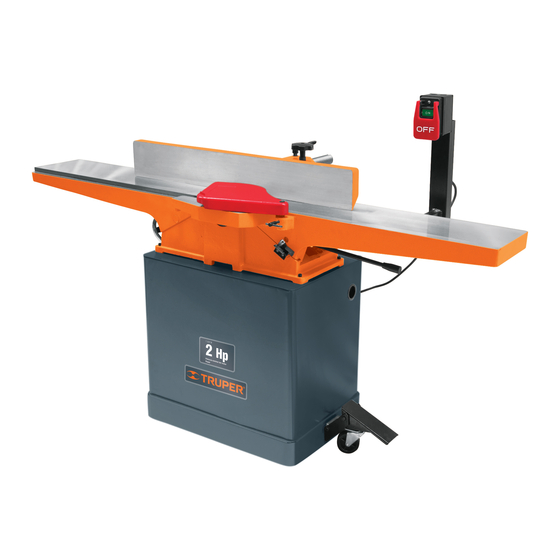
Jointer 8”
Hide thumbs
1
Table Of Contents
2
3
4
5
6
7
8
9
10
11
12
13
14
15
16
17
18
19
20
21
22
23
24
25
26
27
28
29
30
31
32
33
34
35
36
37
38
39
40
page
of
40
Go
/
40
Contents
Table of Contents
Bookmarks
Table of Contents
Table of Contents
Technical Data
Power Requirements
General Power Tool Safety Warnings
Safety Warnings for Jointers
Part List
Assembly
Parts
Adjustment
Adjusting the Fence
Start up
Work Piece
Operation
Maintenance
Notes
Authorized Service Centers
Warranty Policy
Advertisement
Quick Links
Download this manual
Manual
20 cm
Jointer 8"
Applies for:
Code
Model
16288
CANT-8X
CANT-8X
CAUTION
Read this manual thoroughly
before using the tool.
1 119 W
1 1/2 Hp
Table of
Contents
Previous
Page
Next
Page
1
2
3
4
5
Advertisement
Table of Contents
Need help?
Do you have a question about the CANT-8X and is the answer not in the manual?
Ask a question
Questions and answers
Related Manuals for Truper CANT-8X
Power Tool Truper CALA-A3 Manual
(24 pages)
Power Tool Truper PRO CALA-A3 Manual
Variable speed jig saw 0.7 hp power (24 pages)
Power Tool Truper CALA-A4 Manual
(24 pages)
Power Tool Truper CALA-NX6 Manual
1 hp power (24 pages)
Power Tool Truper CALA-NX6 Manual
Variable speed jig saw (24 pages)
Power Tool Truper PRO CALA-A5 Manual
Variable speed jig saw (24 pages)
Power Tool Truper CALA-A2 Manual
(24 pages)
Power Tool Truper CANT-6X Manual
6” jointer (41 pages)
Power Tool Truper CAU-50 Quick Start Manual
Soldering iron gun (3 pages)
Power Tool Truper CANT-6B Manual
Benchtop jointer (36 pages)
Power Tool Truper CALI-20A Manual
Cordless variable speed jig saw (28 pages)
Power Tool Truper CALA-NX6-2 Manual
1 hp power (24 pages)
Power Tool Truper HIDR-1/2X24 Manual
Hydropneumatic pressure boosting system (25 pages)
Power Tool Truper BAI-55 Manual
Tamping rammer (32 pages)
Power Tool Truper PRO LIMI-20A2 Manual
(33 pages)
Power Tool Truper MOTO-A2 Manual
0.2 hp power (24 pages)
This manual is also suitable for:
16288
Table of Contents
Print
Rename the bookmark
Delete bookmark?
Delete from my manuals?
Login
Sign In
OR
Sign in with Facebook
Sign in with Google
Upload manual
Upload from disk
Upload from URL


Need help?
Do you have a question about the CANT-8X and is the answer not in the manual?
Questions and answers