Table of Contents
Advertisement
Available languages
Available languages
Quick Links
tage I sta ati
Asse b y a d perati g i structi
tice d'e p i d'i sta ati
tage e bedie i gsha d eidi g
tage
ch ha teri gsa vis i g
Istru i
i di
taggi e fu
I strucci
es de
取扱説明書
s u d Bedie u gsa eitu g
s
et de
i
a e t
ta e y fu ci
a e t
Drehzahlregler
Speed control
Régulateur
de vitesse de rotation
Toerenregelaar
Varvtalsreglering
Regolatore di giri
Regulador de velocidad
回転数コントローラ
3120 200
tage
Advertisement
Chapters
Table of Contents

Subscribe to Our Youtube Channel
Related Manuals for Rittal SK 3120.200


Summary of Contents for Rittal SK 3120.200
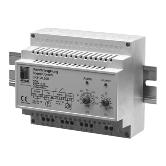
- Page 1 Drehzahlregler Speed control Régulateur de vitesse de rotation Toerenregelaar Varvtalsreglering Regolatore di giri Regulador de velocidad 回転数コントローラ 3120 200 tage I sta ati s u d Bedie u gsa eitu g Asse b y a d perati g i structi tice d’e p i d’i sta ati et de tage...
-
Page 3: Table Of Contents
Schaltschrank gekühlt wird (kalte Zuluft Tragschiene (EN 50 022) aufgerastet vorausgesetzt). Damit ergibt sich auch ein werden. reduzierter Energiebedarf. Der Drehzahl- regler ist besonders für die Rittal Filterlüf- ter und Luft/Luft-Wärmetauscher geeignet. 4 Funktionsbeschreibung 2 Sicherheitshinweise 4.1 Drehzahlregelung (P1) Die Schaltschranktemperatur wird auf die –... -
Page 4: Minimaldrehzahl (P2)
Bei einer gemessenen Temperatur von mehr als 10 K über dem eingestellten Soll- wert spricht die Temperaturüberwachung an, siehe Diagramm, Seite 5. Die rote LED blinkt 1x. Das Störmelderelais fällt ab (Klemmen 5-4 geschlossen). Montage-, Installations- und Bedienungsanleitung Rittal Drehzahlregler... -
Page 5: Anschluss
Abb. 3: Montage mit gekürtem Fühler Drehzahl 100 % Minimaldrehzahl Alarmrelais verschiebt Punkt A 5-4 offen auf dieser Linie Lüfter Drehzahl Alarmrelais Minimal- drehzahl geschlossen Temperatur Sollwert Sollwert Sollwert -10 K +10 K Abb. 4: Temperaturregelung Montage-, Installations- und Bedienungsanleitung Rittal Drehzahlregler... -
Page 6: Technische Daten
Garantie bei fachgerechter Anwendung Drehzahlregler vom Tage der Lieferung an. Bei unsachgemäßer Anwendung oder Fernfühler Anschluss erlischt die Gewährleistung Montageanleitung des Herstellers. Für die in solchem Fall Tab. 2: Lieferumfang entstandenen Schäden wird nicht gehaftet. Montage-, Installations- und Bedienungsanleitung Rittal Drehzahlregler... -
Page 7: Application
4.1 Speed control (P1) ..7 it is vital to read the Rittal assembly 4.2 Minimum speed (P2) ..8 instructions (plant documentation) 4.3 Monitoring/malfunctions . -
Page 8: Minimum Speed (P2)
At a measured temperature of more than 10K above the set value, temperature monitoring will cut in – see diagram, page 9. The red LED will flash once. The fault signal relay will drop out (terminal 5-4 closed). Rittal Speed control assembly and operating instructions... -
Page 9: Connection
100 % Alarm relay Minimum speed 5-4 open displaces point A along this line Fan speed Minimum Alarm relay speed 5-4 closed Temperature Setpoint Setpoint Setpoint -10 K +10 K Fig. 4: Temperature control Rittal Speed control assembly and operating instructions... -
Page 10: Technical Specifications
In the case of incorrect use or connection, Remote sensor the guarantee of the manufacturer ex- Set of assembly instructions pires. No liability is accepted for damage Tab. 2: Supply includes arising in such cases. Rittal Speed control assembly and operating instructions... -
Page 11: Consignes De Sécurité
L’appareil s’enclenche tout simplement sur le rail porteur de 35 mm (EN 50 022). 2 Consignes de sécurité – L’appareil est exclusivement prévu pour être installé dans une armoire électrique fermée Notice de montage, d’installation et d’emploi régulateur de vitesse de rotation Rittal... -
Page 12: Description Fonctionnelle
Régler P2 sur la vitesse de rotation Eviter de poser le câble parallèlement à la minimale désirée ligne d’alimentation. Vous pouvez à présent régler P1 sur la valeur de température désirée. Notice de montage, d’installation et d’emploi régulateur de vitesse de rotation Rittal... - Page 13 Vitesse de ventilateur d’alarme rotation 5-4 fermé minimale Température Valeur de consigne Valeur de consigne Valeur de consigne -10 K +10 K Fig. 4 : Régulation de la température Notice de montage, d’installation et d’emploi régulateur de vitesse de rotation Rittal...
-
Page 14: Caractéristiques Techniques
Capteur à distance Rittal décline toute responsabilité pour les Notice de montage dommages résultant d’une utilisation non conforme. Tab. 2 : Composition de la livraison Notice de montage, d’installation et d’emploi régulateur de vitesse de rotation Rittal... -
Page 15: Toepassing
(gekoelde inlaatlucht vereist). Hierdoor wordt bovendien de energiebehoefte lager. De toerentalrege- 3 Montage ling is bijzonder geschikt voor Rittal venti- De toerentalregeling kan eenvoudig op de latoren en lucht/lucht-warmtewisselaars. 35 mm montagerail (EN 50 022) worden bevestigd. -
Page 16: Minimaldrehzahl (P2)
Bij minimaal toerental = 100 % 50 m worden verlengd. Inkorten is moge- draait de ventilator altijd op lijk. Het geleiden van de kabel parallel aan maximale snelheid (geen voedingskabels dient te worden voorko- regeling). men. Montage-, installatie- en bedieningshandleiding Rittal Toerentalregeling... -
Page 17: Aansluiting
100 % Minimaal toerental Alarmrelais verschuift punt A 5-4 open langs deze lijn Ventilator- toerental Minimaal Alarmrelais toerental 5-4 gesloten Temperatuur Gewenste waarde Gewenste waarde Gewenste waarde -10 K +10 K Afb. 4: Temperatuurregeling Montage-, installatie- en bedieningshandleiding Rittal Toerentalregeling... -
Page 18: Technische Gegevens
Bij ondes- kundig gebruik of onjuiste aansluiting komt Remote sensor de garantieregeling van de fabrikant te Montagehandleiding vervallen. Tab. 2: Levering Voor hieruit voortkomende schade kan Rittal niet aansprakelijk worden gesteld. Montage-, installatie- en bedieningshandleiding Rittal Toerentalregeling... -
Page 19: Användning
4.2 Lägsta varvtal (P2) de apparatskåpsinstallation När det lägsta varvtalet uppnåtts stängs – Arbeten får enbart utföras av auktorise- fläkten av. Inställningarna anges i % i för- rad fackpersonal hållande till det maximala varvtalet. Det Montage-, installations- och manövreringsanvisning Rittal varvtalsreglering... -
Page 20: Övervakning/Störningar
Larmreläet slår ifrån (kontakterna 5-4 är slutna). Sensorfe/kortslutning: I förekommande fall körs fläkten med fullt varvtal. Den röda LED-n blinkar 3x. Larmreläet slår ifrån (kontakterna 5-4 är slutna). Spänningsbortfall (regulator utan spänning): Larmreläet slår ifrån (kontakterna 5-4 är slutna). Montage-, installations- och manövreringsanvisning Rittal varvtalsreglering... -
Page 21: Anslutning
Montage med avkortad sensor Varvtal 100 % Alarmrelä Lägsta varvtalet 5-4 öppen förskjuter punkt A på denna linje Fläktvarvtal Alarmrelä Lägsta 5-4 sluten varvtal Temperatur Börvärde Börvärde Börvärde -10 K +10 K Bild 4 Temperaturreglering Montage-, installations- och manövreringsanvisning Rittal varvtalsreglering... -
Page 22: Teknisk Information
Vid inkorrekt an- vändning eller felaktig anslutning upphör Temperaturgivare tillverkarens garantiansvar att gälla. Montageanvisning Rittal ansvarar inte för skador som upp- Tab. 2: Leveransinnehåll stått till följd av felaktig användng eller an slutning. Montage-, installations- och manövreringsanvisning Rittal varvtalsreglering... -
Page 23: Applicazione
– Il grado di protezione si raggiunge solo set impostato con il potenzio metro P1 se il montaggio è eseguito a regola (a condizione che l’aria in ingresso sia d’arte Istruzioni di montaggio e funzionamento Regolatore di velocità Rittal... -
Page 24: Numero Di Giri Minimo (P2)
Ora è possibile regolare P1 sulla tempera- tura desiderata. Con un numero di giri = 100 %, il ventilatore funziona sempre alla velocità massima (nessuna regolazione). Istruzioni di montaggio e funzionamento Regolatore di velocità Rittal... -
Page 25: Connessioni Elettriche
Relè Numero allarme di giri 5-4 chiusi minimo Temperatura Valore di set impostato Valore di set impostato Valore di set impostato -10 K +10 K Fig. 4: Regolazione della temperatura Istruzioni di montaggio e funzionamento Regolatore di velocità Rittal... -
Page 26: Dati Tecnici
Regolatore del numero di giri del costruttore decade. In tal caso Rittal Sonda remota non risponde di eventuali danni. Istruzioni di montaggio Tab. 2: Parti incluse nella fornitura Istruzioni di montaggio e funzionamento Regolatore di velocità Rittal... -
Page 27: Aplicación
– Tener en cuenta las medidas de seguri- entrada sea frío). La temperatura se mide dad según EN 60 335 durante el monta- a través del sensor remoto. Al alcanzar el je del aparato Instrucciones de montaje y servicio del control de velocidad Rittal... -
Page 28: Velocidad Mínima (P2)
Debe evitarse el guiado en paralelo Con velocidad mínima = 100 % excesivamente junto con cables de red. el ventilador funciona siempre a la velocidad máxima (sin regu- lación). Instrucciones de montaje y servicio del control de velocidad Rittal... -
Page 29: Conexión
5-4 abierto esta línea Velocidad ventilador Relé de alarma Velocidad 5-4 cerrado mínima Temperatura Valor teórico Valor teórico Valor teórico -10 K +10 K Imagen 4: Regulación de la temperatura Instrucciones de montaje y servicio del control de velocidad Rittal... -
Page 30: Datos Técnicos
Sensor remoto El fabricante no se hace responsable de Instrucciones de montaje los daños producidos a consecuencia de un uso y mantenimiento inadecuados del Tab. 2: Unidad de envase aparato. Instrucciones de montaje y servicio del control de velocidad Rittal... -
Page 31: 安全に関するご注意
1 用途 目次 ‒ 取扱説明書を遵守してください。 ‒ エンクロージャーの取付けにおける安全 1 用途 . . . . . . . . . . . . . . . . . . . . . . . . . 31 に関する注意事項を遵守してください。 2 安全に関するご注意 . . . . . . . . . . 31 ‒ 作業は必ず専門の作業員にお任せくださ い。 3 取付け . . . . . . . . . . . . . . . . . . . . . . . 31 ‒ エンクロージャーのまたはエンクロー 4 機能の説明. . . . . . . . . . . . . . . . . . . 31 ジャー内の変更をする場合(例えば、他 4.1 回転数制御 . . . . . . . . . . . . . . . . . . . 31 の設置場所または新しい機器の取付け) 4.2 最低回転数 . . . . . . . . . . . . . . . . . . . 32 は必ずリタールの取扱説明書を事前に読 4.3 監視/障害 . . . . . . . . . . . . . . . . . . . 32 み、それに従ってください。... -
Page 32: 最低回転数
4 機能の説明 ファンがオンになるときは、パルス信号に より起動します。 緑 = 電源がオン 赤 = 障害あり、 「4.3 監視/障害」 項を 4.2 最低回転数(P2) 参照 最低回転数に達すると、ファンはオフにな 4.5 リモートセンサー ります。 設定は最大回転数に対する、パー センテージで行います。ファンが最低回転 リモートセンサーは 230 V 用 2 心ケーブル 数でもまだ回転していることを確認する必 を使って約 50 m まで伸ばすことができま 要があります(メーカーの取扱説明書を参 すが、短くすることも可能です。電源ケー 照) 。 ブルと平行に敷くのは避けてください。 当社 3321.xxx – 3327.xxx シリーズのフィ ルターファンでは、最低回転数は... - Page 33 5 接続 5 接続 Power Alarm Sensor Imax. = 5A 100-230V AC Imax. 2A 図 1: 電気接続図 図 2: センサーの寸法 図 3: 短くしたセンサーの取付け 回転数 100 % 最低回転数を変え アラームリ ると、A 点がこの レー 5-4 開 線上で移動しま す。 ファン回転数 アラームリ 最低回転数 レー 5-4 閉 温度 目標値...
-
Page 34: 同梱品
6 仕様 6 仕様 3120.200 品番 100 〜 230 V AC, (-15, +10 %), 50/60 Hz 電圧 設定温度範囲 (P1) 20 〜 55°C, 68 〜 131°F 最低回転数 (P2) 設定範囲 ~0 〜 100 % 最低回転数 〜 100 % ファン回転数 長さ 1.80 m 温度センサー... - Page 36 Enclosures Power Distribution Climate Control IT Infrastructure Software & Services RITTAL GmbH & Co. KG Postfach 1662 · D-35726 Herborn Phone +49(0)2772 505-0 · Fax +49(0)2772 505-2319 E-mail: info@rittal.de · www.rittal.com...
Need help?
Do you have a question about the SK 3120.200 and is the answer not in the manual?
Questions and answers