
Related Manuals for Axis A1210


Summary of Contents for Axis A1210
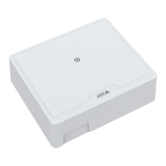
- Page 1 AXIS A1210 Network Door Controller AXIS A1210-B Network Door Controller User manual...
-
Page 2: Table Of Contents
Check the current AXIS OS version ........ -
Page 3: Solution Overview
Solution overview Solution overview The network door controller can easily be connected to and powered by your existing IP network with no need for special cabling. - Page 4 Solution overview Each network door controller is an intelligent device that is easily mounted close to a door. It can power and control up to two readers.
-
Page 5: Installation
Installation Installation To watch this video, go to the web version of this document. help.axis.com/?&piaId=74266§ion=solution-overview... -
Page 6: Get Started
Get started Find the device on the network To find Axis devices on the network and assign them IP addresses in Windows®, use AXIS IP Utility or AXIS Device Manager. Both applications are free and can be downloaded from axis.com/support. -
Page 7: Secure Passwords
Verify that no one has tampered with the device software To make sure that the device has its original AXIS OS, or to take full control of the device after a security attack: 1. Reset to factory default settings. See . -
Page 8: Configure Your Device
Configure your device Configure your device For how to configure your device, see AXIS Camera Station user manual or third-party solutions. -
Page 9: The Web Interface
Device info Shows the device information, including AXIS OS version and serial number. Upgrade AXIS OS: Upgrade the software on your device. Takes you to the Maintenance page where you can do the upgrade. Time sync status Shows NTP synchronization information, including if the device is in sync with an NTP server and the time remaining until the next sync. -
Page 10: Device
Apps Add app: Install a new app.Find more apps: Find more apps to install. You will be taken to an overview page of Axis apps.Allow unsigned apps : Turn on to allow installation of unsigned apps.Allow root-privileged apps : Turn on to allow apps with root privileges full access to the device. -
Page 11: System
The web interface • Deactivate the license: Deactivate the license to replace it with another license, for example, when you change from a trial license to a full license. If you deactivate the license, you also remove it from the device. •... - Page 12 The web interface Network IPv4 Assign IPv4 automatically: Select to let the network router assign an IP address to the device automatically. We recommend automatic IP (DHCP) for most networks.IP address: Enter a unique IP address for the device. Static IP addresses can be assigned at random within isolated networks, provided that each address is unique.
- Page 13 Authentication failed: Sends a trap message when an authentication attempt fails. Note All Axis Video MIB traps are enabled when you turn on SNMP v1 and v2c traps. For more information, see AXIS OS Portal > SNMP. • v3: SNMP v3 is a more secure version, which provides encryption and secure passwords. To use SNMP v3, we...
- Page 14 Axis' implementation, the device and the authentication server authenticate themselves with digital certificates using EAP-TLS (Extensible Authentication Protocol - Transport Layer Security).To allow the device to access a network protected through certificates, you must install a signed client certificate on the device.Authentication method: Select an EAP type used for...
- Page 15 Confirm rules: Click to activate the pending rules.Active rules: An overview of the rules you are currently running on the device. : Click to delete an active rule. : Click to delete all rules, both pending and active. Custom signed AXIS OS certificate...
- Page 16 To install test software or other custom software from Axis on the device, you need a custom signed AXIS OS certificate. The certificate verifies that the software is approved by both the device owner and Axis. The software can only run on a specific device which is identified by its unique serial number and chip ID.
- Page 17 IoT integration and is used in a wide variety of industries to connect remote devices with a small code footprint and minimal network bandwidth. The MQTT client in Axis device software can simplify integration of data and events produced in the device to systems which are not video management software (VMS).Set up the device as an MQTT client.
- Page 18 The web interface Use default topic prefix: Select to use the default topic prefix, that is defined in the device topic prefix in the MQTT client tab.Include topic name: Select to include the topic that describes the condition in the MQTT topic.Include topic namespaces: Select to include ONVIF topic namespaces in the MQTT topic.Include serial number: Select to include the device’s serial number in the MQTT payload.
-
Page 19: Maintenance
Server: Click to add a new server.Host: Enter the hostname or IP address of the server.Format: Select which syslog message format to use. • Axis • RFC 3164 • RFC 5424 Protocol: Select the protocol to use: •... - Page 20 AXIS OS upgrade: Upgrade to a new AXIS OS version. New releases can contain improved functionality, bug fixes, and completely new features. We recommend you to always use the latest AXIS OS release. To download the latest release, go to axis.com/support.
-
Page 21: Learn More
Signed OS Signed OS is implemented by the software vendor signing the AXIS OS image with a private key. When the signature is attached to the operating system, the device will validate the software before installing it. If the device detects that the integrity of the software is compromised, the AXIS OS upgrade will be rejected. -
Page 22: Specifications
Specifications Specifications Product overview Network connector Grounding position Relay jumper Power connector Relay connector Door connector Reader connector Auxiliary connector External connectors 10 Control button LED indicators Color Indication Status Green Steady green for normal operation. Amber Steady during startup and when restoring settings. Slow flash for failed upgrade. -
Page 23: Buttons
UL: Power over Ethernet (PoE) shall be over Ethernet IEEE 802.3af/802.3at Type 1 Class 3 or Power over Ethernet Plus (PoE+) IEEE 802.3at Type 2 Class 4 power limited injector that provides 44–57 V DC, 15.4 W / 30 W. Power over Ethernet (PoE) has been evaluated by UL with AXIS T8133 Midspan 30 W 1-port. Power priority This device can be powered by either PoE or DC input. - Page 24 Important • When the reader is powered by the controller, the qualified cable length is up to 200 m (656 ft). Verified only for Axis readers. • When the reader is not powered by the controller, the qualified cable length for reader data is up to 1000 m (3280,8 ft) if the following cable requirements are met: 1 twisted pair with shield, AWG 24, 120 ohm impedance.
- Page 25 Specifications Door connector One 4-pin terminal block for door monitoring devices (digital input). Door monitor supports supervision with end of line resistors. If the connection is interrupted, an alarm is triggered. To use supervised inputs, install end of line resistors. Use the connection diagram for supervised inputs. See . Function Notes Specifications...
-
Page 26: Auxiliary Connector
Specifications Power source Max power at 12 V DC Max power at 24 V DC DC IN 1 600 mA 800 mA 900 mA 450 mA NOTICE TICE TICE If the lock is non-polarized, we recommend you to add an external flyback diode. Auxiliary connector Use the auxiliary connector with external devices in combination with, for example, motion detection, event triggering, and alarm notifications. -
Page 27: External Connector
Specifications DC ground DC output 12 V I/O configured as input I/O configured as output External connector Two 2-pin terminal blocks for external devices, for example glass break or fire detectors. UL: The connector has not been evaluated by UL for burglar or fire alarm use. Function Notes Specifications... -
Page 28: Supervised Inputs
Specifications Function Notes Specifications 0 V DC DC ground (GND) For powering the device when DC input 12 V DC, max 36 W not using Power over Ethernet. Note: This pin can only be used as power in. UL: DC power to be supplied by a UL 603 listed power supply, depending on application, with appropriate ratings. Supervised inputs To use supervised inputs, install end of line resistors according to the diagram below. -
Page 29: Troubleshooting
Using AXIS OS from the active track is recommended if you want to access the newest features, or if you use Axis end-to-end system offerings. The LTS tracks are recommended if you use third-party integrations, which are not continuously validated against the latest active track. -
Page 30: Technical Issues, Clues, And Solutions
Note When you upgrade the device with the latest AXIS OS version in the active track, the product receives the latest functionality available. Always read the upgrade instructions and release notes available with each new release before you upgrade. To find the latest AXIS OS version and the release notes, go to axis.com/support/device-software. -
Page 31: Contact Support
IP addresses obtained from a DHCP server are dynamic and may change. If the IP address has been changed by DHCP changed, use AXIS IP Utility or AXIS Device Manager to locate the device on the network. Identify the device using its model or serial number, or by the DNS name (if the name has been configured).If required, a static IP address can be assigned manually. - Page 32 User manual Ver. M7.3 Date: October 2024 © Axis Communications AB, 2022 - 2024 Part no. T10181041...
Need help?
Do you have a question about the A1210 and is the answer not in the manual?
Questions and answers