
Related Manuals for Oerlikon OPTIPULS 350 I


Summary of Contents for Oerlikon OPTIPULS 350 I
- Page 1 OPTIPULS 350 I BETRIEBS- WARTUNGS- UND SICHERHEITSANLEITUNG SAFETY INSTRUCTION FOR USE AND MAINTENANCE OPTIPULS 350 I SA8695-0881 AUSG. : D/GB Betriebsanleitung REVISION : O Instructions for use DATUM : 04-2005...
- Page 2 Le soudage à l'arc et le coupage plasma peuvent être dangereux pour l'opérateur et les personnes se trouvant à proximité de l'aire de travail. Lire le manuel d'utilisation. Arc welding and plasma cutting may be dangerous for the operator and persons close to the work area.
-
Page 4: Table Of Contents
INHALTSVERZEICHNIS CONTENTS SICHERHEITSHINWEISE ..................................3 SAFETY INSTRUCTIONS..................................3 1. ELEKTRISCHE SICHERHEITSMASSNAHMEN ..........................4 (ANSCHLUSS, WARTUNG, INSTANDSETZUNG) ..........................4 1. ELECTRIC SAFETY (DECREE 88-1056 DATED NOVEMBER 14 1988)..................4 (CONNECTION, MAINTENANCE, TROUBLESHOOTING) ........................4 2. GEFAHREN INNERER VERLETZUNGEN............................6 2. PROTECTION FROM SMOKE, VAPORS, HARMFUL AND TOXIC GASES..................6 3. - Page 5 6. ERWEITERTE KONFIGURATION DER ANLAGE..........................22 6. POWER SOURCE ADVANCED CONFIGURATION........................22 SET-UP (EASY) ....................................22 7. SPEZIELLE KONFIGURATION DER STROMQUELLE VERSTECKTES SET UP (EXPERT)............24 7. POWER SOURCE VERY ADVANCED CONFIGURATION HIDDEN SET UP (EXPERT) ...............24 8. ZUSÄTZLICHE INFORMATIONEN..............................27 8. FURTHER INFORMATIONS................................27 D - WARTUNG ......................................28 D - MAINTENANCE ....................................28 1.
-
Page 7: Sicherheitshinweise
Labor Regulations. Abschließend möchten wir Sie bitten, OERLIKON über etwaige OERLIKON would ask you to advise it of any anomaly that you may Unregelmäßigkeiten zu informieren, die Ihnen bei der Lektüre note in the preparation of this notice. -
Page 8: Elektrische Sicherheitsmassnahmen
ACHTUNG : Der Schweiß-/Schneidgenerator darf nur CAUTION: a welding/cutting power-source must be zu dem Zweck verwendet werden, zu dem er used only for the function for which it is intended. In konstruiert wurde. Er darf insbesondere keinesfalls no case may it be used, especially to recharge zum Laden von Batterien, Enteisen von batteries, unfreeze water pipes, heat premises Wasserleitungen, Heizen von Räumen unter Einsatz... - Page 9 An diesem Modul dürfen Sie keine You must never work or perform servicing operations on this Arbeiten durchführen (wenden Sie sich gegebenenfalls an die circuit (contact OERLIKON for all servicing operations). Firma OERLIKON). Prüfen Sie spätestens alle 6 Monate den Zustand der Isolierung At least every six months, you must check the proper condition of und die Anschlüsse der elektrischen Bauteile wie Stecker,...
-
Page 10: Gefahren Innerer Verletzungen
Nationalen Institut für Forschung und Sicherheit (INRS), der methods and various practical application examples. Berechnungsmethoden und verschiedene praktische Anwendungsbeispiele enthält. OERLIKON bietet verschiedene Absaugsysteme an, die auf Ihre OERLIKON proposes an entire range of suction systems Bedürfnisse zugeschnitten sind. corresponding to your needs. -
Page 11: Lärmschutz
Ohrenstöpseln, Arbeiten in einer schallgehemmten Zone und appropriate signaling means. Information durch entsprechende Kennzeichnung. OERLIKON bietet verschiedene Schutzausrüstungen an, die auf OERLIKON proposes an entire range of protective equipment Ihre Bedürfnisse zugeschnitten sind. corresponding to your requirements. OPTIPULS 350... -
Page 12: Brandschutz
5. BRANDSCHUTZ 5. PROTECTION FROM FIRE Entfernen Sie alle entflammbaren Gegenstände aus der Funkenzone Remove inflammable products and equipment from the area where des Lichtbogens oder schützen Sie diese. arc spatter may occur, or protect them. Schweißen bzw. Schneiden Sie nicht in der Nähe einer Luft- oder Do not weld or cut near a ventilation pipe, gas pipe or other Gaszufuhr bzw. - Page 13 ! Verwendung der Geräte ! Use of the equipment ! Verwenden Sie ausschließlich für das jeweilige ! use only equipment which is designed for the Gas vorgesehene Geräte ; gas used; ! Stellen Sie sicher, dass Flasche und ! check that the cylinder and the pressure- Druckminderventil für das verwendete Gas reducing valve correspond to the gas necessary vorgesehen sind ;...
-
Page 14: Körperschutz
b) Zusätzliche Hinweise für bestimmte Gase b) Additional recommendations for certain gases b.1) Gase und Mischgase, die weniger als 20 % CO2 b.1) Gas and gaseous mixtures containing less than 20 % enthalten Wenn diese Gase oder Mischgase den Sauerstoff der Luft If these gases or mixtures take the place of the oxygen in verdrängen, besteht Erstickungsgefahr. -
Page 15: A - Allgemeines
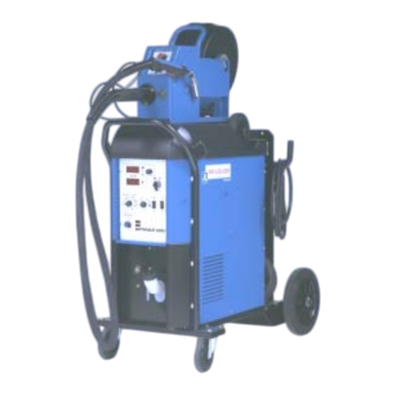
A - GENERAL INFORMATION 1. PRÄSENTATION DER ANLAGE 1. PRESENTATION OF INSTALLATION ist eine Wassergekühlte Anlage, die zum OPTIPULS 350 i is a water cooled welding set enabling OPTIPULS 350 i MIG-MAG-Schweißen im Glattstrom- bzw. Pulsstromverfahren one to work in smooth current or pulsed current MIG-MAG. The ausgelegt wurde. -
Page 16: Anlagenaufbau
2. ANLAGENAUFBAU 2. WELDING SET CONSTITUENT Die Standard-Ausführungen mit dem 2m- (Art.-Nr SA 9160 1424), The standard welding-sets with 2m long (ref. SA 9160 1424), 5m 5m- (Art.-Nr SA 9160 1425) oder 10m-lang Zwischenschlauchpaket long(ref. 91601425) or 10m long (ref. SA 9160 1426) harness are (Art.-Nr SA 9160 1426) wird betriebsbereit geliefert und mit den delivered ready to use and are comprised of : folgendem ausgestattet :... -
Page 17: Beschreibung Der Bedienelemente
3. BESCHREIBUNG DER BEDIENELEMENTE 3. FRONT PANEL AND WIRE FEEDER DESCRIPTION Anzeige Schweißstrom / Welding current/Wire speed/Plate thickness Drahtgeschwindigkeit / Blechdicke display-unit Umschalter für Anzeige Schweißstrom / Welding current/Wire speed/Plate thickness Drahtgeschwindigkeit / Blechdicke switch Anzeige Schweißspannung Voltage display-unit Netzschalter Ein / Aus On/Off Umschalter MIG-MAG / PULS / Gas- Wire/Gaz and process selection (MMA, MIG... -
Page 18: Zubehör
Remote control, ref. 9160-1067 Schwenkfuss, ref. 9160-1064 Pivot support, ref. 9160-1064 OPTIBOX, ref. 9160-1068 OPTIBOX, ref. 9160-1068 5. TECHNISCHE DATEN STROMQUELLE 5. TECHNICAL SPECIFICATIONS POWER SOURCE OPTIPULS 350 i REF. SA 9160-1419 / 9160-1420 PRIMÄR E-Hand / MMA PRIMARY Primär-Versorgung 3~ 400V... -
Page 19: B - Inbetriebnahme
B - INBETRIEBNAHME B - STARTING UP 1. AUSPACKEN DER ANLAGE 1. UNPACKING THE SET ! Karton-Box vom Gerät abnehmen ! Remove the cardboard covering the welding unit ! Schweißstromquelle vom Holzsockel mit Hubseilen bzw. ! Lift the power source from the wooden base using slings or a einem Gabelstapler hochheben forklift truck Kranöse... -
Page 20: Netzanschluss
3. NETZANSCHLUSS 3. ELECTRICAL CONNECTIONS TO THE MAINS wird geliefert: is delivered: OPTIPULS 350 i OPTIPULS 350 i mit angeschlossenem Primärkabel with the primary cable connected to the power-source mit 400V 3-phasige Werkschaltung (CE Version) ! coupling 400V three-phases Zulässige Netzfrequenzen : 50 und 60 Hz... -
Page 21: C - Betriebsanweisung
C - BETRIEBSANWEISUNG C - INSTRUCTIONS FOR USE 1. AUSWAHL DES SCHWEISSDRAHTES 1. CHOOSE THE WIRE OPTIPULS 350i Die OPTIPULS 350i ermöglicht das MIG-MAG-Schweißen enables MIG welding with or without mit oder ohne Puls-Strom. pulsed current. Der verwendete Draht, der Durchmesser und sogar die Gassorte Wire type and diameter, as well as protection gas must be chosen in sind auf den zu schweißenden Werkstoff abzustimmen. -
Page 22: Einschalten Und Einstellarbeiten
2. EINSCHALTEN UND EINSTELLARBEITEN 2. STARTING UP AND ADJUSTMENT ! Einschalten : Der Hauptschalter EIN/AUS ! Starting up : the main ON/OFF switch is located befindet sich auf der Frontseite der Anlage. on the front panel of the power-source. This Zur Inbetriebnahme den Schalter auf Position switch is used to start the unit up on position stellen. -
Page 23: Bedienung Der Stromquelle Für Mig-Mag Schweissen
4. BEDIENUNG DER STROMQUELLE FÜR MIG-MAG 4. USE OF POWER SOURCE FOR MIG-MAG SCHWEISSEN WELDING Erdungskabel und Leistungskabel an die Earth conductor and harness must be connected to the Leistungsbuchsen der Anlage anschließen. power source. The polarity is chosen according to the wire Auswahl der Polarität abhängig von der Drahtsorte type (see page 19). - Page 24 Abstimmung auf die Gasart, den Draht und Drahtdurchmesser gas, wire type and diameter. The middle position of the button gives optimiert. Die Mittenposition des Knopfes entspricht der besten the best adjustment, corresponding to the general application of the Einstellung für eine allgemeine Anwendung der gewählten wire/gas used.
-
Page 25: Auswahl Der Schweisszyklen
5. AUSWAHL DER SCHWEISSZYKLEN 5. WELDING CYCLES SELECTION Im MIG-MAG-Betrieb hat das Drücken des Brennerschalters In MIG-MAG welding mode, pressing the trigger of the torch has verschiedene Auswirkungen – abhängig vom Zyklus oder dem different effects, depending on the cycle or welding method verwendeten Schweißbetrieb. -
Page 26: Erweiterte Konfiguration Der Anlage
6. ERWEITERTE KONFIGURATION DER ANLAGE 6. POWER SOURCE ADVANCED CONFIGURATION SET-UP (Easy) /Bestimmte Generator-Funktionsparameter sind sehr leicht Certain power source operating parameters can be easily einstellbar. Eine solche Konfiguration erfolgt durch Abrufen des configured. This configuration is carried out by accessing the SETUP-Programmes. - Page 27 Um zur nächsten Meldung zu gehen, muss der Taster Press the wire feed button to access to the next am Drahtvorschubgerät gedrückt werden. parameter. Strom Hot Start Hot Start Intensity Werkseinstellung 0V Plant setting 0V Zwischen –70% and +70% in Stufen von 1% einstellbar Possible values from –70% to +70% in steps of 1% Diese Einstellung optimiert das Zünden des Lichtbogens.
-
Page 28: Spezielle Konfiguration Der Stromquelle Verstecktes Set Up (Expert)
Um zur nächsten Meldung zu gehen, muss der Taster Press the wire feed button to access to the next am Drahtvorschubgerät gedrückt werden. parameter. Einstellung von Lichtbogen-Dynamik im Adjustment of melting dynamism in Short Arc. Kurzlichtbogen-Betrieb Werkseinstellung Sof Plant setting Sof oder/or Mögliche Einstellung: har (hard, harte Lichtbogen) - Page 29 1. Frontwand abschrauben 1. Unscrew the front panel 2. Dip-Switch 3 auf dem Print auf Position ON (Zugang EXPERT 2. Select ON position for the switch 3 (access to the EXPERT SETUP erlaubt) schalten SETUP allowed). 3. Frontseite wieder festschrauben 3.
- Page 30 Einstellung Kraterfüller Crater-filling adjustment Werkseinstellung 30% Plant setting 30% Zwischen 0 und 100% in Stufen von 1% einstellbar. Possible values from 0 to 100% in steps of 1%. Achtung: Wenn die Kraterfüller Zeit Null beträgt, ist der Note: if the crater-filling time is zero, there will be no Kraterfüller außer Funktion.
-
Page 31: Zusätzliche Informationen
8. ZUSÄTZLICHE INFORMATIONEN 8. FURTHER INFORMATIONS Drahtvorschub Taster Wire feed button Der Drahtvorschub-Taster hat zwei verschiedene Funktionen: The wire feed button has 2 different functions : Die Entlüftungsfunktion der Gasleitung wird durch einen The gaz purge fonction is accessible through a short action on kurzen Druck (weniger als 1 Sek.) auf den Taster ausgelöst. -
Page 32: D - Wartung
D - WARTUNG D - MAINTENANCE 1. ERSATZTEILE 1. SPARE PARTS Pos. Artikel-Nr Bezeichnung Description Item Ref. Gehäuse External items SA 9160 8470 Fahrwagen* Handle SA 9160 8460 Kunststoffabdeckung Plastic cover SA 9160 8453 Rechte Seitenwand* Right panel SA 9160 8455 Linke Seitenwand* Left panel ∅... - Page 33 D - 29 OPTIPULS 350...
-
Page 34: Fehlersuche
2. FEHLERSUCHE 2. DIAGNOSIS CHART Eingriffe auf den E-Anlagen dürfen nur durch qualifiziertes Servicing operations carried out on electric installations must Fachpersonal vorgenommen werden (Siehe Kap. be performed by persons qualified to do this kind of work (see SICHERHEITSBESTIMMUNGEN) SAFETY RECOMMANDATIONS section) URSACHEN ABHILFE CAUSES... - Page 35 BRENNERSCHALTER GEDRÜCKT / KEINE TRIGGER PRESSED / NO ERROR MESSAGE ON DISPLAY – FEHLERMELDUNG AM DISPLAY / UNIT / THE WIRE FEED MOTOR DOESN’T WORK / NO NO- DRAHTVORSCHUBMOTOR LÄUFT NICHT / KEINE LOAD VOLTAGE / THE PRE-DISPLAY WORKS LEERLAUFSPANNUNG / VORANZEIGE FUNKTIONIERT * Stecker defekt ! Stecker J1, J2 und B9, B6 * Connectors defective...
-
Page 36: Schaltbild
SCHALTBILD ELECTRICAL DIAGRAM D - 32 OPTIPULS 350... - Page 37 GRE USERWACHUNG IB AUSWAHL GRE USERWACHUNG RAC1 GRE STEUERUNG GRE STEUERUNG Drossel FRONTSEITE UNTER-EINHEIT ECH1 F 9160 8506 FRONTSEITE PLATINE F 9160 8505 OPTIPULS 350 I/380 IW RESV1 GAS TEST SCHWARZ SCHALTER INDICE DATE MOTIF 12x0.75mm2 SCHALTER BLAU DRAHTVORSCHUB 22/02/05 Suppression contrôleur débit...
- Page 38 OPTIPULS 350 I OEE 8695 0881 D/GB MODIFICATIONS APPORTEES Première page : Changement de l'indice de révision en O Page : 14 Dans l'encart ATTENTION, suppression de "CALOPORTEUR 285, 9257 9773 " remplacé par REF. SA "FREEZCOOL ". REF. SA 9000 0657 Dernière page :...
Need help?
Do you have a question about the OPTIPULS 350 I and is the answer not in the manual?
Questions and answers