Table of Contents
Advertisement
Quick Links
Advertisement
Table of Contents

Related Manuals for Walter SURFOX 306


Summary of Contents for Walter SURFOX 306
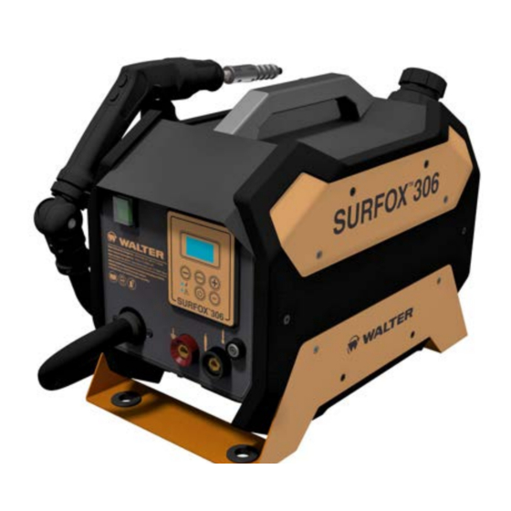
- Page 1 SURFOX 306 USER MANUAL SURFOX website...
-
Page 3: Table Of Contents
TABLE OF CONTENTS 1. Safety ................................5 1.1. Personal protective equipment (PPE) .....................6 1.2. Protection systems built into the device ....................8 1.3. Residual risks............................8 1.4. First aid measures ..........................8 2. Device characteristics ..........................9 2.1. Fields of application ..........................9 2.2. Basics of passivation ..........................9 2.3. - Page 4 8. Marking/Etching .........................41 (optional) 8.1. Overview of marking/etching wand accessories ...................41 8.2. Marking insert installation ........................42 8.3. Mounting a pad on the marking insert....................42 8.4. Electrical installation ..........................43 8.5. Start of processing ..........................44 8.6. After processing ............................45 8.7. Shutdown ..............................45 9.
-
Page 5: Safety
With proper care and maintenance, your unit will provide years of reliable service. WALTER (walter.com) is at your disposal to provide all the marketing and CUSTOMER ASSISTANCE DEPARTMENT user information. -
Page 6: Personal Protective Equipment (Ppe)
(otherwise any form of warranty will be voided) and must be implemented. do not mix these products with others. The SURFOX 306 is equipped with a built-in fume Always store these substances in a safe place in their abatement system: original containers, out of the reach of children and other unqualified persons. -
Page 7: Burn Prevention
All users of the device must wear suitable protective gloves URN PREVENTION During the cleaning process, the wand tip and work piece for the handling of the parts and for the use of the wand. can reach very high temperatures: •... -
Page 8: Protection Systems Built Into The Device
1.2. Protection systems built into the device HERMAL PROTECTION ROTECTION AGAINST SHORT CIRCUITS All SURFOX units automatically shut down if excessive All SURFOX units are equipped with a built-in short circuit overheating is detected on the inverter board. protection system that can occur between the insert installed When this protection system is activated, the device on the wand and the workpiece, in particular when the immediately shuts down and cannot be restarted until it has... -
Page 9: Device Characteristics
2.3. Transport and storage of the device To facilitate transport, the SURFOX 306 is equipped with a handle at the top. See chapter 14 for detailed information on the size and weight of the device. Make sure the switch is in the OFF position before connecting or moving the unit to avoid unintentional starting. -
Page 10: Device Components
2.4. Device components 1 Display 8 Alarm LED (red) 2 Voltage decrease button 9 Black socket for marking wand 3 MODE button 10 Black socket for DW wand 4 Voltage increase button 11 Red socket for ground cable 5 SET button 12 Main switch (ON/OFF) 6 Power button 13 Ground cable... - Page 11 14 Blowing Wand 21 Compressed air connector 15 Wand control buttons (START/STOP) 22 Serial number 16 Handle 23 Collecting tray 17 Tank cap 24 Wand holder 18 Pad mounting tool 19 Rating plate 20 Power cord...
-
Page 12: How To Install The Accessories
2.5. How to install the accessories Included hex keys (5 mm and 3 mm) 1. W AND HOLDER • Align the wand holder with the proper holes on the left side of the unit. • Use a 3 mm hex key (included) to tighten the two mounting screws. - Page 13 2. C OLLECTING TRAY • The collection tray consists of two parts: the bracket (A) and the tray (B). • First, use a 3 mm hex key (included) and two M5X8 screws to install the bracket into the corresponding holes on the left side of the unit.
-
Page 14: Control Panel
3. CONTROL PANEL 3.1. General description screen during processing PICKLING PICKLING PWR: HIGH PUMP: 1 1 Display 9 Power button 2 Operating mode indicator 10 SET button 3 Set voltage (V) 11 Power LED (green) 4 Pump program indicator 12 Alarm LED (red) 5 Device power indicator 13 Set voltage (V) 6 Voltage decrease button... -
Page 15: Menu Structure
"I"; this switch, colored green, is located in the front of the device (see chapter 2.4). During startup, the WALTER logo and a screen with the firmware information are briefly displayed on the screen. The unit then moves on to the PICKLING BRUSH program. -
Page 16: Power Adjustment
3.4. Power adjustment To change the power output of the device, press the SET button once and access the configuration screens (see diagram below). Use the – and + keys to choose from the available options. power HIGH << >> power <<... -
Page 17: Pump Adjustment
You can completely disable the pump by selecting the OFF program. << >> PUMP DYNAMIC mode is a new feature in the SURFOX 306. When dynamic adjustment is selected, the pump is automatically Speed controlled by the device electronic parts, which decide moment- <<... -
Page 18: Alarm Messages
To help the user identify the source of the problem more easily, the unit displays a text message indicating the probable cause of the malfunction. After solving the problem, press the MODE button to reset the device and resume work. For further assistance, contact WALTER Customer Service (walter.com). OVER HEATING The thermal protection system has been activated (see chapter 1.2). -
Page 19: Mounting Accessories On The Wand
4. MOUNTING ACCESSORIES ON THE WAND During the installation of inserts, pads and brushes, the device must be switched off: • Switch the main switch to the "O" position. • Disconnect the device from the mains. For its normal operation, the device requires the use of particular acid solutions that can be dangerous (read chapter 1 carefully). -
Page 20: Installation Of Brush Adaptor / Inserts
23 54-B 002 PTFE clamp ring for standard cleaning pads optional p. 23 WALTER C (walter.com) is available for any additional information. ustomer ervice 4.2. Installation of brush adaptor / inserts • Take the brush adaptor or the desired insert. -
Page 21: Mounting Brushes
4.3. Mounting brushes Included 10 mm wrench • Install the brush adaptor (A) on the wand (see chapter 4.2). • The adaptor is equipped with a threaded coupling (B) on which to screw the brush. • Screw the brush onto the threaded coupling; be careful when threading the end of the brush tube (C). -
Page 22: Mounting Pad On Graphite Insert 100 Mm
4.4. Mounting pad on graphite insert 100 mm • Install the insert on the wand (see chapter 4.2). 54-B 607 • Fold the pad into a "U" shape and slide it into the fins with grooves (A) on the electrode. 54-B 608 •... -
Page 23: Mounting Pads With Ptfe Clamp Ring
4.6. Mounting pads with PTFE clamp ring In some types of inserts (e.g. ), the pad is fixed using 54-B 143 a PTFE clamp ring (e.g. ). In these cases, the pad 54-B 002 mounting tool on the back of the device is used for assembly (refer to chapter 2.4). -
Page 24: Brush Bristle Length Adjustment
4.7. Brush bristle length adjustment • The SURFOX 306 brushes are made up of segments that must be gradually removed as the bristles wear out. 4 segments 54-B 606 3 segments 54-B 155 3 segments 54-B 601 • Once the bristles are worn down, use long nose pliers to remove the first segment (A). -
Page 25: Before Device Startup
5. BEFORE DEVICE STARTUP 5.1. Precautions for the use of the device To avoid damage to the device, check that: • The mains voltage corresponds to that supported by the unit (as specified in the technical data and rating plate). •... -
Page 26: Filling The Tank
5.2. Filling the tank • Make sure that the device is resting firmly on a flat, level surface. • Remove the tank cap (A). • Pour in about 1.8 l of electrolyte solution; the level of the liquid must never reach the brim. Acid solutions can be harmful to people and the environment, so during the tank refilling operations, take all the precautions described... -
Page 27: Electrical Installation
5.4. Electrical installation Make sure you have read and checked all the precautionary notes in chapter 5.1. • Prepare the wand by installing the most suitable accessory for the type of work you want to undertake (see chapter 4). • Connect the ground cable connector (A) to the red socket on the front panel of the unit. -
Page 28: Cleaning And Polishing Of Welds
• SURFOX-G, a pH neutral cleaning solution suitable for pickling only. Always refer to the product data sheet for detailed indications regarding its field of use. WALTER C (walter.com) is available for any additional information. ustomer ervice Acid solutions are dangerous and can cause damage to people and property: read the chapter 1 carefully for safety precautions and personal protective equipment to use when working with these substances. - Page 29 • Press and hold the STOP button on the wand switch to force pump activation and make sure that the pad or brush is properly moistened with the electrolyte solution before starting processing. If the electrode is not in contact with the surface to be treated (i.e. there is no current), the pump stops working regardless of the operating mode selected;...
- Page 30 • The polishing process requires a greater amount of electrolyte solution than pickling. • Always keep the brush/pad well moistened with the electrolyte solution to avoid overheating and a consequent significant reduction in its working life; if there are obvious signs of wear, replace the component immediately.
-
Page 31: After Processing
6.2. After processing • Press the STOP button on the wand switch (or alternatively button on the control panel) to stop the current supply to the wand and stop the fume abatement system. • Put the wand back in its holder (A). At the end of processing, always store the wand and other accessories appropriately. -
Page 32: Dw Wand
Brush adaptor optional p. 33 54-B 604 DW brush for S306 optional p. 35 54-B 605 DW sleeve optional p. 35 54-B 618 Brush extraction tool optional p. 35 WALTER C (walter.com) is available for any additional information. ustomer ervice... -
Page 33: Installation Of Inserts / Brush Adaptor
7.2. Installation of inserts / brush adaptor When installing the inserts and adaptor, the DW wand must not be connected to the device. • Take the desired insert or brush adaptor 54-B 149 • In the back of the insert (or adaptor) there are the two countersinks (A) where the DW wand coupling set screws will be tightened. -
Page 34: Mounting Pad On Graphite Insert 45 Mm
7.4. Mounting pad on graphite insert 45 mm When installing the pads, the DW wand must not be connected to the device. • Install the insert on the DW wand (see chapter 7.2). 54-B 009 • Fold the 54-B 043 pad into a "U"... -
Page 35: Mounting Dw Brush
7.5. Mounting DW brush When installing the brushes, the DW wand must not be connected to the device. Included 10 mm wrench 5/8" • Install the brush adaptor (A) on the DW wand (see chapter 7.2). 54-B 149 • Insert the DW brush (A) into the sleeve (B). -
Page 36: Electrical Installation
7.6. Electrical installation • Use the supplied cable to carry out the electrical installation of the DW wand; connect the female connector (A) to the DW wand (B) and insert the male connector (C) into the designated socket on the front panel of the device (D). -
Page 37: Start Of Processing
◊ SURFOX-G, a pH neutral cleaning solution suitable for pickling only Always refer to the product data sheet for detailed indications regarding its field of use. WALTER C (walter.com) is available for any additional information. ustomer ervice Acid solutions are dangerous and can cause... - Page 38 • Press the button on the control panel to start the device. When using the DW wand, the fume abatement system built into the device does not come into operation, therefore an adequate external extraction device must be operating. Once started, the device switches off automatically after approximately 30 seconds of inactivity. This is a precautionary measure to prevent the wand from being accidentally powered at the end of processing.
- Page 39 • The polishing process requires a greater amount of electrolyte solution than pickling. • Always keep the pad/brush well moistened with the electrolyte solution to avoid overheating and a consequent significant reduction in its working life; if there are obvious signs of wear, replace the component immediately.
-
Page 40: After Processing
7.8. After processing • Press the button on the control panel to stop the current supply to the DW wand. • Put the DW wand back in its holder (A). At the end of processing, always store the DW wand and other accessories appropriately. Never place the wand on top of the device during breaks or at the end of processing, as the electrolyte solution could drip from the... -
Page 41: Marking/Etching (Optional)
(both optional), the 54-B 080 SURFOX 306 can be used to mark stainless steel; with this function you can instantly print any logo on stainless steel. Electrochemical marking/etching uses the principle of electrolysis by neutral liquids which are neither irritating nor corrosive. -
Page 42: Marking Insert Installation
8.2. Marking insert installation When installing the inserts, the marking/etching wand should not be connected to the device. • Take the marking insert 54-B 088 • Insert the coupling tab (A) into the appropriate slot in the marking/etching wand. • Tighten the set screw using a 2.5 mm hex wrench (B). 8.3. -
Page 43: Electrical Installation
8.4. Electrical installation • Use the connecting cable (A) to carry out the electrical installation of the marking/etching wand; connect one end to the appropriate coupling on the wand (B) and the other into the designated socket on the front panel of the device (C). •... -
Page 44: Start Of Processing
8.5. Start of processing • Choose the most appropriate liquid according for the type of marking to be carried out: ◊ SURFOX-M, for marking; the result will be a dark and high-contrast mark on the workpiece. ◊ SURFOX-E, for etching; the result will be a clear, light marking on due to the a spark erosion principle. -
Page 45: After Processing
8.6. After processing • Press the button on the control panel to stop the current supply to the marking/etching wand. • Put the wand back in its holder (A). At the end of processing, always store the wand and other accessories appropriately. If the wand should remain accidentally powered while resting on the treated piece, the electrochemical marking process would... -
Page 46: Maintenance
Maintenance must be performed on the device only by qualified technicians authorized by the manufacturer. WALTER is not liable for loss or damage caused to the device during repair operations carried out by personnel not specifically trained for this task. -
Page 47: Disposal And Scrapping
Refer to WALTER Safety Data Sheet of the SURFOX electrolyte cleaning solutions. 10.4. Obsolete devices and equipment They are to be considered special waste, to be scrapped according to type. -
Page 48: Declaration Of Conformity
11. DECLARATION OF CONFORMITY... -
Page 54: General Warranty Conditions
12. GENERAL WARRANTY CONDITIONS • The SURFOX 306 and its accessories are inspected and tested before shipment and are warranted to be free from any defect in material and faulty workmanship • Devices built by WALTER are guaranteed against defects in material and construction for a period of 24 months after the date of original purchase. -
Page 55: Repair And Service
The relative costs will submitted for approval in the form of a quotation (if requested) or billed on a time and materials basis. • If it is necessary to return the SURFOX 306 to the WALTER Factory or Authorized Service Center, all the equipment should be carefully prepared and packed to ensure safe shipment: ◊... -
Page 57: Technical Specifications
14. TECHNICAL SPECIFICATIONS Model SURFOX 306 Part number 54-D 316 54-D 336 Input voltage 120 V - 50/60 Hz 230 V - 50/60 Hz Input power 1200 W 2400 W Input current 10 A Output voltage 3÷30 V Output voltage adjustment...
Need help?
Do you have a question about the SURFOX 306 and is the answer not in the manual?
Questions and answers