Table of Contents
Advertisement
Quick Links
Advertisement
Table of Contents

Related Manuals for Eiki EIP-WX5000


Summary of Contents for Eiki EIP-WX5000
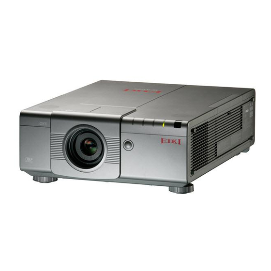
- Page 1 ® EIP-WX5000 EIP-WX5000L OWNER’S MANUAL EIKI INDUSTRIAL CO., LTD.
- Page 2 IMPORTANT • • • • • For your assistance in reporting the loss or theft of your Projector, please record Model No.: the Model and Serial Numbers located on the side of the projector and retain this information. • • • • • Before recycling the packaging, please ensure that you have checked the contents Serial No.: of the carton thoroughly against the list of “Supplied accessories”...
- Page 3 2. CONSUMER PRODUCT SAFETY ACT To ensure that you will promptly receive any safety notification of inspection, modification, or recall that EIKI may be required to give under the 1972 Consumer Product Safety Act, PLEASE READ CAREFULLY THE IMPORTANT “LIMITED WARRANTY” CLAUSE.
-
Page 4: Product Disposal
U.S.A. ONLY Caution Concerning Lamp Replacement See “Replacing the Lamp” on page 71. This EIKI projector uses a DLP ® chip. This very sophisticated panel contains 1,024,000 pixels (micromirrors). As with any high technology electronic equipment such as large screen TVs, video systems and video cameras, there are certain acceptable tolerances that the equipment must conform to. -
Page 5: How To Read This Owner's Manual
How to Read This Owner’s Manual • • • • • In this owner’s manual, the illustrations and on-screen displays are simplified for explana- tion. This may differ from the actual on-screen display. Buttons used in this Buttons used in this operation operation Button used in... -
Page 6: Table Of Contents
Quick Start ............ 19 Setup Setting Up the Projector ......21 Setting Up the Projector ........21 Standard Zoom Lens (AH-55501 : Standard Equipment with EIP-WX5000) ..... 22 Projecting a Reversed Image ......23 Connections Connecting the Projector to Other Equipment ..........24 Controlling the Projector by a Computer ... - Page 7 Useful Features Menu Items ........... 42 Shifting the Projected Image Vertically (Digital Shift) ..........57 Using the Menu Screen ....... 47 Setting On-screen Display ......... 57 Menu Selections ..........47 Setting the Video System ........57 Picture Adjustment (“Picture” menu) ..49 Capturing Projected Images ......
- Page 8 Contents SETUP MANUAL Refer to the “SETUP MANUAL” contained on the supplied CD-ROM for details. Setting up the Screen ........2 Controlling the Projector Using RS-232C Screen Size and Projection Distance ... 3 or Telnet ........... 34 Connecting Pin Assignments ..... 11 Stack Projection ...........
-
Page 9: How To Access The Pdf Owner's Manuals
How to Access the PDF Owner’s Manuals PDF owner’s manuals in several languages are included in the CD-ROM, so that you can ® ® work with the projector. To utilize these manuals, you need to install Adobe Reader on your ®... -
Page 10: Important Safeguards
IMPORTANT SAFEGUARDS CAUTION : Please read all of these instructions before you operate this product and save these instructions for later use. Electrical energy can perform many useful functions. This product has been engineered and manufactured to assure your personal safety. BUT IMPROPER USE CAN RESULT IN POTENTIAL ELECTRICAL SHOCK OR FIRE HAZARDS. - Page 11 ■ When placing the projector in a high posi- Internal cleaning should only be performed tion, make certain it is carefully secured to by an EIKI Authorized Dealer or Service Cen- avoid personal injury caused by the projec- ter. tor falling down.
- Page 12 IMPORTANT SAFEGUARDS Do not block the intake and exhaust Using the projector in other countries ■ The power supply voltage and the shape of vents. ■ Allow at least 11 inches (30 cm) of space the plug may vary depending on the region between the exhaust vent and the nearest or country you are using the projector in.
-
Page 13: Accessories
<9NK3090204900> <9NK3090152700> Use the power cord that corresponds to the wall outlet in your country. RGB cable Lens cap (10' (3.0 m)) (Only supplied with EIP-WX5000) • Projector manual and technical Dustproof cap reference CD-ROM <9NK3080431000> (Only supplied with EIP-WX5000L) •... -
Page 14: Throw Distance
No lens is attached to EIP-WX5000L. The standard zoom lens is attached to EIP-WX5000. The optional lenses from EIKI are also available for specialized application. Please see your nearest EIKI Authorized Dealer for details on all the lenses. (Refer to the lens owner’s manual when using a lens.) Throw Distance The graph below is for 100-inch (254 cm) screen with 16:10 normal mode. -
Page 15: Part Names And Functions
Part Names and Functions Numbers in refer to the main pages in this owner’s manual where the topic is explained. Projector Rear View H&V LENS SHIFT button KEYSTONE button For shifting the lens horizontally For entering the Keystone and vertically. Correction mode. - Page 16 Part Names and Functions Numbers in refer to the main pages in this owner’s manual where the topic is explained. Projector (Rear View) Terminals Refer to “Connecting the Projector to Other Equipment” on pages 24–26. HDMI terminal COMPUTER/COMPONENT 2 Terminal for HDMI input. terminals BNC terminals for computer RGB and component signals...
-
Page 17: Remote Control
Numbers in refer to the main pages in this owner’s manual where the topic is explained. Remote Control FOCUS buttons For adjusting the focus. ADJ./MOUSE switch STANDBY-ON button For switching the remote control For turning the power on or modes. putting the projector into standby mode. -
Page 18: Using The Remote Control
Using the Remote Control Front View Remote control sensor Usable Range The remote control can be used to control the projector within the ranges shown in the il- lustration. Remote control signal transmitters 23' (7 m) Note • The signal from the remote control can be re- flected off a screen for easy operation. -
Page 19: Using The Remote Control With A Signal Cable
Using the Remote Control with a Signal Cable When the signals from the remote control cannot be reached due to the positioning of the projector, use a ø3.5 mm minijack cable to connect the remote control to the projector. Now you can control the projector with the remote control. -
Page 20: Using The Remote Control As A Wireless Computer Mouse
Using the Remote Control Using the Remote Control as a Wireless Computer Mouse When connecting the supplied remote re- Computer Remote receiver ceiver to the computer, you can use the re- mote control as the wireless computer mouse. Connect the supplied remote re- ceiver to the USB terminal on the computer. -
Page 21: Quick Start
Quick Start This section shows the basic operation (projector connecting with the computer). For details, see the page described below for each step. Setup and Projection In this section, connection of the projector and the computer is explained using one example. Place the projector facing a screen Page 21 Connect the projector to the computer and plug the power... - Page 22 Quick Start Adjust the angle Adjust the projector angle: • • • • • Shift the lens horizontally and vertically. 1 1 1 1 1 Press H&V LENS SHIFT on the projector or on the remote control. 2 2 2 2 2 Press ', ", \ or | on the projector or the remote control.
-
Page 23: Setting Up The Projector
Setting Up the Projector Setting Up the Projector For optimal image quality, position the projector perpendicular to the screen with the projector’s feet flat and level. Doing so will eliminate the need for Keystone correction and provide the best image quality. Note •... -
Page 24: Standard Zoom Lens (Ah-55501 : Standard Equipment With Eip-Wx5000)
Setting Up the Projector Standard Zoom Lens (AH-55501 : Standard Equipment with EIP-WX5000) F2.5, f=25.5-32 mm 16:10 Signal Input (Normal Mode) Distance from the lens center to Distance from the lens Picture (Screen) size Projection distance [L] the bottom of the image [H] center to the center of Diag. -
Page 25: Projecting A Reversed Image
• When using a mirror, ensure that both the projector and the mirror are carefully placed so the projected light does not shine into the eyes of the audience. Ceiling-mount Setup ■ It is recommended that you use the optional EIKI ceiling-mount adaptor and unit for this installation. Before mounting the projector, contact your nearest EIKI Autho- rized Dealer or Service Center to obtain the recommended ceil- ing-mount adaptor and unit (sold separately). -
Page 26: Connecting The Projector To Other Equipment
Connecting the Projector to Other Equipment Before connecting, ensure that the power cord of the projector is unplugged from the AC outlet and turn off the equipment to be connected. After making all connections, turn on the projector and then the other pieces of equipment. - Page 27 Equipment Terminal on connected equipment Cable Terminal on the projector HDMI digital output terminal HDMI cable (commercially available) HDMI Video equipment, Camera, Video game DVI-D DVI Digital cable (commercially available) DVI digital output terminal Audio output terminal ø3.5 mm stereo minijack to RCA audio cable (commercially available) 5 BNC cable (commercially available) RGB video output terminal...
- Page 28 Connecting the Projector to Other Equipment Equipment Terminal on connected equipment Cable Terminal on the projector Video equipment, S-VIDEO S-video output terminal S-video cable (commercially available) Camera, Video game Audio output terminal RCA audio cable (commercially available) VIDEO Video output terminal Video cable (commercially available) Audio output terminal RCA audio cable (commercially available)
-
Page 29: Controlling The Projector By A Computer
Controlling the Projector by a Computer When the RS-232C terminal on the projector is connected to the RS-232C serial terminal on the computer, or when the LAN terminal on the projector is connected to the LAN terminal on the computer, the computer can be used to control the projector. Refer to the “SETUP MANUAL” contained on the supplied CD-ROM for details. -
Page 30: Turning The Projector On/Off
Turning the Projector On/Off Supplied Power cord Connecting the Power Cord accessory Plug the supplied power cord into the Rear view AC socket on the rear of the projector. Then plug into the AC outlet. Turning the Projector On To AC socket Before performing the steps in this section, connect any equipment that you use with the To AC outlet... -
Page 31: Image Projection
Image Projection Shifting the Lens In addition to the zoom function and adjustment of projection angle using the adjust- ment feet, you can adjust the position of the projection using the lens shift function. This is a useful function in cases such as when the screen cannot be moved. When moving upward or downward When moving in the left and right direction Adjustable... -
Page 32: Using The Adjustment Feet
Image Projection Press H&V LENS SHIFT on the projector or on the remote control. H&V LENS SHIFT button • Pressing ENTER on the projector or on the remote control displays the test pat- Mouse/adjustment tern. Checking the test pattern is useful button for more accurate adjustment. -
Page 33: Adjusting The Focus
Adjusting the Focus Press FOCUS +/– on the projector ZOOM buttons or on the remote control to adjust the FOCUS buttons focus. ▼On-screen display Info • It is recommended that the focus be adjusted after the projector has warmed up for at least 30 minutes. -
Page 34: Correcting Trapezoidal Distortion
Image Projection Correcting Trapezoidal Distortion When the image is projected either from the top or from the bottom towards the screen at an angle, the image becomes distorted trapezoidally. The function for correcting trapezoidal distortion is called Keystone Correction. There are the two types of the Keystone Correction. 1) “GEOMETRIC ADJUSTMENT”... -
Page 35: Geometric Adjustment
GEOMETRIC ADJUSTMENT ▼On-screen display Press KEYSTONE on the pro- jector or on the remote control repeatedly until “GEOMETRIC ADJUSTMENT” is displayed. Press the buttons below to ad- just the position, size or focus of the projected image. • Match screen’s four sides to green test pattern. - Page 36 Image Projection H&V KEYSTONE ▼On-screen display Press KEYSTONE on the pro- jector or on the remote control repeatedly until “H&V KEY- STONE” is displayed. • When the correction has already been made with “GEOMETRIC ADJUST- MENT”, the confirmation message for resetting the correction before “H&V KEYSTONE”...
- Page 37 IMAGE RESIZING Press ', ", \ or | to correct ' / " / \ / | (Adjustment with the image distortion. Press KEYSTONE to set the position.
-
Page 38: Switching The Input Mode
Image Projection Switching the Input Mode '/" buttons Select the appropriate input mode for the con- nected equipment. Press COMPUTER1/2, DVI, HDMI, COMPUTER1/2, VIDEO or S-VIDEO on the remote DVI, HDMI, VIDEO control to select the input mode. and S-VIDEO buttons ■... -
Page 39: Turning Off The Sound Temporarily
Turning Off the Sound Temporarily Press MUTE on the remote control to temporarily turn off the sound. MUTE button Note • Pressing MUTE again will turn the sound back on. "On-screen display Displaying an Enlarged Portion of an Image Graphs, tables and other portions of projected images can be enlarged. -
Page 40: Freezing A Moving Image
Image Projection Freezing a Moving Image Press FREEZE on the remote control. FREEZE button • The projected image is frozen. Press FREEZE again to return to the moving image from the currently connected equipment. Selecting the Picture Mode You can select the suitable picture mode for the UNDO button projected image, such as movie or video game. -
Page 41: Resize Mode
This function allows you to modify or customize the resize mode to enhance the input image. Depend- ing on the input signal, you can choose a desired image. Resize Mode Mouse/adjustment button Press RESIZE on the remote control. ('/"/\/|) • Pressing RESIZE changes the display as shown in the tables below. - Page 42 Image Projection VIDEO/DTV Input signal Output screen image Video/DTV Image Type NORMAL AREA ZOOM V-STRETCH STRETCH SMART STRETCH 4:3 aspect ratio 480I, 480P, 576I, 576P, NTSC, PAL, SECAM Squeeze Letter box 16:9 aspect ratio 720P, 1035I, 1080I, 1080P 16:9 aspect ratio —...
-
Page 43: Hiding The Projected Image (Shutter Function)
Hiding the Projected Image (Shutter function) This function allows you to tempo- rarily hide the projected image. SHUTTER buttons Press SHUTTER CLOSE. • The projected image is hidden. Pressing SHUTTER OPEN will turn the projected image back Note In the following cases, hiding will be cancelled automatically. -
Page 44: Menu Items
Menu Items The following shows the items that can be set in the projector. “Picture” menu COMPUTER1/2, DVI, HDMI Main Menu Sub Menu Standard Picture Picture Mode Presentation Page Page Movie Custom Contrast Bright Color Tint Green Blue Sharp Page 4500K CLR Temp Page... - Page 45 “Picture” menu VIDEO/S-VIDEO Main Menu Sub Menu Picture Picture Mode Standard Presentation Page Page Movie Custom Contrast Bright Color Tint Green Blue Sharp Page 4500K CLR Temp Page 10500K Progressive 2D Progressive 3D Progressive Page Film Mode Standard C.M.S. Adjustment Custom 1 Page Custom 2...
- Page 46 Menu Items “C.M.S.” menu Main Menu Sub Menu C.M.S. Standard C.M.S. Adjustment Custom 1 Page Page Custom 2 Custom 3 sRGB Target [R] Red [Y] Yellow Page [G] Green [C] Cyan [B] Blue [M] Magenta Lightness Page Chroma Page Page Reset (This Color) Page Reset (All Colors)
- Page 47 “Audio” menu Sub Menu Main Menu Audio Balance Page Treble Bass Reset Page Audio Out Page Speaker Page “Options 1” menu Main Menu Sub Menu Options 1 Pict in Pict Page Page Resize Normal Full Page Dot By Dot Area Zoom V-Stretch Stretch Smart Stretch...
- Page 48 Menu Items “Options 2” menu “Language” menu Main Menu Sub Menu Main Menu Sub Menu Old Password Options 2 Password English Language New Password Deutsch Page Page Page Reconfirm Español Nederlands Both Lamps Lamp Mode Français Lamp 1 Only Italiano Page Lamp 2 Only Svenska...
-
Page 49: Using The Menu Screen
Using the Menu Screen MENU button Adjustment MENU button buttons ('/"/\/|) ENTER button Mouse/adjustment button ('/"/\/|) UNDO button ENTER button UNDO button Menu Selections • This operation can also be performed by using the buttons on the projector. Example: “Picture” screen menu for Press MENU. - Page 50 Using the Menu Screen There are two methods of adjustment de- pending on the menu item. Use the appli- cable method from Example 1 or 2 shown below. Example 1: Adjusting “Bright” ' ' or " " " " " to select the item Press ' you want to adjust.
-
Page 51: Picture Adjustment ("Picture" Menu)
Picture Adjustment (“Picture” menu) Menu operation Page | | | | | Page 1 | | | | | Page 2 1 1 1 1 1 Selecting the Picture Mode 2 2 2 2 2 Adjusting the Image This function allows you to select the picture Select a picture mode before adjusting the im- mode in accordance with brightness of the room age. -
Page 52: Adjusting The Color Temperature
Picture Adjustment (“Picture” menu) Menu operation Page 3 3 3 3 3 Adjusting the Color Temperature 5 5 5 5 5 Reducing Image Noise (DNR) Video digital noise reduction (DNR) provides high Selectable items Description quality images with minimal dot crawl and cross 4500K For lower color temperature for warmer, color noise. -
Page 53: Selecting The Signal Type
Menu operation Page 6 6 6 6 6 Selecting the Signal Type 7 7 7 7 7 Selecting the Dynamic Range When using an input mode other than S-VIDEO or VIDEO input, set the signal type setting to the cor- An optimum picture may not be displayed if a DVI-D responding input signal type (RGB or Component). -
Page 54: Color Management System ("C. M. S." Menu)
Color Management System (“C. M. S.” menu) Menu operation Page 3 3 3 3 3 Setting the Brightness of the Target Color This function allows you to set the brightness of the selected target color. Press \ Press | For less brightness of the For more brightness of the target color target color... -
Page 55: Computer Image Adjustment ("Fine Sync" Menu)
Computer Image Adjustment (“Fine Sync” menu) Menu operation Page 2 2 2 2 2 Saving Adjustment Settings This projector allows you to store up to seven adjustment settings for use with various com- puters. 3 3 3 3 3 Accessing Adjustment Settings Adjustment settings stored in the projector can be easily accessed. -
Page 56: Checking The Input Signal
Computer Image Adjustment (“Fine Sync” menu) Menu operation Page 7 7 7 7 7 Setting the Auto Sync 5 5 5 5 5 Checking the Input Signal Display Function You can check the input signal information. Used to set the display during Auto Sync. Selectable items Description 6 6 6 6 6 Auto Sync Adjustment... -
Page 57: Audio Adjustment ("Audio" Menu)
Audio Adjustment (“Audio” menu) Menu operation Page Note When the projector is connected to audio equipment: • It is recommended that “FAO” be selected on “Audio Out”. Because the audio signal from the audio equip- ment does not vary in strength with the volume level of the projector, you can enjoy better sound. -
Page 58: Using The "Options 1" Menu
Using the “Options 1” Menu COMPUTER1/2, DVI, HDMI Menu operation Page Note • You can press ' / " / \ / | on the projector or on the remote control to change the location of the inset picture image. (The inset picture frame will be displayed. -
Page 59: Shifting The Projected Image Vertically (Digital Shift)
Menu operation Page 3 3 3 3 3 Shifting the Projected 5 5 5 5 5 Setting the Video System Image Vertically (Digital The video input system mode is factory preset Shift) to “Auto”; however, a clear picture from the con- nected audio-visual equipment may not be re- ceived, depending on the video signal difference. -
Page 60: Selecting The Background Image
Using the “Options 1” Menu Menu operation Page 7 7 7 7 7 Selecting the Background 0 0 0 0 0 Detecting the Input Image Signals Automatically Selectable items Description Selectable items Description Logo Default image Automatically searches for and switches to Custom User customized image (e.g. -
Page 61: Setting The System Lock Function
• If you lose or forget your keycode, contact your ton on the remote control or on the projec- nearest EIKI Authorized Dealer or Service Cen- tor as an individual button, even if they share ter (see page 81). Even if the product warranty the same button name. - Page 62 Using the “Options 1” Menu Changing the keycode When the system lock is set If you have set the system lock, enter the keycode and follow the procedure below to release the system lock. ▼Input screen for keycode Press the 4 buttons on the remote control or on the projector to enter the preset keycode in “Old Code”.
-
Page 63: Helpful Functions Set During Installation ("Options 2" Menu)
Helpful Functions Set during Installation (“Options 2” menu) Menu operation Page Changing the password ' ' , " " " " " and | | | | | to enter the pass- Press ' word in “Old Password” and press ENTER. -
Page 64: Setting The Lamp Mode
Helpful Functions Set during Installation (“Options 2” menu) Menu operation Page 2 2 2 2 2 Setting the Lamp Mode 4 4 4 4 4 Reversing/Inverting Projected Images This function allows you to select the usage of the two lamps installed in the projector. This projector is equipped with a reverse/invert image function that allows you to reverse or in- Selectable items... -
Page 65: Shortcut To Make Projector Stack Settings
Menu operation Page 6 6 6 6 6 Shortcut to Make 8 8 8 8 8 Bypassing Unused Input Projector Stack Settings Selections Normally, settings via web browser are required for This function allows you to skip the input mode the stack projection. -
Page 66: Selecting The Transmission Speed (Rs-232C)
Helpful Functions Set during Installation (“Options 2” menu) Menu operation Page q q q q q Selecting the Transmission e e e e e Setting the LAN/RS232C Speed (RS-232C) When the LAN/RS232C has been set to “Enable”, the LAN/RS232C is activated and power is con- Make sure that both the projector and computer sumed even in the standby mode. -
Page 67: Helpful Functions Set During Installation ("Options 2" Menu)/Using The Other Menus ("Language" And "Status" Menus)
Helpful Functions Set during Installation (“Options 2” menu)/Using the Other Menus (“Language” and “Status” menus) Menu operation Page t t t t t Setting the TCP/IP y y y y y Service Mode Set the TCP/IP manually. Only the service centers use the menu. Do not use the menu. -
Page 68: Maintenance
Maintenance Cleaning the projector Cleaning the air vents and the intake vent cover ■ Ensure the power cord is unplugged before clean- ■ Use a vacuum cleaner to clean dust from the ex- ing the projector. haust vent, the intake vents and the intake vent cover ■... -
Page 69: Cleaning And Replacing The Dust Filters
Cleaning and Replacing the Dust Filters Cleaning the Dust Filters STANDBY-ON button Info • The dust filters should be cleaned every 100 hours of use. Clean the filters more often when the projector is used in a dusty or smoky location. Press STANDBY-ON on the pro- jector or on the remote control to put the projector into standby... -
Page 70: Replacing The Dust Filters
Info • If the filters become too dirty to clean effec- Remove tively, purchase new ones (9NK3243101400) from your nearest EIKI Authorized Dealer or Service Center. After removing the filter cover (see step 2 of “Cleaning the Dust Filters”), remove the dust filters, then replace with new ones. -
Page 71: Maintenance Indicators
Maintenance Indicators ■ The warning lights on the projector indicate problems inside the projector. ■ If a problem occurs, either the temperature warning indicator or the lamp indicator will illuminate red, and the projector will enter the standby mode. After the projector has entered the standby mode, follow the procedures given below. - Page 72 The internal • Cooling fan break- • Take the projector to your nearest Red on temperature is warning down EIKI Authorized Dealer or Service (Standby) abnormally high. indicator • Internal circuit failure Center for repair. • Clogged air intake • Clean the air vents and the dust •...
-
Page 73: Regarding The Lamp
■ Carefully change the lamp by following the instructions described in this section. *If you wish, you may have the lamp replaced at your nearest EIKI Authorized Dealer or Service Center. * If the new lamp does not illuminate after replacement, take your projector to the nearest EIKI Authorized Dealer or Service Center for repair. -
Page 74: Removing And Installing The Lamp Unit
Regarding the Lamp Removing and Installing the Lamp Unit Optional Lamp unit accessory AH-55001 Warning! • Do not remove the lamp unit from the pro- jector right after use. The lamp and parts around the lamp will be very hot and may cause burn or injury. - Page 75 Securing screws Remove the lamp unit. • Loosen the securing screws (two for each lamp) from the lamp unit. Hold the lamp unit by the handle and pull it in the direction of the arrow. At this time, keep Handle the lamp unit horizontal and do not tilt it.
-
Page 76: Resetting The Lamp Timer
Regarding the Lamp Resetting the Lamp Timer Reset the lamp timer after replacing the lamp. Info • Make sure to reset the lamp timer only when replacing the lamp. If you reset the lamp timer and continue to use the same lamp, this may cause the lamp to become damaged or explode. -
Page 77: Computer Compatibility Chart
Computer Compatibility Chart The table below lists signal codes that are compatible with the projector. When the images are distorted or cannot be projected, adjust the output signal of your computer and so forth while referring to the table below. Computer •... - Page 78 Computer Compatibility Chart Note • This projector may not be able to display images from notebook computers in simultaneous (CRT/LCD) mode. Should this occur, turn off the LCD display on the notebook computer and output the display data in “CRT only” mode. Details on how to change display modes can be found in your notebook computer owner’s manual.
-
Page 79: Attaching The Optional Lens
Attaching the Optional Lens Do not attempt to exchange the lens when the STANDBY-ON button projector is installed hanging from the ceiling. Injury may occur if the lens cover and lens fall. H&V LENS SHIFT button Before exchanging the lens, reset lens shift to the center position. - Page 80 Attaching the Optional Lens Remove the lens cap from a re- placement lens. Info If you try to attach the lens to the projector without removing this cap, the optional lens attachment part can be damaged. Insert the hook of the replacement lens to the notch, and turn the lens in the direction of the arrow.
-
Page 81: Troubleshooting
Troubleshooting Problem Check Page • Projector power cord is not plugged into the wall outlet. • Power to the external connected devices is off. — • The selected input mode is wrong. • Cables are incorrectly connected to the projector. 24–27 •... - Page 82 Troubleshooting Problem Check Page An unusual sound is • If the picture is normal, the sound is due to cabinet shrinkage — occasionally heard caused by room temperature changes. This will not affect from the cabinet. operation or performance. Maintenance •...
-
Page 83: Specifications
EIP-WX5000 : 58.5 lbs. (26.5 kg) EIP-WX5000L : 55.2 lbs. (25.0 kg) As a part of policy of continuous improvement, EIKI reserves the right to make design and specification changes for product improvement without prior notice. The performance speci- fication figures indicated are nominal values of production units. There may be some devia-... -
Page 84: Index
Index AC socket ............... 28 L-CLICK button .............. 18 ADJ./MOUSE switch ............17 Lens cap ................ 13 Adjustment buttons ............47 Lens cover ..............77 Adjustment feet .............. 30 MAGNIFY buttons ............37 Advanced intelligent compression ........ 75 MENU button ..............47 All Reset ................ - Page 85 U.S.A. Canada EIKI International, Inc. EIKI CANADA - Eiki International, Inc. 30251 Esperanza P.O. Box 156, 310 First St. - Unit 2, Rancho Santa Margarita Midland, ON, L4R 4K8, Canada CA 92688-2132 Tel : 800-563-3454 (705)-527-4084 U.S.A. Fax : 800-567-4069 (705)-527-4087 Tel : 800-242-3454 (949)-457-0200 E-Mail : canada@eiki.com...
Need help?
Do you have a question about the EIP-WX5000 and is the answer not in the manual?
Questions and answers