Table of Contents
Advertisement
Quick Links
USE AND MAINTENANCE MANUAL
TRANSLATION OF THE ORIGINAL INSTRUCTIONS – ENGLISH
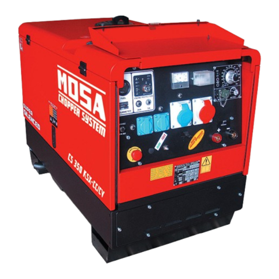
CS 350 KSX CC/CV
• Motosaldatrice
• Schweißaggregat
• Engine Driven Welder
• Motosoldadora
• Motosoudeuse
• По Вышкам
• Motosoldadoras
• Lassers
M A D E
I N
I T A L Y
language
Codice
Code
Code
Codigo
C0QB30119003
Kodezahl
Código
Код
Code
Edizione
Edition
Édition
Edición
01.2016
Ausgabe
Edição
Издание
Editie
Advertisement
Table of Contents

Related Manuals for MOSA Weld CS 350 KSX CC


Summary of Contents for MOSA Weld CS 350 KSX CC
- Page 1 USE AND MAINTENANCE MANUAL TRANSLATION OF THE ORIGINAL INSTRUCTIONS – ENGLISH Codice CS 350 KSX CC/CV Code Code Codigo C0QB30119003 Kodezahl Código Код Code Edizione Edition Édition • Motosaldatrice • Schweißaggregat Edición 01.2016 • Engine Driven Welder • Motosoldadora Ausgabe •...
- Page 3 DESCRIPTION OF THE MACHINE REV.0-01/16 The engine driven welder is a unit which ensures the function as: a) a current source for are welding b) a current source for the auxiliary generation The welding generator set is a source of DC electric power, driven by an internal combustion engine, which allows to perform arc welding processes with different types of electrodes and, with the CC/CV version, also wire welding.
- Page 5 Index REV.0-01/16 DESCRIPTION OF THE MACHINE M 1.01 COPYRIGHT M 1.1 NOTES M 1.4 CE MARK M 1.5 TECHNICAL DATA M 1.6 TECHNICAL DATA SAFETY PRECAUTIONS M 2.1 SYMBOLS M 2.5 -…. INSTALLATION AND ADVICE BEFORE USE M 2.6 INSTALLATION AND ADVICE M 2.7 INSTALLATION AND DIMENSIONS UNPACKING...
- Page 6 Copyright 1.01 REV.0-10/02 ATTENTION This use and maintenance manual is an important part of the machines in question. The assistance and maintenance personel must keep said manual at disposal, as well as that for the engine and alternator (if the machine is synchronous) and all other documentation about the machine.
-
Page 7: Notes About The Manual
Notes REV.1-03/14 INFORMATION INFORMATION OF GENERAL TYPE In the envelope given together with the machine and/or Dear Customer, set you will find: the manual for Use Maintenance and We wish to thank you for having bought a high quality set. Spare Parts, the manual for use of the engine and the tools (if included in the equipment), the guarantee (in the Our sections for Technical Service and Spare Parts will... - Page 8 CE MARKING REV.7-02/14 Any of our product is labelled with CE marking attesting its conformity to appliable directives and also the fulfillment of safety requirements of the product itself; the list of these directives is part of the declaration of conformity included in any machine standard equipment. Here below the adopted symbol: CE marking is clearly readable and unerasable and it can be either part of the data-plate.
- Page 9 Technical data REV.0-01/16 Technical data CS 350 KSX CC/CV GENERATOR Three-phase generation 10 kVA / 400 V / 14.4 A Single-phase generation 5 kVA / 230 V / 21.7 A Single-phase generation 2.5 kVA / 110 V / 22.7 A...
-
Page 10: Static Characteristics
Technical data REV.0-01/16 Technical data CS 350 KSX CC/CV C.C. WELDING Duty cycle 350A/35% - 300A/60% - 250A/100% Welding current electronic regulation 20 - 350A Open circuit voltage C.V. WELDING Duty cycle 300A/60% - 250A/100% Welding voltage regulation 14V - 44V C.C. - Page 11 WARNINGS REV.1-02/14 The installation and general warnings regarding operations are aimed achieving correct use of the machine and/or apparatus in the place where it is used as a genset and/or motor welder. - Advice to the User about the safety: + NB: The information contained in the manual can be changed without notice.
- Page 12 SYMBOLS AND SAFETY PRECAUTIONS REV.2-06/10 SYMBOLS PROHIBITIONS No harm for persons Use only with safety clothing - STOP - Read absolutely and be duly attentive It is compulsory to use the personal protection means given in equip- ment. Use only with safety clothing - Read and pay due attention It is compulsory to use the personal protection means given in equipment.
-
Page 13: Gasoline Engines
INSTALLATION AND ADVICE REV.1-06/07 Check that the air gets changed completely and the hot INSTALLATION AND ADVICE BEFORE USE air sent out does not come back inside the set so as to cause a dangerous increase of the temperature. GASOLINE ENGINES Use in open space, air swept or vent exhaust gases, which contain the deathly carbone oxyde, far from the work area. - Page 14 Installazione e dimensioni Luftzirkulation und abmessungen Installation and dimensions Instalación y dimensiones Installation et dimensions Instalação e dimensões REV.0-01/16...
- Page 15 UNPACKING REV.1-02/04 NOTE + Be sure that the lifting devices are: correctly mounted, adequate for the weight of the machine with it’s pack- aging, and conforms to local rules and regulations. When receiving the goods make sure that the product has not suffered damage during the transport, that there has not been rough handling or taking away of parts contained inside the packing or in the set.
- Page 16 TRANSPORT AND DISPLACEMENTS COVERED UNITS REV.1-06/10 NOTE Transportation must always take place with the engine off, electrical cables and starting battery disconnected and fuel tank empty. Be sure that the lifting devices are: correctly mounted, adequate for the weight of the machine with it’s packaging, and conform to local rules and regulations.
- Page 17 TRANSPORT AND DISPLACEMENTS COVERED UNITS REV.2-09/11 NOTE Transportation must always take place with the engine off, electrical cables and starting battery disconnected and fuel tank empty. Be sure that the lifting devices are: correctly mounted, adequate for the weight of the machine with it’s packaging, and conform to local rules and regulations.
- Page 18 CTM330 ASSEMBLY CTL330 6.17 REV.0-06/10 ATTENTION The CTL accessory cannot be removed from the machine and used separately (actioned manually or following vehicles) for the transport of loads or anyway for used different from the machine movements. TRAILERS The machines provided for assembling the accessory (slow towing trolley) can be towed up to a maximum speed of 40 Kms/hour on asphalted surfaces.
-
Page 19: Grounding Connection
Set-up for operation (Engine diesel) Air cooled systems REV.2-03/15 BATTERY WITHOUT MAINTENANCE OIL BATH AIR FILTER The starter battery is supplied alre- Fill the air filter using the same engine oil up to the ady charged and ready for use. level indicated on the filter. - Page 20 STARTING THE ENGINE REV.0-01/16 Check daily If the motor does not start within 15 seconds, the non starting alert will intervene: the two LEDs “Engine running” and “glow plug” will flash al- ternately (see motor protection description). D) - At any time it is possible to stop the engine by NOTE turning the key in an anti-clockwise direction (OFF position).
-
Page 21: Arresto D'emergenza
Arresto del motore TS 350 YSX BC CS 350 LSX CC/CV REV.0-09/07 ARRESTO Per un arresto in condizioni normali eseguire la seguente procedura: 1. Interrompere il processo saldatura in atto 2. Interrompere l’erogazione di generazione au- siliaria c.a. sezionando i carichi oppure aprendo l’interruttore differenziale (D). 3. Lasciare girare il motore senza carico per alcuni minuti. Portare al minimo il numero di giri del motore, deviatore giri motore su "autoidle" o accelerato- re al minimo per le macchine con acceleratore manuale. - Page 22 CONTROLS LEGENDE REV.3-04/13 Hydraulic oil level light Exclusion indicating light PTO HI Selection push button 30 l/1' PTO HI Welding socket ( + ) Auxiliary current push button Battery voltmeter Welding socket ( - ) Fuel level light Remote control socket Earth terminal E.A.S. PCB Button indicating light 20 l/1' PTO HI A.C. socket Control unit for generating sets QEA Commutator/switch, serial/parallel Accelerator lever Thermal-magnetic circuit breaker Ground fault interrupter ( 30 mA ) Feed pump Selection push button 20 l/1' PTO HI Engine control unit and economiser 48V D.C. socket Water temperature indicator Engine air filter Ammeter Oil level dipstick Frequency meter Engine oil reservoir cap Frequency rpm regulator 24A Hydraulic oil reservoir cap Voltmeter regulator 24B Water filling cap Fuse Fuel prefilter Stop switch Fuel tank cap Warning light, high temperature Muffler...
- Page 23 Comandi Bedienelemente Controls Mandos Commandes REV.0-01/16...
-
Page 24: Welding Mode Selection
WELDING ANALOG CONTROL (350A) 33.2 REV.0-06/10 WELDING MODE SELECTION VOLTAGE AND CURRENT REGULATION The Welding Analogue Control unit (WAC) allows two possible control modes: Constant Current (CC) Constant Voltage (CV). The welding option with C.V. characteristic is possible only on those models which support this mode of operation. On such models there is a switch on the front panel of the welder (outside the WAC unit), which allows to select the desired mode. - Page 25 WELDING ANALOG CONTROL (350A) 33.3 REV.0-06/10 ARC FORCE REGULATION CONTACTS DESCRIPTION A (Ground) To the RC1 potentiometer – GND terminal To the RC1 potentiometer – V terminal ARC FORCE CONTR To the RC1 potentiometer – V terminal Remote connection presence contact – wire bridge towards (C) cabling side Non connected Non connected...
-
Page 26: Remote Control
USE AS WELDER REV.0-01/16 This symbol (Norm EN 60974-1 security standards for arc welders) signifies that the welder can be used in areas with increased risk of electrical shock. ATTENTION The areas, access of which is forbiden to unqua- lified personel, are: - the control switchboard (front) - the exhaust of the endothermic engine - the welding process. -
Page 27: Thermal Protection
WELDING DIGITAL CONTROL USE AS A GENERATOR REV.1-06/10 minutes to allow the thermal WARNING protection to cool down. PUSH TO Before resetting by pressing It is strictly forbidden to connect the group to RESET the central button and then the public mains and/or to any other source connect the load again. - Page 28 REMOTE CONTROL ACCESSORY USE (DSP/CS SERIES) 38.10 RC2/90° REV.3-12/11 PUSH AND SCREW TIGHT PUSH AND SCREW TIGHT The remote control RC, which regulates the welding current in the CC (STICK welding) mode and the welding voltage in the CV (MIG/MAG welding), is connected to the front panel by means of a multipole connector.
- Page 29 ACCESSORY USE REMOTE CONTROL 38.12 REV.0-06/10 PUSH AND SCREW TIGHT The remote control device for regulating the welding current is connected to the front panel by means of a multipole connector. When the remote control is connected to the remote control connector (8), it is functional and automati- cally excludes the front panel regulation.
-
Page 30: Specification
PROTECTIONS EP7 ENGINE PROTECTION 39.13 REV.0-10/07 Description Specification The EP7 includes the basic safeguards to protect an DC Supply, Battery Plant 8V up to 36 Vdc Static Outputs (short circuit proof) 200 mAdc DIESEL engine. The EP7 features 7 LEDs, 3 Static Key Switch Rating 30 A (30 secs)/80 A (5 secs) Outputs and a 30A Key Switch. - Page 31 40.1 Trouble shooting REV.0-02/11...
- Page 32 40.2 Trouble shooting REV.0-02/11...
- Page 33 40.3 Trouble shooting REV.0-02/11...
- Page 34 MAINTENANCE REV.1-01/13 WARNING ● Have qualified personnel do maintenance and troubleshooting work. ● Stop the engine before doing any work inside the machine. If for any reason the machine must be operated while working inside, pay at- tention moving parts, hot parts (exhaust manifold and muffler, etc.) electrical parts which may be unprotected when the machine is open.
-
Page 35: Gasoline Engine
STORAGE REV.0-06/07 In case the machine should not be used for more than 30 days, make sure that the room in which it is stored presents a suitable shelter from heat sources, weather changes or anything which can cause rust, corrosion or damages to the machine. - Page 36 CUST OFF REV.0-06/07 Have qualified personnel disassemble the In case of necessity for first aid and fire prevention, machine and dispose of the parts, including the see page M2.5. oil, fuel, etc., in a correct manner when it is to be taken out of service.
- Page 37 RECOMMENDED ELECTRODES (In accordance with A.W.S Standard) REV.0-10/03 The information here below are to be intended only as indicative since the above norm is much larger. For further details please see the specific norms and/or the manufacturers of the product to be used in the welding process.
- Page 38 ELECTRICAL SYSTEM LEGENDE REV.11-06/14 A : Alternator E3 : Open circuit voltage switch I6 : Start Local/Remote selector N9 : UP/DOWN button mast B : Wire connection unit F3 : Stop push-button L6 : Choke button O9 : Hydraulic unit solenoid valve C : Capacitor G3 : Ignition coil M6 : Switch CC/CV P9 : Hydraulic unit engine D : G.F.I. H3 : Spark plug N6 : Connector – wire feeder Q9 : Ignitor E : Welding PCB transformer I3 : Range switch O6 : 420V/110V 3-phase transformer...
- Page 39 Schema elettrico Electric diagram 61.1 Schemas electriques REV.0-01/16...
- Page 40 Schema elettrico Electric diagram 61.2 Schemas electriques REV.0-01/16...
- Page 41 Schema elettrico Electric diagram 61.3 Schemas electriques REV.0-01/16...
- Page 42 Schema elettrico Electric diagram 61.5 Schemas electriques REV.0-01/16...
- Page 43 Schema elettrico Electric diagram 61.6 Schemas electriques REV.0-01/16...
- Page 46 MOSA div. della BCS S.p.A. Viale Europa, 59 20090 Cusago (Milano) Italy Tel.+39 - 0290352.1 Fax +39 - 0290390466 www.mosa.it...
Need help?
Do you have a question about the CS 350 KSX CC and is the answer not in the manual?
Questions and answers