Table of Contents
Advertisement
Quick Links
USE AND MAINTENANCE MANUAL
TRANSLATION OF THE ORIGINAL INSTRUCTIONS – ENGLISH
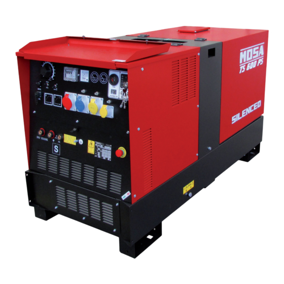
TS 600 PS-BC
• Motosaldatrice
• Schweißaggregat
• Engine Driven Welder
• Motosoldadora
• Motosoudeuse
• По Вышкам
• Motosoldadoras
M A D E
I N
I T A L Y
language
Codice
Code
Code
766059003
Codigo
Kodezahl
Código
Код
Edizione
Edition
Édition
Edición
12.2011
Ausgabe
Edição
Издание
Advertisement
Table of Contents

Related Manuals for MOSA Weld TS 600 PS-BC


Summary of Contents for MOSA Weld TS 600 PS-BC
- Page 1 USE AND MAINTENANCE MANUAL TRANSLATION OF THE ORIGINAL INSTRUCTIONS – ENGLISH Codice TS 600 PS-BC Code Code 766059003 Codigo Kodezahl Código Код Edizione Edition Édition • Motosaldatrice • Schweißaggregat Edición 12.2011 • Engine Driven Welder • Motosoldadora Ausgabe • Motosoudeuse • По Вышкам...
- Page 3 DESCRIPTION OF THE MACHINE TS 600 PS-BC REV.0-12/11 The TS 600 engine driven welder is a unit which ensures the function as: a) a current source for welding b) a current source for the auxiliary generation The welding generator set is a source of DC electric power, driven by an internal combustion engine, which allows to perform arc welding processes with different types of electrodes.
- Page 4 Quality system REV.4-03/12 UNI EN ISO 9001 : 2008 MOSA has certified its quality system according The advantages for MOSA clients are: to UNI EN ISO 9001:2008 to ensure a constant, ·Constant quality of products and services at thehigh highquality of its products. This certification covers level which the client expects;...
- Page 5 Index TS 600 PS-BC REV.0-12/11 DESCRIPTION OF THE MACHINE M 01 QUALITY SYSTEM M 1.01 COPYRIGHT M 1.1 NOTES M 1.4 CE MARK M 1.4.1 DECLARATION OF CONFORMITY M 1.5 TECHNICAL DATA M 1.6 WELDING TECHNICAL DATA M 2 - 2.1 SYMBOLS AND SAFETY PRECAUTIONS M 2.5 -….
- Page 6 Copyright 1.01 REV.0-10/02 ATTENTION This use and maintenance manual is an important part of the machines in question. The assistance and maintenance personel must keep said manual at disposal, as well as that for the engine and alternator (if the machine is synchronous) and all other documentation about the machine.
-
Page 7: Notes About The Manual
Notes REV.0-10/02 INFORMATION INFORMATION OF GENERAL TYPE In the envelope given together with the machine and/or Dear Customer, set you will find: the manual for Use Maintenance and We wish to thank you for having bought a high quality set. Spare Parts, the manual for use of the engine and the tools (if included in the equipment), the guarantee (in the Our sections for Technical Service and Spare Parts will... - Page 8 CE MARK REV.5-03/11 Any of our product is labelled with CE marking attesting its conformity to appliable directives and also the fulfillment of safety requirements of the product itself; the list of these directives is part of the declaration of conformity included in any machine standard equipment. Here below the adopted symbol: CE marking is clearly readable and unerasable and it can be either part of the data-plate.
-
Page 9: Dichiarazione Di Conformita
Dichiarazione conformità Konformitätserklärung Declaration of conformity Declaración de conformidad 1.4.1 Déclaration de conformité REV.0-06/10 BCS S.p.A. Stabilimento di Cusago, 20090 (MI) - Italia V.le Europa 59 Sede legale: Tel.: +39 02 903521 Via Marradi 1 Fax: +39 02 90390466 20123 Milano - Italia DICHIARAZIONE DI CONFORMITA' Déclaration de Conformité... - Page 10 Technical data TS 600 PS-BC REV.0-12/11 Technical data TS 600 PS-BC DC WELDING Duty cycle 600A/35% - 550A/60% - 500A/100% Welding current regulation (I scale) 20 - 600A Welding voltage GENERATOR Three-phase generation 40 kVA / 400 V / 57.7 A Single-phase generation 15 kVA / 230 V / 65.2 A...
-
Page 11: Static Characteristics
Technical data TS 600 PS-BC REV.0-12/11 Technical data D.C. WELDING Welding current electronic regulation (on 2 scales) 20-200 / 20-600A Service 600A/35% - 550A/60% - 500A/100% Striking voltage C.C. STATIC CHARACTERISTICS SIMULTANEOUS UTILISATION LIMITS WELDING CURRENT ≤100A 150A 200A 250A... -
Page 12: Symbols In This Manual
SYMBOLS AND SAFETY PRECAUTIONS REV.0-11/99 SYMBOLS IN THIS MANUAL SAFETY PRECAUTIONS DANGEROUS The symbols used in this manual are designed to call your attention to important aspects of the operation of the machine as well as potential hazards and dangers This heading warns of an immediate danger for persons for persons and things. -
Page 13: Symbols And Safety Precautions
SYMBOLS AND SAFETY PRECAUTIONS REV.2-06/10 SYMBOLS PROHIBITIONS No harm for persons Use only with safety clothing - STOP - Read absolutely and be duly attentive It is compulsory to use the personal protection means given in equip- ment. Use only with safety clothing - Read and pay due attention It is compulsory to use the personal protection means given in equipment. - Page 14 INSTALLATION AND ADVICE BEFORE USE REV.0-06/00 The installation and the general advice concerning the operations, are finalized to the correct use of the ma- chine, in the place where it is used as generator group and/or welder. Stop engine when fueling Do not touch electric devices if you are barefoot or with wet Do not smoke, avoid flames, sparks or electric tools when fueling.
- Page 15 PRECAUTION (ENGINE DRIVEN WELDER) 2-5- REV.0-06/07 INSTALLATION AND ADVICE BEFORE USE The operator of the welder is responsible for the security of the people who work with the welder and for those in the vicinity. The security measures must satisfy the rules and regulations for engine driven welders. The information given below is in addition to the local security norms.
-
Page 16: Gasoline Engines
INSTALLATION AND ADVICE REV.1-06/07 Check that the air gets changed completely and the hot INSTALLATION AND ADVICE BEFORE USE air sent out does not come back inside the set so as to cause a dangerous increase of the temperature. GASOLINE ENGINES Use in open space, air swept or vent exhaust gases, which contain the deathly carbone oxyde, far from the work area. - Page 17 Installazione e dimensioni Luftzirkulation und abmessungen Installation and dimensions Instalación y dimensiones TS 600 PS-BC Installation et dimensions REV.0-12/11...
- Page 18 UNPACKING REV.1-02/04 NOTE + Be sure that the lifting devices are: correctly mounted, adequate for the weight of the machine with it’s pack- aging, and conforms to local rules and regulations. When receiving the goods make sure that the product has not suffered damage during the transport, that there has not been rough handling or taking away of parts contained inside the packing or in the set.
- Page 19 TRANSPORT AND DISPLACEMENTS COVERED UNITS REV.1-06/10 NOTE Transportation must always take place with the engine off, electrical cables and starting battery disconnected and fuel tank empty. Be sure that the lifting devices are: correctly mounted, adequate for the weight of the machine with it’s packaging, and conform to local rules and regulations.
- Page 20 CTL 35 - 45 - 50 - 95 ASSEMBLY REV.1-03/06 ATTENTION The CTL accessory cannot be removed from the machine and used separately (actioned manually or following vehicles) for the transport of loads or anyway for used different from the machine movements. TRAILERS The machines provided for assembling the CTL accessory (slow towing trolley) can be towed up to a maximum speed of 40 Kms/hour on asphalted surfaces.
- Page 21 Set-up for operation Water cooled systems REV.1-09/05 AIR FILTER BATTERY WITHOUT MAINTENANCE Connect the cable + (positive) Check that the dry air filter is correctly installed and to the pole + (positive) of the that there are no leaks around the filter which could battery (after having taken lead to infiltrations of non-filtered air to the inside of...
-
Page 22: Cooling Liquid
Set-up for operation Water cooled systems REV.1-02/11 COOLING LIQUID GROUNDING CONNECTION ATTENTION The grounding connection to an earthed installation Do not remove the radiator tap with the is obligatory for all models equipped with a diffe- motor in operation or still hot, as the rential switch (circuit breaker). -
Page 23: Starting The Engine
STARTING THE ENGINE DSP 600 / TS 600 PS-BC REV.0-12/11 Check daily 4. The engine starts up at its operating speed, 1500 or 1800 rpm. After start-up, allow the engine to run for a few minutes before powering on the utilities. -
Page 24: Stopping The Engine
STOPPING THE ENGINE DSP 500 PS TS 600 PS BC REV.0-09/07 STOP For shutdown under normal conditions, proceed as follows: 1. Break the welding process in course 2. Break the production of a.c. auxiliary generation dividing the loads or opening the GFI (D). 3. -
Page 25: Specification
PROTECTIONS EP7 ENGINE PROTECTION 39.13 REV.0-02/08 Description Specification The EP7 includes the basic safeguards to protect DC Supply, Battery Plant 8V up to 36 Vdc an DIESEL engine. The EP7 features 7 LEDs, 3 Static Outputs (short circuit proof) 200 mAdc Key Switch Rating 30 A (30 secs)/80 A (5 secs) Static Outputs and a 30A Key Switch. - Page 26 Comandi Bedienelemente Controls Mandos TS 600 PS-BC Commandes REV.0-12/11 Pos. Descrizione Description Description Referenzliste Presa di saldatura (+) Welding socket ( + ) Prise de soudage ( + ) Schweißbuchse (+) Presa di saldatura (-) Welding socket ( - ) Prise de soudage ( - ) Schweißbuchse (-)
- Page 27 Front panel components TS 600 PS-BC REV.0-12/11 9 c.c. welding sockets (+) H8 EP7 engine protection - Control and pro- Connection 10 c.c. welding sockets (-) sockets for tection device for engine that includes the 9 c.c. socket only gouging. Out- welding cables.
- Page 28 USE AS WELDER TS 600 PS-BC REV.0-12/11 This symbol (Norm EN 60974-1 security WARNING standards for arc welders) signifies that the welder can be used in areas with increased Do not modify the regulation of the engine rpm. risk of electrical shock.
- Page 29 USE AS WELDER TS 600 PS-BC 34.1 REV.0-12/11 REMOTE CONTROL RC… The welding current can also be set from a distance using the optional remote control. PUSH AND SCREW TIGHT CONTACT DESCRIPTION A (ground) Remote potentiometer - GND Remote potentiometer - cursor Remote potentiometer - ref.
-
Page 30: Remote Control
REMOTE CONTROL ACCESSORY USE (TS SERIES) RC2 (PL Version) 38.10 RC2/90° (PL Version) REV.0-12/11 PUSH AND SCREW TIGHT PUSH AND SCREW TIGHT The remote control device for regulating the welding current is connected to the front panel by means of a multipole connector. - Page 31 USE AS A GENERATOR TS 600 PS-BC REV.0-12/11 DANGEROUS WARNING It is strictly forbidden to connect the machine to the The GFI does not work correctly without grounding of the public mains a/o to another source of electric power. unit. Before use dispose an efficient grounding system using the PE terminal (12) and keeping to rules and laws in force concerning safety and electric plant.
-
Page 32: Troubleshooting
Trouble shooting TS 400-500-600 PS REV.1-12/11 Problems Possible cause Solution WELDING P1 No welding current but auxiliary 1) Position of remote control switch 1) Check that it is in OFF position if there is no remote control or in output is OK "ON" position with remote control inserted. 2) Potentiometer defect in welding 2) Check the continuity of the welding potentiometer and relative current control connections. 3) Welding current signal interrupter 3) Check that cables from shunt to card are in perfect state. 4) Defect card 4) Replace card. 5) Defect in diode bridge 5) Check the diode or the controlled diodes. P2 There is welding but non penetra- 1) Connnection of base current control 1) Check that the a.c. 48V arrives to the contactor of the base current. tion are open 2) Defect in the base current contactor 2) Check that the contacts and the contactor shut are in good conditions. - Page 33 Trouble shooting TS 400-500-600 PS 40.1 REV.2-12/11 Problems Possible cause Solution ENGINE P1 The engine does not start or stops 1) Low battery voltage, battery dead 1) Check the warning light “state of the battery”: - Green colour: immediately after startup. or defective. battery OK - Black colour: battery to be recharged - White colour: battery to be replaced - DO NOT OPEN THE BATTERY. 2) Presence of air in the fuel supply 2) Carry out de-aeration on the fuel system. See engine operating circuit.
- Page 34 MAINTENANCE REV.0-06/10 WARNING ●Have qualified personnel do maintenance and troubleshooting work. ●Stop the engine before doing any work inside the machine. If for any re- ason the machine must be operated while working inside, pay attention moving parts, hot parts (exhaust manifold and muffler, etc.) electrical parts which may be unprotected when the machine is open.
-
Page 35: Gasoline Engine
STORAGE REV.0-06/07 In case the machine should not be used for more than 30 days, make sure that the room in which it is stored presents a suitable shelter from heat sources, weather changes or anything which can cause rust, corrosion or damages to the machine. - Page 36 CUST OFF REV.0-06/07 Have qualified personnel disassemble the In case of necessity for first aid and fire prevention, machine and dispose of the parts, including the see page M2.5. oil, fuel, etc., in a correct manner when it is to be taken out of service.
-
Page 37: Recommended Electrodes
MS_, TS_ RECOMMENDED ELECTRODES (In accordance with A.W.S Standard) 1.0-10/03 The information here below are to be intended only as indicative since the above norm is much larger. For further details please see the specific norms and/or the manufacturers of the product to be used in the welding process. - Page 38 ELECTRICAL SYSTEM LEGENDE REV.9-06/11 : Alternator : Stop push-button : Choke button : Wire connection unit : Ignition coil : Switch CC/CV : Capacitor : Spark plug : Connector – wire feeder : G.F.I. : Range switch : 420V/110V 3-phase transformer : Welding PCB transformer : Oil shut-down button : Switch IDLE/RUN : Fuse : Battery charge diode : Hz/V/A analogic instrument : 400V 3-phase socket : Relay : EMC filter : 230V 1phase socket : Resistor : Wire feeder supply switch : 110V 1-phase socket : Sparkler reactor : Wire feeder socket : Socket warning light : Output power unit : DSP chopper PCB : Hour-counter : Electric siren : Power chopper supply PCB : Voltmeter : E.P.4 engine protection : Switch and leds PCB : Welding arc regulator : Engine control PCB W6 : Hall sensor...
- Page 39 Schema elettrico Stromlaufplan DSP 600 PS/PSX 61.1 Electric diagram TS 600 PS-BC REV.3-01/12...
- Page 40 Schema elettrico Stromlaufplan DSP 600 PS 61.2 Electric diagram TS 600 PS-BC REV.1-11/08...
- Page 41 Schema elettrico Stromlaufplan TS 400 PS-BC Electric diagram Esquema eléctrico TS 500 PS-BC 61.4 Schemas electriques TS 600 PS-BC REV.0-04/05...
- Page 42 Schema elettrico Stromlaufplan Electric diagram Esquema eléctrico TS 600 PS-BC 61.5 Schemas electriques REV.0-12/11...
-
Page 43: Spare Parts List
SPARE PARTS LIST 1.0-03/00 The manufacturer guarantees that any request for spare parts will be satisfied. To keep the machine in full working order, when replacement spare parts is required, always ask for genuine parts only. The requested data are to be found on the data plate located on the machine structure, quite visible and easy to consult. - Page 44 Ricambi Ersatzteile Spare parts Tabla de recambios TS 600 PS-BC Pièces de rechanges REV.0-12/11...
- Page 45 Ricambi Ersatzteile Spare parts Tabla de recambios TS 600 PS-BC 30.1 Pièces de rechanges REV.0-12/11 Pos. Cod. Descr. Note M107301390 ANELLO / RING FIXING FAN M765006020 VENTOLA PER GENERATORE / ALTERNATOR FAN M307806010 CONVOGLIATORE GENERATORE / GENERATOR CONVEYOR M765008222 COPERTURA ALTERNATORE / ALTERNATOR COVER...
- Page 46 Ricambi Ersatzteile Spare parts Tabla de recambios TS 600 PS-BC Pièces de rechanges REV.0-12/11...
- Page 47 Ricambi Ersatzteile Spare parts Tabla de recambios TS 600 PS-BC 31.1 Pièces de rechanges REV.0-12/11 Pos. Cod. Descr. Note M0000836709701 POTENZIOMETRO / WELDING CURRENT REGULATOR M219937130 COPERCHIO INTERRUT.DIFFERENZ. / COVER GFI M305717300 VOLTMETRO / VOLTMETER M305027105 INTERRUTTORE DIFFERENZIALE / GROUNDFAULT INTERRUPTOR (GFI)
- Page 48 Ricambi Ersatzteile Spare parts Tabla de recambios TS 600 PS-BC Pièces de rechanges REV.0-12/11...
- Page 49 Ricambi Ersatzteile Spare parts Tabla de recambios TS 600 PS-BC 32.1 Pièces de rechanges REV.0-12/11 Pos. Cod. Descr. Note M740568065 GRIGLIA USCITA ARIA (COMPL.) M740561100 ROLL BAR M400409154 STAFFA FISSAGGIO BATTERIA M764409150 BATTERIA M740568290 PARATIA SUPERIORE ALTERNATORE M740568239 TRAVERSINO SUPP.PARATIA ALTER.
- Page 50 Ricambi Ricambi Ersatzteile Ersatzteile Spare parts Spare parts Tabla de recambios Tabla de recambios TS 600 PS-BC TS 600 PS-BC Pièces de rechanges Pièces de rechanges REV.0-12/11 REV.0-12/11...
- Page 51 Ricambi Ersatzteile Spare parts Tabla de recambios TS 600 PS-BC 33.1 Pièces de rechanges REV.0-12/11 Pos. Cod. Descr. Note M765007057 CHIAVE PER SERRATURA M105112270 GUARNIZIONE (L=MT.1) M766708070 COPERCHIO TAPPO RADIATORE M102042870 MOLLA M209718073 TIRANTE M740568035 CARENATURA POSTERIORE M744508140 CERNIERA PER FIANCATA M740568010 FIANCATA DX CARENAT.
- Page 52 CTL 35 M740350140 REV.0-05/06 Pos. Rev. Cod. Descr. Descr. Note M225100141 GR.TIMONE,PIEDE X TRAINO LENTO KIT SITE TOW M305751150 TIMONE TOW BAR M740350142 GR. ASSALE, RUOTE TRAINO LENTO KIT SITE TOW M305751160 ASSALE AXLE M325501170 RUOTA WHEEL...
- Page 53 RC2 - M936840000 (BC version) RC2/90° - M936850000 (BC version) REV.0-09/10 RC2/90° SCHEMA ELETTRICO ELECTRICAL DIAGRAM ELECTRIQUE SCHEMA ELEKTRISCHES SCHEMA Pos. Cod. Descr. Descr. M308300543 MANOPOLA REGOLAZIONE COMPL. KNOB, REGULATOR COMPLETE M836709715 POTENZIOMETRO WELDING CURRENT REGULATOR M836709910 CONNETTORE FEMMINA FEMALE CONNECTOR M836700524 SCATOLA M308309900...
- Page 56 MOSA div. della BCS S.p.A. Viale Europa, 59 20090 Cusago (Milano) Italy Tel.+39 - 0290352.1 Fax +39 - 0290390466 www.mosa.it...
Need help?
Do you have a question about the TS 600 PS-BC and is the answer not in the manual?
Questions and answers