Table of Contents
Advertisement
Quick Links
USE AND MAINTENANCE MANUAL
TRANSLATION OF THE ORIGINAL INSTRUCTIONS – ENGLISH
COMPACT WELDERS
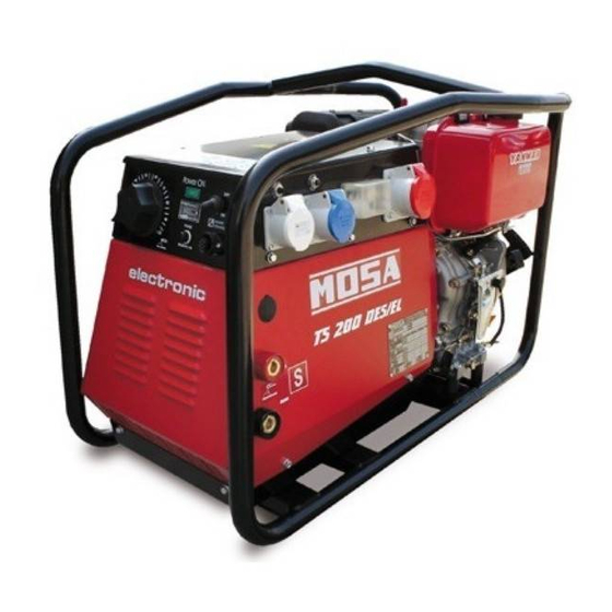
TS 200 DES/EL (STAGE V)
• Motosaldatrice
• Schweißaggregat
• Engine Driven Welder
• Motosoldadora
• Motosoudeuse
• По Вышкам
• Motosoldadoras
• Lassers
M A D E
I N
I T A L Y
language
Codice
Code
Code
Codigo
C0JP50609003
Kodezahl
Código
Код
Code
Edizione
Edition
Édition
Edición
06.2019
Ausgabe
Edição
Издание
Editie
Advertisement
Table of Contents

Related Manuals for MOSA Weld TS 200 DES/EL


Summary of Contents for MOSA Weld TS 200 DES/EL
- Page 1 USE AND MAINTENANCE MANUAL TRANSLATION OF THE ORIGINAL INSTRUCTIONS – ENGLISH Codice COMPACT WELDERS Code Code Codigo TS 200 DES/EL (STAGE V) C0JP50609003 Kodezahl Código Код Code Edizione Edition Édition • Motosaldatrice • Schweißaggregat Edición 06.2019 • Engine Driven Welder •...
-
Page 3: Table Of Contents
INDEX 0. GENERAL INFORMATION M1.1 INTRODUCTION ........................PAG. 4 CE MARK ..........................PAG. 5 M1.4.2 SYMBOLS AND SAFETY PRECAUTIONS ................... PAG. 6 WARNINGS ..........................PAG. 7 M2.1 M2.5... SAFETY RULES ........................PAG. 8 1. GENERAL INFORMATION OF THE MACHINE DESCRIPTION OF THE MACHINE....................PAG. 12 RECORDING DATA ........................ -
Page 4: Introduction
INTRODUCTION Dear Customer, The Manufacturer shall not be liable for ANY USE OF THE PRO- We wish to thank you for having bought a high quality set. DUCT OTHER THAN THAT PRECISELY SPECIFIED IN THIS Our sections for Technical Service and Spare Parts will work at MANUAL and is thus not liable for any risks which may occur as best to help you if it were necessary. -
Page 5: Ce Mark
CE MARKING ENGINE DRIVEN WELDER 1.4.2 Any of our product is labelled with CE marking attesting its conformity to appliable directives and also the fulfillment of safety requirements of the product itself; the list of these directives is part of the declaration of conformity included in any machine standard equipment. -
Page 6: Symbols And Safety Precautions
SYMBOLS AND SAFETY PRECAUTIONS SYMBOLS IN THIS MANUAL DANGER - The symbols used in this manual are designed to call your GENERAL ADVICE - If the advice is not respec- attention to important aspects of the operation of the machine ted damage can happen to persons or things. -
Page 7: Warnings
WARNINGS FIRST AID. In case the operator shold be sprayed by accident, from corrosive liquids a/o hot toxic gas or whate- ver event which may cause serious injuries or death, predispose the first aid in accordance with the ruling labour accident standards or of local instructions. -
Page 8: M2.5
SAFETY RULES ENGINE DRIVEN WELDERS GENERAL SAFETY INSTRUCTIONS • Do not replace the tires with types different from the original + NOTE: the information contained in this manual are ones. subject to change without notice. • Check that the brakes and the optical signaling of the trailer are working properly. - Page 9 SAFETY RULES ENGINE DRIVEN WELDERS 2.5.1 SAFETY PRECAUTIONS DURING INSTALLATION AND USE Do not instal equipments closed to heat source, to explosion or fire risk area. Always locate the machine on a flat and solid ground, so as to avoid tipping, slipping or falling during operation. Avoid using the machine on slopes greater than 10 degrees.
- Page 10 SAFETY RULES ENGINE DRIVEN WELDERS 2.5.2 SAFETY PRECAUTIONS DURING MAINTENANCE Make use of qualified personnel to carry out maintenance and troubleshooting It is mandatory to stop the engine before performing any main- tenance on the machine. Always use protective devices and suitable equipment. Do not touch the engine, the exhaust pipes and the muffler during operation or immediately after.
- Page 11 SAFETY RULES ENGINE DRIVEN WELDERS 2.5.3 ADDITIONAL REQUIREMENTS FOR ENGINE DRIVEN WELDERS Do not touch parts with OCV, it can cause mortal shock or heavy born. OCV is active at welding stick and auxiliary side when welding generating set is working. Do not manage electric devices and welding stick whit feet, hands or wet dresses.
-
Page 12: Description Of The Machine
DESCRIPTION OF THE MACHINE The TS 200 engine driven welder is a unit which ensures the function as: a) a current source for arc welding b) a current source for the auxiliary generation Unit meant for industrial and professional use, powered by an endothermic engine; it is composed of various main parts such as: engine, alternator, electric and electronic controls, the fairing or a protective structure. -
Page 13: Recording Data
RECORDING DATA The manual is for the range of machines indicated on the front cover. With the scope to facilitate the search of the spare parts and maintain information of the bought machine, is necessary to record some data. Please write the requested data inside the squares to side: Model of machine Serial number of the machine Serial number of the engine... -
Page 14: Machine Unpacking
MACHINE UNPACKING NOTE Be sure that the lifting devices are: correctly mounted, adequate for the weight of the machine with it’s packaging, and conforms to local rules and regulations. When receiving the goods make sure that the product has not suffered damage during the transport, that there has not been rough handling or taking away of parts contained inside the packing or in the set. -
Page 15: Transport And Handling Covered Units
TRANSPORT AND HANDLING COVERED UNITS ATTENTION Transportation must always take place with the engine off, electrical cables and starting battery disconnected and fuel tank empty. Be sure that the lifting devices are: correctly mounted, adequate for the weight of the machine with it’s packaging, and conform to local rules and regulations. - Page 16 INSTALLAZIONE - INSTALLATION - INSTALLATION INSTALACIÓN - LUFTZIRKULATION - INSTALAÇÃO УСТАНОВКА - INSTALLATIE...
-
Page 17: Installation
INSTALLATION AdvIceS eNGINe dRIveN WeLdeR INSTALLATION AND ADVICE BEFORE USE INSTALLATION Always instal the welder machine The operator of the welder is responsible for the security of the on a hard and plan surface in order people who work with the welder and for those in the vicinity. to avoid rollovers, slips or falls whi- le working;... -
Page 18: Electromagnetic Compatibility
ELECTROMAGNETIC COMPATIBILITY (EMC) ENGINE DRIVEN WELDERS This equipment is built in compliance with standard IEC- The size of the surrounding area to be considered will depend EN60974-10. on the structure of the building and other activities that are The equipment should be installed and used in accordance taking place. -
Page 19: Set-Up For Operation Diesel Engine
SET-UP FOR OPERATION (DIESEL ENGINE) AIR COOLED SYSTEMS BATTERY WITHOUT MAINTENANCE (WHERE IT IS ASSEMBLED) FUEL The supplied battery is generally ready for use. ATTENTION Connect the cable + (positive) to the pole + of the battery, by properly tightening the clamp. Stop engine when fueling. -
Page 20: Earthing
Earthing Earthing WithOUt grOUnD FaULt intErrUPtEr Earthing With isOmEtEr The protection against electric shock from contact indirect is Machines equipped with insulation resistance monitor allow intentionally not to connect the ground terminal PE (12) to an ensured by the “electrical separation” with equipotential bonding earthing system. -
Page 21: Starting And Stopping
STARTING AND STOPPING electRic stARtiNg 5) pull the rope hard and fast. Pull it all the way out. Use two hands if check daily necessary. NOte AtteNtiON Do not alter the primary conditions of regulation and do not If the battery is not connected, disconnect voltage regulator touch the sealed parts. -
Page 22: Controls Legende
CONTROLS LEGENDE Hydraulic oil level light Engine control unit EP2 Engine control unit EP6 Welding socket ( + ) E.A.S. connector Welding voltage voltmeter Welding socket ( - ) Exclusion indicating light PTO HI Polarity inverter control Earth terminal Auxiliary current push button Oil pressure indicator A.C. - Page 23 COMANDI - CONTROLS - COMMANDES - MANDOS - BEDIENELEMENTE - COMANDOS СИСТЕМЫ УПРАВЛЕНИЯ - BEDIENING...
-
Page 24: Controls
CONTROLS DESCRIPTION pos. description function c.c. welding sockets (+) Connection sockets for welding cables c.c. welding sockets (-) Connection sockets for welding cables Welding current regulator Allows the regulation of the welding current Remote control socket Multiple connector for remote control. Remote control switch In ON position it qualifies the remote control to regulate the welding current. -
Page 25: Use As Welder
USe AS weLDeR TS 200 DeS/eL - TS 200 BS/eL - TS 200 BS/eL-P ADJUsTING ThE WELDING cURRENT This symbol (Norm EN 60974-1 security standards for arc welders ) signifies that the welder can be used in areas with increased risk of electrical shock. -
Page 26: M37
UsE As gEnErAtor EngInE DrIVEn WELDErs VOLTAGE WARNING In some types of generators (asynchronous) the no-load vol- tage can be even higher than 10% with respect to its nominal value; for example, for nominal voltage, three-phase 400Vac It is absolutely forbidden to connect the unit to the public mains and/or another electrical power source . - Page 27 UsE As gEnErAtor EngInE DrIVEn WELDErs 37.1 ELECTRIC PROTECTIONS THERMIC PROTECTION Generally present to protect against overloads on an individual THERMAL-MAGNETIC SWITCH power socket c.a. When the nominal operating current has been exceeded, the + NOTE: for some types of alternators (asynchronous alter- protection device intervenes by cutting off power to the socket.
-
Page 28: Remote Control Tc2 / Tc2-50
REMOTE CONTROL TC2 / TC2/50 PUSH AND SCREW TIGHT The remote control device for regulating the welding current is connected to the front panel by means of a multipole connector. To regulate the current from the TC2 / TC2/50, move the switch (7), located above the multipole connector (8), to "ON"... -
Page 29: Engine Protection
ENGINE PROTECTION 39.6 The warning lamps brighten by turning the engine starting key (Q1) in ON position and they switch off a few seconds after engine running. The engine protection, in case of low oil pressure, is shown by the warning light (O1) without the engine stopping. -
Page 30: M55 Recommanded Electrodes
RECOMMENDED ELECTRODES (IN ACCORDANCE WITH A.W.S STANDARD) The information here below are to be intended only as indicative since the above norm is much larger. For further details please see the specific norms and/or the manufacturers of the product to be used in the welding process. RUTILE ELECTRODES: E 6013 Easily removable fluid slag, suitable foe welding in all position. -
Page 31: M40.2
Trouble shooTing 40.2 WARNING ● Have qualified personnel do maintenance and troubleshooting work. ● Stop the engine before doing any work inside the machine. If for any reason the machine must be operated while working inside, pay attention mo- ving parts, hot parts (exhaust manifold and muffler, etc.) electrical parts which may be unprotected when the machine is open. ●... - Page 32 TROUBLe SHOOTING 40.2.1 Problems Possibie cause Solution WELDING P1 No welding current but auxiliary 1) Position of remote control switch 1) Check that it is in OFF position if there is no remote control, on output is OK “ON” with remote control inserted. 2) Potentiometer defect in welding current 2) Check the continuity of the welding potentiometer and relative control...
-
Page 33: Maintenance
MAINTENANCE WARNING ● Have qualified personnel do maintenance and troubleshooting work. ● Stop the engine before doing any work inside the machine. If for any reason the machine must be operated while working inside, pay at- tention moving parts, hot parts (exhaust manifold and muffler, etc.) electrical parts which may be unprotected when the machine is open. -
Page 34: Maintenance Scheduled Yanmar
MAINTENANCE SCHEDULED YANMAR L100 IMPORTANT The engine and alternator manufacturers indicate specific maintenance and control intervals: it is obligatory to consult the books, OPERATION AND MAINTENANCE of the engine and alternator provided with the generator you are using. If such documents are not supplied with the generator set, ask for a copy to the customer service. The information given in the table is only indicative. -
Page 35: Storage And Disassemble
STORAGE And diSASSEmblE STORAGE DISASSEMBLE + Have qualified personnel disassemble the machine and In case the machine should not be used for more than 30 days, dispose of the parts, including the oil, fuel, etc., in a correct make sure that the room in which it is stored presents a suitable manner when it is to be taken out of service. -
Page 36: Technical Data
TECHNICAL DATA GENERATOR Three-phase generation 6 kVA / 400 V / 8.7 A Single-phase generation 5 kVA / 230 V / 21.7 A Single-phase generation 2.5 kVA / 110 V / 22.7 A Single-phase generation 2 kVA / 48 V / 41.6 A Frequency 50 Hz Cos ϕ... -
Page 37: Technical Data
TECHNICAL DATA C.C. WELDING Welding current regulation 20 - 170 A Service 170 A - 60%, 130 A - 100% Welding voltage OUtpUt cHARActeRistic siMUltANeOUs UtiliZAtiON fActORs In case WeldiNg and geNeRAtiON can be used simultaneously, however, the engine cannot be overloaded. The table below gives the maximum limits to be respected: WELDING >100 A... -
Page 38: M2.7.1 Dimensions
DIMENSIONI - DIMENSIONS - DIMENSIONS DIMENSIONES - ABMESSUNGEN - DIMENSÕES 2.7.1 РАЗМЕРЫ - AFMETINGEN... -
Page 39: Electrical System Legende
ELECTRICAL SYSTEM LEGENDE : Alternator E3 : Open circuit voltage switch I6 : Start Local/Remote selector N9 : UP/DOWN button mast : Wire connection unit F3 : Stop push-button L6 : Choke button O9 : Hydraulic unit solenoid valve C : Capacitor G3 : Ignition coil M6 : Switch CC/CV P9 : Hydraulic unit engine... -
Page 40: M61
SCHEMA ELETTRICO - ELECTRIC DIAGRAM - SCHEMA ELECTRIqUES - ESqUEMA ELÉCTRIqUE STROMLAUFPLAN - ESqUEMA ELÉTRICO - ЭЛЕКТРИЧЕСКАЯ СХЕМА - ELEKTRISCHE REGELING... - Page 41 SCHEMA ELETTRICO - ELECTRIC DIAGRAM - SCHEMA ELECTRIqUES - ESqUEMA ELÉCTRIqUE STROMLAUFPLAN - ESqUEMA ELÉTRICO - ЭЛЕКТРИЧЕСКАЯ СХЕМА - ELEKTRISCHE REGELING...
- Page 42 SCHEMA ELETTRICO - ELECTRIC DIAGRAM - SCHEMA ELECTRIqUES - ESqUEMA ELÉCTRIqUE STROMLAUFPLAN - ESqUEMA ELÉTRICO - ЭЛЕКТРИЧЕСКАЯ СХЕМА - ELEKTRISCHE REGELING...
- Page 43 SCHEMA ELETTRICO - ELECTRIC DIAGRAM - SCHEMA ELECTRIqUES - ESqUEMA ELÉCTRIqUE STROMLAUFPLAN - ESqUEMA ELÉTRICO - ЭЛЕКТРИЧЕСКАЯ СХЕМА - ELEKTRISCHE REGELING...
- Page 44 SCHEMA ELETTRICO - ELECTRIC DIAGRAM - SCHEMA ELECTRIqUES - ESqUEMA ELÉCTRIqUE STROMLAUFPLAN - ESqUEMA ELÉTRICO - ЭЛЕКТРИЧЕСКАЯ СХЕМА - ELEKTRISCHE REGELING...
- Page 45 NOTE...
- Page 46 NOTE...
- Page 48 MOSA div. della BCS S.p.A. Viale Europa, 59 20090 Cusago (Milano) Italy Tel.+39 - 0290352.1 Fax +39 - 0290390466 www.mosa.it...
Need help?
Do you have a question about the TS 200 DES/EL and is the answer not in the manual?
Questions and answers