Table of Contents
Advertisement
Quick Links
USE AND MAINTENANCE MANUAL
TRANSLATION OF THE ORIGINAL INSTRUCTIONS – ENGLISH
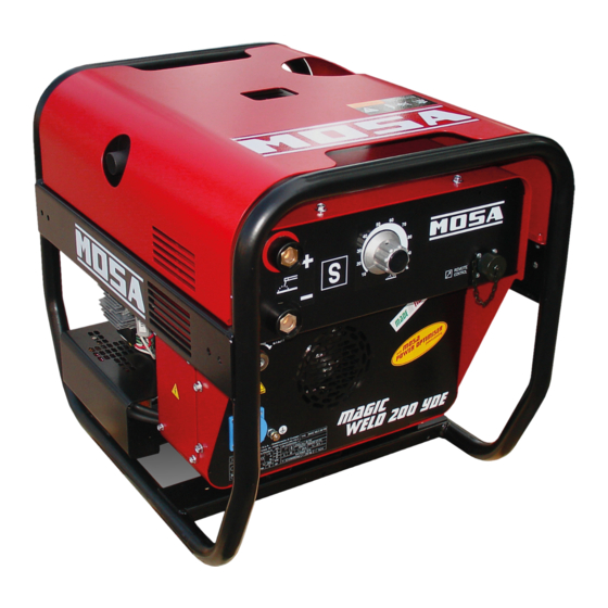
COMPACT WELDERS
MAGIC WELD 200 YDE (STAGE V)
• Motosaldatrice
• Schweißaggregat
• Engine Driven Welder
• Motosoldadora
• Motosoudeuse
• По Вышкам
• Motosoldadoras
M A D E
I N
I T A L Y
3
language
Codice
Code
Code
C0EP20009003
Codigo
Kodezahl
Código
Код
Edizione
Edition
Édition
Edición
10.2019
Ausgabe
Edição
Издание
Advertisement
Table of Contents

Related Manuals for MOSA Weld MAGIC WELD 200 YDE


Summary of Contents for MOSA Weld MAGIC WELD 200 YDE
- Page 1 USE AND MAINTENANCE MANUAL TRANSLATION OF THE ORIGINAL INSTRUCTIONS – ENGLISH Codice COMPACT WELDERS Code Code MAGIC WELD 200 YDE (STAGE V) C0EP20009003 Codigo Kodezahl Código Код Edizione Edition Édition • Motosaldatrice • Schweißaggregat Edición 10.2019 • Engine Driven Welder •...
-
Page 3: Table Of Contents
INDEX 0. GENERAL INFORMATION M1.1 INTRODUTION ........................PAG. 4 M1.4.2 CE MARK ........................... PAG. 5 SYMBOLS AND SAFETY PRECAUTIONS ................PAG. 6 M2.1 WARNINGS ........................PAG. 7 M2.5... SAFETY RULES (ENGINE DRIVEN WELDERS) ............... PAG. 8 GENERAL INFORMATION OF THE MACHINE DESCRIPTION OF THE MACHINE .................. -
Page 4: Introdution
INTRODUCTION Dear Customer, The Manufacturer shall not be liable for ANY USE OF THE PRO- We wish to thank you for having bought a high quality set. DUCT OTHER THAN THAT PRECISELY SPECIFIED IN THIS Our sections for Technical Service and Spare Parts will work at MANUAL and is thus not liable for any risks which may occur as best to help you if it were necessary. -
Page 5: M1.4.2 Ce Mark
CE MARKING ENGINE DRIVEN WELDER 1.4.2 Any of our product is labelled with CE marking attesting its conformity to appliable directives and also the fulfillment of safety requirements of the product itself; the list of these directives is part of the declaration of conformity included in any machine standard equipment. -
Page 6: Symbols And Safety Precautions
SYMBOLS AND SAFETY PRECAUTIONS SYMBOLS IN THIS MANUAL DANGER - The symbols used in this manual are designed to call your GENERAL ADVICE - If the advice is not respec- attention to important aspects of the operation of the machine ted damage can happen to persons or things. -
Page 7: Warnings
WARNINGS FIRST AID. In case the operator shold be sprayed by accident, from corrosive liquids a/o hot toxic gas or whate- ver event which may cause serious injuries or death, predispose the first aid in accordance with the ruling labour accident standards or of local instructions. -
Page 8: M2.5
SAFETY RULES ENGINE DRIVEN WELDERS GENERAL SAFETY INSTRUCTIONS • Do not replace the tires with types different from the original + NOTE: the information contained in this manual are ones. subject to change without notice. • Check that the brakes and the optical signaling of the trailer are working properly. - Page 9 SAFETY RULES ENGINE DRIVEN WELDERS 2.5.1 SAFETY PRECAUTIONS DURING INSTALLATION AND USE Do not instal equipments closed to heat source, to explosion or fire risk area. Always locate the machine on a flat and solid ground, so as to avoid tipping, slipping or falling during operation. Avoid using the machine on slopes greater than 10 degrees.
- Page 10 SAFETY RULES ENGINE DRIVEN WELDERS 2.5.2 SAFETY PRECAUTIONS DURING MAINTENANCE Make use of qualified personnel to carry out maintenance and troubleshooting It is mandatory to stop the engine before performing any main- tenance on the machine. Always use protective devices and suitable equipment. Do not touch the engine, the exhaust pipes and the muffler during operation or immediately after.
- Page 11 SAFETY RULES ENGINE DRIVEN WELDERS 2.5.3 ADDITIONAL REQUIREMENTS FOR ENGINE DRIVEN WELDERS Do not touch parts with OCV, it can cause mortal shock or heavy born. OCV is active at welding stick and auxiliary side when welding generating set is working. Do not manage electric devices and welding stick whit feet, hands or wet dresses.
-
Page 12: Description Of The Machine
DESCRIPTION OF THE MACHINE The MAGIC WELD engine driven welder is a unit which ensures the dual function as: a) a current source for are welding b) current generator for generating auxiliary Unit meant for industrial and professional use. Powered by an endothermic engine; it is composed of various parts such as: engine, alternator, electric and electronic controls, the fairing at a protective structure. -
Page 13: Recording Data
RECORDING DATA The manual is for the range of machines indicated on the front cover. With the scope to facilitate the search of the spare parts and maintain information of the bought machine, is necessary to record some data. Please write the requested data inside the squares to side: Model of machine Serial number of the machine Serial number of the engine... -
Page 14: Machine Unpacking
MACHINE UNPACKING NOTE Be sure that the lifting devices are: correctly mounted, adequate for the weight of the machine with it’s packaging, and conforms to local rules and regulations. When receiving the goods make sure that the product has not suffered damage during the transport, that there has not been rough handling or taking away of parts contained inside the packing or in the set. -
Page 15: Transport And Handling
TRANSPORT AND HANDLING COVERED UNITS ATTENTION Transportation must always take place with the engine off, electrical cables and starting battery disconnected and fuel tank empty. Be sure that the lifting devices are: correctly mounted, adequate for the weight of the machine with it’s packaging, and conform to local rules and regulations. -
Page 16: M2.7
IINSTALLAZIONE - INSTALLATION - INSTALLATION - LUFTZIRKULATION - INSTALACIÓN - INSTALAÇÃO M1.4... -
Page 17: Installation And Advice
INSTALLATION AdvIceS eNGINe dRIveN WeLdeR INSTALLATION AND ADVICE BEFORE USE INSTALLATION Always instal the welder machine The operator of the welder is responsible for the security of the on a hard and plan surface in order people who work with the welder and for those in the vicinity. to avoid rollovers, slips or falls whi- le working;... -
Page 18: Set-Up For Operation
SET-UP FOR OPERATION BATTERY WITHOUT MAINTENANCE FUEL (WHERE IT IS ASSEMBLED) The included battery must be activated. To activate it (fill the included acid) please follow the instructions ATTENTION shown on the manual attached to the battery. When battery is activated, DON’T add any other liquid. Stop engine when fueling. -
Page 19: Starting
STARTING ELECTRIC STARTING Check daily Carry out operations 1) and 5) as with pull start Turn the starter key to the “ON” position, the accelerator con- trol solenoid will automatically move the accelerator lever into the "START" position START NOTE Do not alter the primary conditions of regulation and Turn the starter key to the “START”... -
Page 20: Stopping
STOPPING + Before stopping the engine it is compulsory to stop the load: - stop welding; - shut off any loads which are connected to the unit auxiliary outputs. RECOIL VERSION Let the motor run at no load for several minutes to allow for cooling and then move the accele- rator control into the “STOP”... -
Page 21: M31 Controls
COMANDI - CONTROLS - COMMANDES - MANDOS - BEDIENELEMENTE - COMANDOS СИСТЕМЫ УПРАВЛЕНИЯ - BEDIENING O1 Q1 SCHUKO vers. POS. DESCRIZIONE DESCRIPTION DESCRIPTION REFERENZLISTE Prese di saldatura (+) Welding sockets (+) Prises de soudage (+) Schweißbuchse ( + ) Prese di saldatura (-) Welding sockets (-) Prises de soudage (-) Schweißbuchse ( - ) -
Page 22: M34
USE AS WELDER This symbol (Norm EN 60974-1 security standards for arc welders) signifes that the welders can be used in areas with increa-sed risk of electrical shock. ATTENTION It is prohibited for any unauthorized persons to access areas adjacent to the engine driven welder or the welding process. -
Page 23: Use As Generator
USE AS A GENERATOR ATTENTION It is absolutely forbidden to connect the unit to the public mains and/or another electrical power source. ATTENTION It is prohibited for any unauthorized persons to access areas adjacent to engine driven welder. AUXILIARY GENERATION IN AC 230V/50Hz The auxiliary output is drawn by means of a 3 pole socket, the two poles are live, phase and neutral, plus the earth for the machine. -
Page 24: Engine Protection
ENGINE PROTECTIONS 39.6 The engine is equipped with system protection (stop) in the event the oil pressure is too low. In the event of a malfunction in the battery charging system, the warning light will come on without stopping the engine. -
Page 25: Raccomanded Electrodes
RECOMMENDED ELECTRODES (IN ACCORDANCE WITH A.W.S STANDARD) The information here below are to be intended only as indicative since the above norm is much larger. For further details please see the specific norms and/or the manufacturers of the product to be used in the welding process. RUTILE ELECTRODES: E 6013 Easily removable fluid slag, suitable foe welding in all position. -
Page 26: M40.2
TROUBLE-SHOOTING 40.2 Problem Possible cause Solution ENGINE The motor does not start up, 1) Lack of fuel in tank 1) Refill tank or starts up and then stops 2) Air in the fuel circuit 2) Check power supply circuit immediately 3) Incorrect position of accelerator control 3) Check position knob... - Page 27 TROUBLE-SHOOTING 40.2.1 Problem Possible cause Solution WELDING CIRCUIT No current under no-load 1) Faulty welding control board 1) With a voltmeter check that between pins conditions in weld mode A (-) and B (+) of the circular connector on the front panel there is 5 Vdc. Ask for intervention of Service De- partment to replace the board.
-
Page 28: Maintenance
MAINTENANCE WARNING ● Have qualified personnel do maintenance and troubleshooting work. ● Stop the engine before doing any work inside the machine. If for any reason the machine must be operated while working inside, pay at- tention moving parts, hot parts (exhaust manifold and muffler, etc.) electrical parts which may be unprotected when the machine is open. -
Page 29: M45 Storage And Cast Off
STORAGE And diSASSEmblE STORAGE DISASSEMBLE + Have qualified personnel disassemble the machine and In case the machine should not be used for more than 30 days, dispose of the parts, including the oil, fuel, etc., in a correct make sure that the room in which it is stored presents a suitable manner when it is to be taken out of service. -
Page 30: Technical Data
TECHNICAL DATA A.C. GENERATION 50/60 Hz MAGIC WELD 200 YDE Single-phase output 230V (max) 3.3 kVA / 230 V / 14.3 A Single-phase output 230V (continuous) 3 kVA / 230 V / 13 A Single-phase output 115V (max) 2.1 kVA / 110 V / 18.3A Single-phase output 115V (continuous) 1.8 kVA / 110 V / 16.4 A... -
Page 31: Technical Data (Welding)
TECHNICAL DATA D.C. WELDING MAGIC WELD 200 Y Current range, continuous 20 - 200A Open circuit voltage Duty cycle 200 A - 60% OUTPUT CARACTERISTIC SIMULTANEOUS UTILIZATION FACTORS In case Welding and Generation can be used simultaneously, however, the engine cannot be overloaded. The table below gives the maximum limits to be respected. -
Page 32: M2.7.1 Dimensions
DIMENSIONI - DIMENSIONS - DIMENSIONS - ABMESSUNGEN - DIMENSIONES - DIMENSÕES 2.7.1 1245 243.5... - Page 33 NOTE...
- Page 34 NOTE...
- Page 36 MOSA div. della BCS S.p.A. Viale Europa, 59 20090 Cusago (Milano) Italy Tel.+39 - 0290352.1 Fax +39 - 0290390466 www.mosa.it...
Need help?
Do you have a question about the MAGIC WELD 200 YDE and is the answer not in the manual?
Questions and answers