Table of Contents
Advertisement
Quick Links
USE AND MAINTENANCE MANUAL
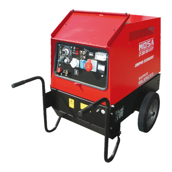
CT 230 YSX CC/CV
• Motosaldatrice
• Schweißaggregat
• Engine Driven Welder
• Motosoldadora
• Motosoudeuse
• По Вышкам
• Motosoldadoras
M A D E
I N
I T A L Y
Codice
Code
Code
372999003
Codigo
Kodezahl
Código
Код
Edizione
Edition
Édition
Edición
11.2013
Ausgabe
Edição
Издание
Advertisement
Table of Contents

Related Manuals for MOSA Weld CT 230 YSX CC/CV


Summary of Contents for MOSA Weld CT 230 YSX CC/CV
- Page 1 USE AND MAINTENANCE MANUAL Codice CT 230 YSX CC/CV Code Code 372999003 Codigo Kodezahl Código Код Edizione Edition Édition • Motosaldatrice • Schweißaggregat Edición 11.2013 • Engine Driven Welder • Motosoldadora Ausgabe • Motosoudeuse • По Вышкам Edição • Motosoldadoras Издание M A D E...
-
Page 3: Description Of The Machine
DESCRIPTION OF THE MACHINE CT 230 YSX CC/CV REV.1-11/13 Main characteristics of the unit: • Multi process welder: - SMAW: Shielder Metal Arc Welding (Stick) - GMAW: Gas Metal Arc Welding (MIG) • Control of current with CHOPPER technology at high frequency • Check the maximum engine power • Maximum welding current 210A/20V • Arc force for cellulosic electrodes • 6 kVA of power in three-phase generation 400 V / 50 Hz (Schuko version) • 5 kVA of power in single-phase generation 230 V / 50 Hz • Yanmar Diesel engine L 100 N more silenced • Tank of 23l with autonomy of 23 h • Noise level at 7m 67dBA • Dimensions / weight: 1020x645x930 / 230 Kg BATTERY FILTER... - Page 5 Index CT 230 YSX CC/CV REV.1-11/13 M 0 DESCRIPTION OF THE MACHINE M 1.01 COPYRIGHT M 1.1 NOTES M 1.4 CE MARK M 1.5 TECHNICAL DATA M 2 ADVICE M 2.1 SYMBOLS AND SAFETY PRECAUTIONS M 2.5.1 ADVICE (ENGINE DRIVEN WELDER) M 2.6 INSTALLATION AND ADVICE M 2.7 INSTALLATION M 2.7.1 DIMENSIONS M 3 UNPACKING M 4.1 TRANSPORT AND DISPLACEMENTS M 6.9 ASSEMBLY: CTM 2 M 20 SET-UP FOR OPERATION M 21 STARTING AND STOPPING THE ENGINE M 30 CONTROLS LEGEND...
- Page 6 Copyright 1.01 REV.0-10/02 ATTENTION This use and maintenance manual is an important part of the machines in question. The assistance and maintenance personel must keep said manual at disposal, as well as that for the engine and alternator (if the machine is synchronous) and all other documentation about the machine.
-
Page 7: Notes About The Manual
Notes REV.1-03/14 INFORMATION INFORMATION OF GENERAL TYPE In the envelope given together with the machine and/or Dear Customer, set you will find: the manual for Use Maintenance and We wish to thank you for having bought a high quality set. Spare Parts, the manual for use of the engine and the tools (if included in the equipment), the guarantee (in the Our sections for Technical Service and Spare Parts will... - Page 8 CE MARKING REV.7-02/14 Any of our product is labelled with CE marking attesting its conformity to appliable directives and also the fulfillment of safety requirements of the product itself; the list of these directives is part of the declaration of conformity included in any machine standard equipment. Here below the adopted symbol: CE marking is clearly readable and unerasable and it can be either part of the data-plate.
- Page 9 Technical data CT 230 YSX CC/CV REV.1-11/13 The CT 230 engine driven welder ia a unit which ensures the function as: a) a current source for arc welding b) a current source for the auxiliary power generation It is meant for industrial and professional use, powered by an endothermic engine; it is composed of various main parts such as: engine, alternator, electric and electronic controls, the fairing or a protective structure. The assembling is made on a steel structure, on which are provided elastic support which must damp the vibrations and also eliminate sounds which would produce noise. Technical data CT 230 YSX CC/CV GENERATOR Three-phase power 6 kVA / 400 V / 8.7 A Single-phase power 5 kVA / 230 V / 21.7 A Single-phase power 2.5 kVA / 110 V / 22.7 A Frequency 50 Hz ALTERNATOR self-excited, self-regulated, brushless Type three-phase, asynchronous Insulating class ENGINE Mark / Model...
- Page 10 Technical data CT 230 YSX CC/CV REV.0-12/08 D.C. WELDING Duty cycle 210A - 60%, 180 A - 100% Welding current electronic regulation 20 - 210 A Open circuit voltage C.V. WELDING Welding current 210 A - 60%, 180 A - 100% Welding voltage 15 - 30V STATIC CHARACTERISTIC C.C. C.V. min. increasing arc force SIMULTANEOUS UTILIZATION FACTORS In case Welding and Generation can be used simultaneously, however, the engine cannot be overloaded. The table below gives...
- Page 11 WARNINGS REV.1-02/14 The installation and general warnings regarding operations are aimed achieving correct use of the machine and/or apparatus in the place where it is used as a genset and/or motor welder. - Advice to the User about the safety: + NB: The information contained in the manual can be changed without notice.
-
Page 12: Symbols And Safety Precautions
SYMBOLS AND SAFETY PRECAUTIONS REV.2-06/10 SYMBOLS PROHIBITIONS No harm for persons Use only with safety clothing - STOP - Read absolutely and be duly attentive It is compulsory to use the personal protection means given in equip- ment. Use only with safety clothing - Read and pay due attention It is compulsory to use the personal protection means given in equipment. - Page 13 PRECAUTION (ENGINE DRIVEN WELDER) 2-5- REV.0-03/00 INSTALLATION AND ADVICE BEFORE USE The operator of the welder is responsible for the security of the people who work with the welder and for those in the vicinity. The security measures must satisfy the rules and regulations for engine driven welders. The information given below is in addition to the local security norms.
-
Page 14: Gasoline Engines
INSTALLATION AND ADVICE REV.1-06/07 Check that the air gets changed completely and the hot INSTALLATION AND ADVICE BEFORE USE air sent out does not come back inside the set so as to cause a dangerous increase of the temperature. GASOLINE ENGINES Use in open space, air swept or vent exhaust gases, which contain the deathly carbone oxyde, far from the work area. - Page 15 Installazione Luftzirkulation Installation Instalación CT 230 SX Installation CT 230 YSX CC/CV REV.1-12/07...
- Page 16 Dimensioni Dimensions Dimensiones CT 230 SX 2.7.1 Dimensions CT 230 YSX CC/CV REV.0-04/05 1048 Ø 14 n°2 fori Ø n°2 fori 1410...
- Page 17 UNPACKING REV.1-02/04 NOTE + Be sure that the lifting devices are: correctly mounted, adequate for the weight of the machine with it’s pack- aging, and conforms to local rules and regulations. When receiving the goods make sure that the product has not suffered damage during the transport, that there has not been rough handling or taking away of parts contained inside the packing or in the set.
- Page 18 TRANSPORT AND DISPLACEMENTS COVERED UNITS REV.2-09/11 NOTE Transportation must always take place with the engine off, electrical cables and starting battery disconnected and fuel tank empty. Be sure that the lifting devices are: correctly mounted, adequate for the weight of the machine with it’s packaging, and conform to local rules and regulations.
- Page 19 CTM2 ASSEMBLY REV.0-06/00 ATTENTION The CTM accessory cannot be removed from the machine and used separately (actioned manually or following vehicles) for the transport of loads or anyway for used different from the machine movements. Note: Lift the machine and assemble the parts as shown in the drawing...
-
Page 20: Grounding Connection
Set-up for operation (Engine diesel) Air cooled systems REV.1-09/05 OIL BATH AIR FILTER BATTERY WITHOUT MAINTENANCE Connect the cable + (positive) Fill the air filter using the same engine oil up to the to the pole + (positive) of the level indicated on the filter. -
Page 21: Stopping The Engine
ENGINE STARTING - STOPPING THE ENGINE CT 230 SX CT 230 YSX CC/CV REV.1-11/13 Check daily STOPPING THE ENGINE Before stopping the engine it is compulsory to effect the following operations: NOTE Do not alter the primary conditions of regulation and do not touch the sealed parts. STARTING THE ENGINE... - Page 22 CONTROLS LEGENDE REV.3-04/13 Hydraulic oil level light Exclusion indicating light PTO HI Selection push button 30 l/1' PTO HI Welding socket ( + ) Auxiliary current push button Battery voltmeter Welding socket ( - ) Fuel level light Remote control socket Earth terminal E.A.S. PCB Button indicating light 20 l/1' PTO HI A.C. socket Control unit for generating sets QEA Commutator/switch, serial/parallel Accelerator lever Thermal-magnetic circuit breaker Ground fault interrupter ( 30 mA ) Feed pump Selection push button 20 l/1' PTO HI Engine control unit and economiser 48V D.C. socket Water temperature indicator Engine air filter Ammeter Oil level dipstick Frequency meter Engine oil reservoir cap Frequency rpm regulator 24A Hydraulic oil reservoir cap Voltmeter regulator 24B Water filling cap Fuse Fuel prefilter Stop switch Fuel tank cap Warning light, high temperature Muffler...
- Page 23 Comandi Bedienelemente Controls Mandos CT 230 YSX CC/CV Commandes REV.0-11/14 230V 110V version N1 M1 Schuko version...
- Page 24 Operating CT 230 YSX CC/CV REV.0-12/08 After having prepared the machine (put in oil and fuel) the PUSH AND machine is ready for operation. SCREW TIGHT Before starting the engine please note the following: • The welder should only be operated by qualified personnel with experience in working with engine driven welders. welding cable welding sockets connector • Check the oil level daily. Fuel should be put in before starting the engine. Auxiliary power outlets • Before using the welder or the auxiliary power let the engine The unit is equipped with auxiliary output sockets. The volta- warm up and before stopping the engine let it run without load ges depend on the version selected. The three-phase socket,...
- Page 25 USE AS WELDER CT 230 YSX CC/CV REV.0-12/08 This symbol (Norm EN 60974-1 security stan- ATTENTION dards for arc welders) signifies that the welder can be used in areas with increased risk of To reduce the risk of electromagnetic interferences, use electrical shock. the minimum lenght of welding cables and keep them near and down (ex. on the floor). ATTENTION The welding operations must take place far from any sensitive electronic device. Make sure that the unit is earthed (see M20). In case the interference should last, The areas, access of which is forbiden to unqualified adapt further disposition,such as: move the unit, use personel, are: screened cables, line filters, screen the entire work area. - the control switchboard (front) - the exhaust of the In case the above mentioned operations are non suffici- engine - the welding process.
-
Page 26: Ground Fault Interrupter (Gfi)
USE AS A GENERATOR CT 230 YSX CC/CV REV.0-12/08 THERMAL CIRCUIT BREAKER (TBC) It is strictly forbidden to connect the group to CIRCUIT BREAKER (BC) the public mains a/o to another source of electric power. If you overload the generator the TBCs or BCs will au- tomatically switch off. WARNING lf the protection is released, disconnect all the connected loads. -
Page 27: Accessory Use
ACCESSORY USE REMOTE CONTROL TC2 / TC2/50 REV.1-06/05 PUSH AND SCREW TIGHT The remote control device for regulating the welding current is connected to the front panel by means of a multipole connector. To regulate the current from the TC2 / TC2/50, move the switch (7), located above the multipole connector (8), to "ON"... - Page 28 USE OF THE PROTECTION ENGINE PROTECTION 39.4 ES - EV REV..1-04/03 ENGINE PROTECTION (ES - EV) The devices ES or EV ensure the protection of the engine in case of low oil pressure or engine high temperature. The system consist of electronic card of control High temperature and check, and of an engine stop device: solenoid (ElettroStop), electrovalve (ElettroValvola)
- Page 29 40.1 Trouble shooting REV.0-02/11...
- Page 30 40.2 Trouble shooting REV.0-02/11...
- Page 31 40.3 Trouble shooting REV.0-02/11...
- Page 32 MAINTENANCE REV.1-01/13 WARNING ● Have qualified personnel do maintenance and troubleshooting work. ● Stop the engine before doing any work inside the machine. If for any reason the machine must be operated while working inside, pay at- tention moving parts, hot parts (exhaust manifold and muffler, etc.) electrical parts which may be unprotected when the machine is open.
-
Page 33: Gasoline Engine
STORAGE REV.0-06/07 In case the machine should not be used for more than 30 days, make sure that the room in which it is stored presents a suitable shelter from heat sources, weather changes or anything which can cause rust, corrosion or damages to the machine. - Page 34 CUST OFF REV.0-06/07 Have qualified personnel disassemble the In case of necessity for first aid and fire prevention, machine and dispose of the parts, including the see page M2.5. oil, fuel, etc., in a correct manner when it is to be taken out of service.
-
Page 35: Recommended Electrodes
RECOMMENDED ELECTRODES (In accordance with A.W.S Standard) REV.0-10/03 The information here below are to be intended only as indicative since the above norm is much larger. For further details please see the specific norms and/or the manufacturers of the product to be used in the welding process. - Page 36 ELECTRICAL SYSTEM LEGENDE REV.11-06/14 A : Alternator E3 : Open circuit voltage switch I6 : Start Local/Remote selector N9 : UP/DOWN button mast B : Wire connection unit F3 : Stop push-button L6 : Choke button O9 : Hydraulic unit solenoid valve C : Capacitor G3 : Ignition coil M6 : Switch CC/CV P9 : Hydraulic unit engine D : G.F.I. H3 : Spark plug N6 : Connector – wire feeder Q9 : Ignitor E : Welding PCB transformer I3 : Range switch O6 : 420V/110V 3-phase transformer...
- Page 37 Schema elettrico Electric diagram CT 230 SX 61.1 Schemas electriques CT 230 YSX CC/CV REV.0-04/05...
- Page 38 Schema elettrico Stromlaufplan Electric diagram Esquema eléctrique CT 230 YSX CC/CV 61.2 Schemas electriques REV.0-12/08...
- Page 39 Schema elettrico Electric diagram CT 230 SX 61.3 Schemas electriques REV.0-04/05...
- Page 40 Schema elettrico Stromlaufplan Electric diagram Esquema eléctrique CT 230 YSX CC/CV 61.4 Schemas electriques 230M/110Mx2 REV.0-11/13...
- Page 41 Schema elettrico Stromlaufplan Electric diagram Esquema eléctrique CT 230 YSX CC/CV 61.5 Schemas electriques 400T/230Mx2 REV.1-11/13...
- Page 44 MOSA div. della BCS S.p.A. Viale Europa, 59 20090 Cusago (Milano) Italy Tel.+39 - 0290352.1 Fax +39 - 0290390466 www.mosa.it...
Need help?
Do you have a question about the CT 230 YSX CC/CV and is the answer not in the manual?
Questions and answers