Table of Contents
Advertisement
Quick Links
Advertisement
Table of Contents

Subscribe to Our Youtube Channel
Related Manuals for TRENDnet TV-VS1


Summary of Contents for TRENDnet TV-VS1
-
Page 2: P Reface
REFACE Thank you for purchasing the TV-VS1/TV-VS1P Video Encoder, a standalone system that can easily connect the analog camera to your network. With support for latest H.264 technology, you can use the analog camera to record high-quality digital streaming video to your hard drive, enable motion detection and setup automated e-mail alerts for security. - Page 3 This Advanced Installation Guide provides you with the instructions and illustrations on how to use your Video Encoder, which includes: Chapter 1 Knowing Your Video Encoder describes the component features of the device, as well as the applications of the device.
-
Page 4: Table Of Contents
Contents ............... 1 R E F A C E 1 ..............5 H A P T E R ......... 5 N O W I N G O U R I D E O N C O D E R 1.1 C .......... - Page 5 How to ac c es s th e Vid eo E n cod er b eh in d a Rou t e r ..69 Ap p en d i x ..............75 A.1 S ................ 75 PECIFICATION A.2 GPIO T ..........
-
Page 6: Chapter 1
NOWING IDEO NCODER 1.1 Checking the Package Contents Check the items contained in the package carefully. You should have the following: TV-VS1 or TV-VS1P Multi-Language Quick Installation Guide CD-ROM (Utility & User’s Guide) GPIO Connector ... -
Page 7: Component Features
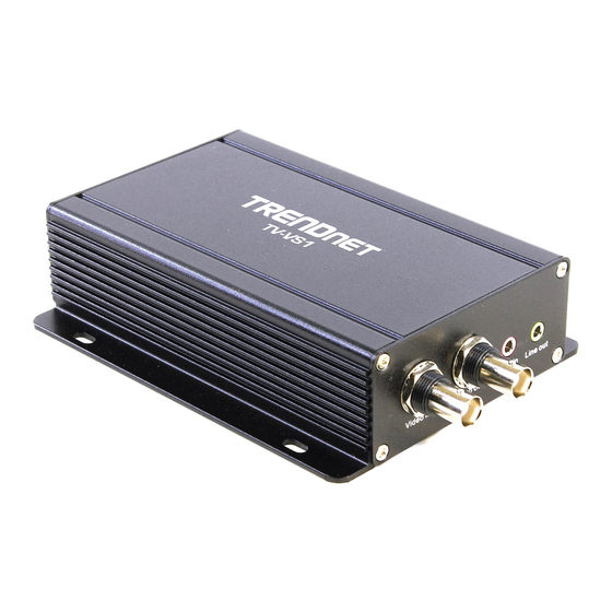
1.2 Component Features Front Panel Item Function Video In Connect an analog camera with the composite video output (BNC type). Video Out Connect an external video device with the composite video input (BNC type) to display the camera’s image on a conventional monitor. -
Page 8: Rear Panel
Rear Panel Item Function DC Power Connect one end of power plug into the power source Connector and the other end to the device. Power LED (upper) will light a steady amber light to indicate the device is powered on. -
Page 9: Features And Benefits
1.3 Features and Benefits H.264/MPEG4/MJPEG Multi-codec Supported The device provides you with excellent images by the H.264/MPEG4/ MJPEG multi-codec selectable technology, allowing you to adjust image size and quality, and bit rate according to the networking environment. Flexible Audio Capability The device allows you to connect the external microphone to receive on-the-spot audio via the Internet, allowing you to monitor the on-site voice. - Page 10 Remote Control Supported By using a standard Web browser, the administrator can easily change the configuration of the device via Intranet or Internet. In addition, the device can be upgraded remotely when a new firmware is available. The users are also allowed to monitor the image and take snapshots via the network.
-
Page 11: System Requirement
1.4 System Requirement Networking 10Base-T Ethernet or 100Base-TX Fast Ethernet; Auto-MDIX IEEE 802.3af PoE (TV-VS1P only) Accessing the Device using Web Browser Platform Microsoft® Windows® 7/Vista/XP CPU Intel Pentium III 800MHz or above RAM 512MB ... -
Page 12: Chapter 2
HAPTER ARDWARE NSTALLATION 2.1 Mounting the Device on the Wall The provided mounting Kit is used to mount the device on the wall or ceiling. The example below is wall mounting installation. You can place the device flexibly according to your need. a. -
Page 13: Connecting The Cables
2.2 Connecting the Cables 1. Connecting the device to power source Use the provided power adapter to connect the device to the power source, such as the electrical outlet on the wall, and connect the other end to the device. You can verify the power status from the Power LED on the rear panel of the device. -
Page 14: Applications Of The Video Encoder
2.3 Applications of the Video Encoder The video encoder can be applied in multiple applications, including: Monitor local and remote places and objects via Internet or Intranet. Capture still images and video clips remotely. Upload images or send email messages with the still images attached. -
Page 15: Chapter 3
HAPTER CCESSING IDEO NCODER 3.1 Using IP Setup The camera comes with a conveniently utility, IP Setup, which is included in the Installation CD-ROM, allowing you to search the camera on your network easily. 1. Insert the Installation CD-ROM into your computer’s CD-ROM drive to initiate the Auto-Run program. - Page 16 2. Click Install to install the IPSetup. 3. Click Finish to finish the installation. - 15 -...
- Page 17 4. After installing the IPSetup utility, the application is automatically installed to your computer, and creates a folder in “Start \Program\TRENDnet\IPSetup”. 5. Click Start > Programs > TRENDnet > IPSetup, and then click IPSetup 6. The IPSetup window will appear. It will search the Camera within the same network.
- Page 18 Camera Display Area: It shows the connected camera(s) within the same network. By default, the IP setting on the Camera is set up DHCP. If you have DHCP server, the camera will automatic get the IP address from DHCP server. If you do not have DHCP server on your network, it will show the default IP as 192.168.10.30.
-
Page 19: Accessing To The Device
3.2 Accessing to the device Whenever you want to access the device: 1. Since the default configuration of the Video Encoder is DHCP mode enabled, you are recommended to launch IPSetup to search the IP address that is assigned to the device by the DHCP server, and then click Link to access the device via the Web browser. - Page 20 After you login into the Web Configuration of the device, the Main screen will appear as below: The Main screen of the Web Configuration provides you with many useful information and functions, including: Live View/Setup Switch: ...
- Page 21 Snapshot allows you to capture and save a still image. Browse allows you to assign the destination folder to store the video clips and still images. Talk allows you to speak out through the connected camera. Please note only one user is allowed to use this function at a time.
-
Page 22: Configuring The Ip Address Of The Computer
3.3 Configuring the IP Address of the Computer If you are failed to access to the Video Encoder, please check the IP address of your computer. When you connect the device to your computer directly to proceed with configuration of the device, you need to set up the IP addresses to be in the same segment for the two devices to communicate. -
Page 23: Chapter 4
HAPTER ONFIGURING IDEO NCODER 4.1 Using the Web Configuration You can access and manage the Video Encoder through the Web browser. This chapter describes the Web Configuration, and guides you through the configuration of the device by using the Web browser. To configure the device, click on the Main screen of Web Configuration. -
Page 24: Using Smart Wizard
4.2 Using Smart Wizard The device’s Smart Wizard lets you configure your device easily and quickly. The wizard will guide you through the necessary settings with detailed instructions on each step. To start the wizard, click Smart Wizard in the left menu bar. Step 1. - Page 25 Step 2. IP Settings Setup the IP setting, DHCP, Static IP or PPPoE. Step 3. Email Settings Enter the mail server information. If you are using a free mails server, select the SSL and/or STARTTLS according to the mail server requirement. - 24 -...
- Page 26 Step 4. Confirm Settings - 25 -...
-
Page 27: Basic Setup
4.3 Basic Setup The Basic menu contains three sub-menus that provide the system settings for the device, such as the Server Name, Location, Date & Time, and User management. - 26 -... - Page 28 4.3.1 Basic >> System Basic: This item allows you to assign the device name and location information. Server Name: Enter a descriptive name for the Video Encoder, which is helpful to identify the device easily while multiple devices are connected within the network. Location: Enter a descriptive name for the location where is monitored by the connected camera.
- Page 29 4.3.2 Basic >> Date & Time Date and Time: Enter the correct date and time for the system. TimeZone: Select the proper time zone for the region from the pull-down menu. Synchronize with PC: Select this option and the date & time settings of the device will be synchronized with the connected computer.
- Page 30 4.3.3 Basic >> User Administrator: To prevent unauthorized access to the device’s Web Configuration, you are strongly recommend to change the default administrator password. Type the administrator password twice to set and confirm the password. General User User Name: Enter the user’s name you want to add to use the device.
- Page 31 Password: Enter the password for the new guest. UserList: Display the existing guests of the device. To delete a user, select the one you want to delete and click Delete. NOTE The “General User” can access the device and control the Function buttons of the device’s Web Configuration;...
-
Page 32: Network Settings
4.4 Network Settings The Network menu contains two sub-menus that provide the network settings for the device, such as the IP Setting, DDNS Setting, and IP Filter. - 31 -... - Page 33 4.4.1 Network >> Network IP Setting: This item allows you to select the IP address mode and set up the related configuration. The default setting is DHCP mode enabled. DHCP: Select this option when your network uses the DHCP server.
- Page 34 Enter the IP address of the device. The default setting is 192.168.10.30. Subnet Mask Enter the Subnet Mask of the device. The default setting is 255.255.255.0. Default Enter the Default Gateway of the device. The Gateway default setting is 192.168.10.1. Primary/ DNS (Domain Name System) translates domain Secondary DNS...
- Page 35 Ports Number HTTP Port: The default HTTP port is 80. NOTE If the device is behind an NAT router of firewall, the suggested to be used is from 1024 to 65535. 4.4.2 Network >> Network >> Advanced HTTPS Enable: Select this option to enable HTTPS, which is a secure protocol to provide authenticated and encrypted communication within your network.
- Page 36 HTTPS Port: Assign a HTTPS port in the text box. The default HTTPS port is 443. Bonjour: The devices with Bonjour will automatically broadcast their own services and listen for services being offered for the use of others. If your browser with Bonjour, you can find the device on your local network without knowing its IP address.
- Page 37 4.4.3 Network >> IP Filter The IP Filter setting allows the administrator of the device to limit the users within a certain range of IP addresses to access the device. To disable this feature, select the Disable option; otherwise, select the Accept option to assign the range of IP addresses that are allowed to access the device, or select the Deny option to assign the range of IP addresses that are blocked to access the device.
- Page 38 Deny IPv4: Assign a range of IP addresses that are blocked to access the device by entering the Start IP address and End IP address options. When you are finished, click Add to save the range setting. You can repeat the action to assign multiple ranges for the device.
-
Page 39: Setting Up Video & Audio
4.5 Setting up Video & Audio The Video & Audio menu contains four sub-menus that provide the video and audio settings for the device. - 38 -... - Page 40 4.5.1 Video & Audio >> Image Setting Image Setting Brightness: Adjust the brightness level from 0 ~ 100. Saturation: Adjust the colors level from 0 ~ 100. Sharpness: Adjust the sharpness level from 0 ~ 100. Hue: Adjust the hue level from 0 ~ 100. WDRC: Adjust value of WDRC (Wide Dynamic Range Correction) to provide clear images even when the background light varies excessively.
- Page 41 4.5.2 Video & Audio >> Video H.264 Video Resolution: Select the desired video resolution from the pull-down menu. Please note that higher setting obtains better video quality while it uses more resource within your network. Video Quality: Select the desired image quality from five levels: Lowest, Low, Medium, High, and Highest.
- Page 42 Video Quality: Select the desired image quality from five levels: Lowest, Low, Medium, High, and Highest. Frame Rate: Select a proper setting depending on your network status. MJPEG Video Resolution: Select the desired video resolution from the three formats: VGA, QVGA and QQVGA. The higher setting (VGA) obtains better video quality while it uses more resource within your network.
- Page 43 4.5.3 Video & Audio >> Audio Line In: Select the Enable option to enable the device’s audio function, so that you can receive the on-site sound and voice from the connected camera. Line Out: Select the Enable option to enable the device’s external speaker function, so that the connected speaker can play the sound and voice through the connected camera.
- Page 44 4.5.4 Video & Audio >> Overlay / Mask This sub-menu is used to set the image overlay and mask feature of the device. Image Overlay: This item allows you to set the image overlay. In the Image File option, click Browse to select the image file from your computer, and then click Upload.
- Page 45 NOTE The width and height of the input overlay graphic should be multiple of 4 at a maximum size of 38400 pixels each, and in JPG or BMP (24- bit RGB) format. Privacy Mask: This item allows you to configure up to two mask areas.
-
Page 46: Event Server Configuration
4.6 Event Server Configuration The Event Server menu contains four sub-menus that allow you to upload images to FTP, send emails that include still images, store the images to a NAS system, and send instant message When you complete the required settings (such as FTP server configuration), click Test to test the related configuration is correct or not. - Page 47 4.6.1 Event Server Setting >> HTTP HTTP Notify For Motion Trigger Send the query parameter via an HTTP notification when an event is triggered. Host: Enter the IP of the HTTP server Port: Enter the Port number of the HTTP server User Name: Enter the username of the HTTP server - 46 -...
- Page 48 Password: Enter the password of the HTTP server Query: Enter the query parameter for the request if necessary Example: Host: 192.168.10.1 Port: 80 Query: xxx.cgi?name1=value1&name2=value2 Ex: cgi/event.cgi?status=#s&time=#t&model=modelname Result: http://192.168.10.1:80/cgi/event.cgi?status=#s&time=#t&model= modelname 4.6.2 Event Server Setting >> FTP Host Address: Enter the IP address of the target FTP server. Port Number: Enter the port number used for the FTP server.
- Page 49 Directory Path: Enter the destination folder for uploading the images. For example, test. Passive Mode: Select the Enable option to enable passive mode. FTP Upload with: Select upload to FTP with one snapshot image or a series image in pre-event/post-event time when event triggered.
- Page 50 Google Gmail®, Yahoo®, Hotmail®), please enter the SMTP server address from the service provider. Sender Email Address: Enter the email address of the user who will send the email. For example, John@mymail.com. SMTP Port: Assign the SMTP port in the text box. The default SMTP port is 25.
- Page 51 4.6.4 Event Server Setting >> Network Storage Network Storage Samba Server Address: Enter the IP address of the Network Storage server. Share: Assign the folder on the Network Storage server to share the files to users. Path: Assign the path for uploading the files on the Network Storage server.
- Page 52 When Disk Full: Select Stop Recording or Recycle – Delete Oldest Folder when the storage space on the Network Storage server is full. Encode Format: Select MPEG4 or H.264 as the encode format while recording. File Format: Select MP4 or AVI as the file format while recording.
- Page 53 Instant Message Jabber ID: Enter your user ID to login into the Jabber IM service. Jabber Password: Enter the password to login into the Jabber IM service. Manually Specify Server Host/Port: Select the Enable option to manually configure the Jabber server settings. Jabber Server Address: Enter the Jabber server address manually.
-
Page 54: Motion Detect
4.7 Motion Detect The Motion Detect menu contains the command and option that allow you to enable and set up the motion detection feature of the device. The device provides three detecting areas. To enable the detecting area, select Window 1/2/3 from the pull-down list, and then select Enable. -
Page 55: Event Configuration
4.8 Event Configuration The Event Config menu contains five sub-menus that provide the commands to configure event profiles. - 54 -... - Page 56 4.8.1 Event Configuration >> General Setting General Snapshot/Recording Subfolder: You can assign a descriptive name for the subfolder to save the captured image/video files. Otherwise, leave this option blank to use the default setting. Storage Recording Time Per Event: Limit the recording time while you are using the Network Storage solution.
- Page 57 4.8.2 Event Configuration >> Arrange Schedule Profile Schedule Profile: This sub-menu displays the scheduled profile(s). To customize the profile, click Add and then enter a descriptive name for the profile in the prompt dialog window. After entering the profile name, click OK and the profile is added to the Schedule Profiles list.
- Page 58 weekday, click Copy this to all weekdays; click Delete this from all weekdays to remove the selected time period from every weekday. Click Delete to remove the selected time period. Start/End Time: Enter the start and end time and then click Add to assign a time period within in the selected weekday.
- Page 59 4.8.4 Event Configuration >> Schedule Trigger You can separately configure the schedule for trigger function of the device by Email Schedule, FTP Schedule, or Network Storage Schedule. Select the Enable option on each item, and then select a Schedule Profile from the pull-down list and set the Interval time. NOTE If the setting value of the Storage Recording Time Per Event option in General Setting is longer than the Interval time in Network...
- Page 60 4.8.5 Event Configuration >> GPIO Trigger GPIO Trigger: Select the Enable Trigger In 1/2 option to enable the GPIO trigger function of the device, so that you can set Trigger Out function or send captured images within the detecting area to the SD card, FTP server, email receiver, Network Storage server, or send an instant message.
-
Page 61: Tools
4.9 Tools The Tools menu provides the commands that allow you to restart or reset the device. You can also backup and restore your configuration, and upgrade the firmware for the device. Factory Reset: Click Reset to restore all factory default settings for the device. -
Page 62: Onfiguration
Backup: Click Get the backup file to save the current configuration of the device. Restore: Click Browse to locate the backup file and then click Restore. Update Firmware: You can upgrade the firmware for your device once you obtained a latest version of firmware. Current Firmware Version: This item displays the current firmware version. -
Page 63: Rs-485
4.10 RS-485 The RS-485 menu provides the control settings for external device through the I/O port. - 62 -... - Page 64 4.10.1 RS-485 >> RS-485 Setting Select the Enable option and complete the required configuration to use the RS-485 function of the device. When you enable the RS-485 function of the device, the PTZ Control button will be displayed on the Live View screen.
- Page 65 string boxes, you can customize more buttons for your needs. Please note that the setting values in the Command string boxes should be from the connected external device (please refer to the manual of the connected device). 4.10.2 RS-485 >> Patrol The Patrol function provides the patrol control settings for the connected camera.
- Page 66 1. Use the Navigation buttons to move the camera lens to the desired position. 2. Select a Position number (Home, 2~32) from the Preset Position pull-down list. 3. Enter the descriptive name for the location in the text box. 4. Click Apply. To move the camera lens to the preset position immediately, select the position number (Home, 2~32) from the pull-down list and then clicking Go.
-
Page 67: Setting Up Sd Card
4.11 Setting up SD Card The SD Card menu allows you to set up the SD card. SD Card Dismount: Click Dismount to safely remove the SD card that is installed in the device. Note: You must disable the event trigger in order to dismount the SD Card. -
Page 68: Information
File Format: Select MP4 or AVI as the file format while recording. 4.12 Information The Information menu displays the current configuration and events log of the device. - 67 -... - Page 69 4.12.1 System Information >> Device Information Display the Basic, Video & Audio, and Network settings of the device. 4.12.2 System Information >> Log The Logs table displays the events log recorded by the system. - 68 -...
-
Page 70: How To Access The Video Encoder Behind A Router
HAPTER How to access the Video Encoder behind a Router You can either setup the Dynamic DNS connection via video encoder itself or your home router. An account from any of the listed DDNS providers is required prior to this operation. Configure DDNS on your Video Encoder 1. - Page 71 9000. 4. Open another web browser and go to your Router’s Web Configuration page. (In the example, TRENDnet’s TEW-651BR Wireless N router is used) 5. Go to Virtual Server* section and create a new entry.
- Page 72 Public Port: The port used on remote side to access to your video encoder. LAN Server: The local IP address of your video encoder. Then click Add to add the application. * Please refer to your router’s user’s manual for detail Virtual Server setting.
- Page 73 6. Open another web browser and enter your DDNS domain and video encoder’s port number. http://yourDomainName:PortNumber 7. Video encoder’s login page will appear. Configure DDNS on your router 1. Go to Video Encoder’s DDNS Ports Number section, assign a HTTP port for your video encoder and click Apply.
- Page 74 3. Find the Dynamic DNS configuration section. 4. Enable DDNS, fill out the following information and then click Apply. - 73 -...
- Page 75 5. Go to Virtual Server* section and create a new entry. Enable: Click Enable Name: Enter the application name (eg. Video Encoder Name) Protocol: Select TCP Private Port: The HTTP port that you assign on your video encoder. Public Port: The port used on remote side to access to your video encoder.
-
Page 76: Appendix
Push and hold for 5 seconds to restore to factory default Power 7 Watts Consumption Power 12V, 1.5A external power adapter (for non-PoE installation) Dimension 160 x 109 x 36 mm (6.3 x 4.3 x 1.4 in.) Weight TV-VS1: 430 g (15.2 oz.) - 75 -... - Page 77 TV-VS1P: 445 g (15.7 oz.) Temperature Operating: 0C ~ 45C (32F ~ 113F) Storage: -15C ~ 60C (5F ~ 140F) Humidity Max. 85% (non-condensing) Certifications CE, FCC Requirement Management Internet Explorer 6.0 or above Interface To run Utility Windows 7(32/64-bit), Vista(32/64-bit), XP(32/64- bit) Network TCP/IP, IPv4/IPv6, UDP, ICMP, DHCP, NTP, DNS,...
-
Page 78: Gpio Terminal Application
A.2 GPIO Terminal Application Typically used in association with programming scripts for developing applications for motion detection, event triggering, alarm notification via e-mail, and a variety of external control functions. The 8-pin I/O Terminal Block is located on the rear panel and provides the interface to: a photo- coupled switch output, a photo-coupled input, and RS-485 interface. - Page 79 Interface Schematic - 78 -...
-
Page 80: Glossary Of Terms
A.4 Glossary of Terms NUMBERS 10BASE-T 10BASE-T is Ethernet over UTP Category III, IV, or V unshielded twisted-pair media. 100BASE-TX The two-pair twisted-media implementation of 100BASE-T is called 100BASE-TX. ADPCM Adaptive Differential Pulse Code Modulation, a new technology improved from PCM, which encodes analog sounds to digital form. - Page 81 Communication Communication has four components: sender, receiver, message, and medium. In networks, devices and application tasks and processes communicate messages to each other over media. They represent the sender and receivers. The data they send is the message. The cabling or transmission method they use is the medium.
- Page 82 distributed company and operates the company’s mission- critical applications. Ethernet The most popular LAN communication technology. There are a variety of types of Ethernet, including 10Mbps (traditional Ethernet), 100Mbps (Fast Ethernet), and 1,000Mbps (Gigabit Ethernet). Most Ethernet networks use Category 5 cabling to carry information, in the form of electrical signals, between devices.
- Page 83 is easier for humans to read hexadecimal numbers than binary numbers. Intranet This is a private network, inside an organization or company that uses the same software you will find on the public Internet. The only difference is that an Intranet is used for internal usage only.
- Page 84 JAVA Java is a programming language that is specially designed for writing programs that can be safely downloaded to your computer through the Internet without the fear of viruses. It is an object-oriented multi-thread programming best for creating applets and applications for the Internet, Intranet and other complex, distributed network.
- Page 85 network are: LAN – (local area network): Computers are in close distance to one another. They are usually in the same office space, room, or building. WAN – (wide area network): The computers are in different geographic locations and are connected by telephone lines or radio waves.
- Page 86 Protocols that dictate the format of data for transferors the medium include token-passing and Carrier Sense Multiple Access with Collision Detection (CSMA/CD), implemented as token-ring, ARCNET, FDDI, or Ethernet. The Router Information Protocol (RIP),a part of the Transmission Control Protocol/Internet Protocol (TCP/IP) suite, forwards packets from one network to another using the same network protocol.
- Page 87 Workstations, single-attach stations, dual-attach stations, and concentrators are FDDI stations. Subnet mask In TCP/IP, the bits used to create the subnet are called the subnet mask. (TCP/IP) Transmission Control Protocol/Internet Protocol is a widely used transport protocol that connects diverse computers of various transmission methods.
- Page 88 128-bit encryption. Windows Windows is a graphical user interface for workstations that use DOS. WPA (Wi-Fi Protected Access ) is used to improve the security of Wi-Fi networks, replacing the current WEP standard. It uses its own encryption, Temporal Key Integrity Protocol (TKIP), to secure data during transmission.
-
Page 89: Limited Warranty
If a product does not operate as warranted during the applicable warranty period, TRENDnet shall reserve the right, at its expense, to repair or replace the defective product or part and deliver an equivalent product or part to the customer. The repair/replacement unit’s warranty continues from the original date of purchase. - Page 90 TRENDnet products. Products that are sent to TRENDnet for RMA service must have the RMA number marked on the outside of return packages and sent to TRENDnet prepaid, insured and packaged appropriately for safe shipment.
- Page 91 Go to http://www.trendnet.com/gpl http://www.trendnet.com Download section and look for the desired TRENDnet product to access to the GPL Code or LGPL Code. These codes are distributed WITHOUT WARRANTY and are subject to the copyrights of the developers. TRENDnet does not provide technical support for these codes. Please go http://www.gnu.org/licenses/gpl.txt...
- Page 92 - 91 -...
Need help?
Do you have a question about the TV-VS1 and is the answer not in the manual?
Questions and answers